From Wikipedia, the free encyclopedia
The Fresnel equations (or Fresnel conditions), deduced by Augustin-Jean Fresnel /frɛˈnɛl/, describe the behaviour of light when moving between media of differing refractive indices. The reflection of light that the equations predict is known as Fresnel reflection.
Overview
When light moves from a medium of a given refractive index n1 into a second medium with refractive index n2, both reflection and refraction of the light may occur. The Fresnel equations describe what fraction of the light is reflected and what fraction is refracted (i.e., transmitted). They also describe the phase shift of the reflected light.The equations assume the interface between the media is flat and that the media are homogeneous. The incident light is assumed to be a plane wave, and effects of edges are neglected.
S and p polarizations
The calculations below depend on polarisation of the incident ray. Two cases are analyzed:- The incident light is polarized with its electric field perpendicular to the plane containing the incident, reflected, and refracted rays. This plane is called the plane of incidence; it is the plane of the diagram below. The light is said to be s-polarized, from the German senkrecht (perpendicular).
- The incident light is polarized with its electric field parallel to the plane of incidence. Such light is described as p-polarized, from parallel.
Power or intensity equations

In the diagram on the right, an incident light ray IO strikes the interface between two media of refractive indices n1 and n2 at point O. Part of the ray is reflected as ray OR and part refracted as ray OT. The angles that the incident, reflected and refracted rays make to the normal of the interface are given as θi, θr and θt, respectively.
The relationship between these angles is given by the law of reflection:


The reflectance for s-polarized light is
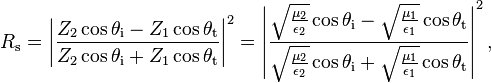

For non-magnetic media, we have μ1 = μ2 = μ0, so that


As a consequence of the conservation of energy, the transmittances are given by[2]


If the incident light is unpolarised (containing an equal mix of s- and p-polarisations), the reflectance is

The discussion given here assumes that the permeability μ is equal to the vacuum permeability μ0 in both media, embodying the assumption that the material is non-magnetic. This is approximately true for most dielectric materials, but not for some other types of material. The completely general Fresnel equations are more complicated.

For low-precision applications where polarization may be ignored, such as computer graphics, Schlick's approximation may be used.
Special angles
At one particular angle for a given n1 and n2, the value of Rp goes to zero and a p-polarised incident ray is purely refracted. This angle is known as Brewster's angle, and is around 56° for a glass medium in air or vacuum. Note that this statement is only true when the refractive indices of both materials are real numbers, as is the case for materials like air and glass. For materials that absorb light, like metals and semiconductors, n is complex, and Rp does not generally go to zero.When moving from a denser medium into a less dense one (i.e., n1 > n2), above an incidence angle known as the critical angle, all light is reflected and Rs = Rp =1. This phenomenon is known as total internal reflection. The critical angle is approximately 41° for glass in air.
Amplitude or field equations
Equations for coefficients corresponding to ratios of the electric field complex-valued amplitudes of the waves (not necessarily real-valued magnitudes) are also called "Fresnel equations". These take several different forms, depending on the choice of formalism and sign convention used. The amplitude coefficients are usually represented by lower case r and t.

Conventions used here
In this treatment, the coefficient r is the ratio of the reflected wave's complex electric field amplitude to that of the incident wave. The coefficient t is the ratio of the transmitted wave's electric field amplitude to that of the incident wave. The light is split into s and p polarizations as defined above. (In the figures to the right, s polarization is denoted " " and p is denoted "
 ".)
".)For s-polarization, a positive r or t means that the electric fields of the incoming and reflected or transmitted wave are parallel, while negative means anti-parallel. For p-polarization, a positive r or t means that the magnetic fields of the waves are parallel, while negative means anti-parallel.[3] It is also assumed that the magnetic permeability µ of both media is equal to the permeability of free space µ0.
(Be aware that some authors say instead use the opposite sign convention for rp, so that rp is positive when the incoming and reflected magnetic fields are antiparallel, and negative when they are parallel. This latter convention has the convenient advantage that the s- and p- sign conventions are the same at normal incidence. However, either convention, when used consistently, gives the right answers.)
Formulas
Using the arbitrary sign conventions above,[3]


Because the reflected and incident waves propagate in the same medium and make the same angle with the normal to the surface, the amplitude reflection coefficient is related to the reflectance R by [5]


Multiple surfaces
When light makes multiple reflections between two or more parallel surfaces, the multiple beams of light generally interfere with one another, resulting in net transmission and reflection amplitudes that depend on the light's wavelength. The interference, however, is seen only when the surfaces are at distances comparable to or smaller than the light's coherence length, which for ordinary white light is few micrometers; it can be much larger for light from a laser.An example of interference between reflections is the iridescent colours seen in a soap bubble or in thin oil films on water. Applications include Fabry–Pérot interferometers, antireflection coatings, and optical filters. A quantitative analysis of these effects is based on the Fresnel equations, but with additional calculations to account for interference.
The transfer-matrix method, or the recursive Rouard method[7] can be used to solve multiple-surface problems.


