From Wikipedia, the free encyclopedia

Space-based solar power (SBSP) is the concept of collecting solar power in space (using an "SPS", that is, a "solar-power satellite" or a "satellite power system") for use on Earth. It has been in research since the early 1970s.
SBSP would differ from current solar collection methods in that the means used to collect energy would reside on an orbiting satellite instead of on Earth's surface. Some projected benefits of such a system are a higher collection rate and a longer collection period due to the lack of a diffusing atmosphere and night time in space.
Part of the solar energy (55-60%) is lost on its way through the atmosphere by the effects of reflection and absorption. Space-based solar power systems convert sunlight to microwaves outside the atmosphere, avoiding these losses, and the downtime (and cosine losses, for fixed flat-plate collectors) due to the Earth's rotation.
Besides the cost of implementing such a system, SBSP also introduces several new hurdles, primarily the problem of transmitting energy from orbit to Earth's surface for use. Since wires extending from Earth's surface to an orbiting satellite are neither practical nor feasible with current technology, SBSP designs generally include the use of some manner of wireless power transmission. The collecting satellite would convert solar energy into electrical energy on board, powering a microwave transmitter or laser emitter, and focus its beam toward a collector (rectenna) on Earth's surface. Radiation and micrometeoroid damage could also become concerns for SBSP.
History

In 1941, science fiction writer Isaac Asimov published the science fiction short story "Reason", in which a space station transmits energy collected from the Sun to various planets using microwave beams.
The SBSP concept, originally known as satellite solar-power system (SSPS), was first described in November 1968.[1] In 1973 Peter Glaser was granted U.S. patent number 3,781,647 for his method of transmitting power over long distances (e.g. from an SPS to Earth's surface) using microwaves from a very large antenna (up to one square kilometer) on the satellite to a much larger one, now known as a rectenna, on the ground.[2]
Glaser then was a vice president at Arthur D. Little, Inc. NASA signed a contract with ADL to lead four other companies in a broader study in 1974. They found that, while the concept had several major problems – chiefly the expense of putting the required materials in orbit and the lack of experience on projects of this scale in space – it showed enough promise to merit further investigation and research.[3]
Between 1978 and 1986, the Congress authorized the Department of Energy (DoE) and NASA to jointly investigate the concept. They organized the Satellite Power System Concept Development and Evaluation Program.[4][5] The study remains the most extensive performed to date (budget $50 million).[6] Several reports were published investigating the engineering feasibility of such an engineering project. They include:

- Resource Requirements (Critical Materials, Energy, and Land)[7]
- Financial/Management Scenarios[8][9]
- Public Acceptance[10]
- State and Local Regulations as Applied to Satellite Power System Microwave Receiving Antenna Facilities[11]
- Student Participation[12]
- Potential of Laser for SBSP Power Transmission[13]
- International Agreements[14][15]
- Centralization/Decentralization[16]
- Mapping of Exclusion Areas For Rectenna Sites[17]
- Economic and Demographic Issues Related to Deployment[18]
- Some Questions and Answers[19]
- Meteorological Effects on Laser Beam Propagation and Direct Solar Pumped Lasers[20]
- Public Outreach Experiment[21]
- Power Transmission and Reception Technical Summary and Assessment[22]
- Space Transportation[23]
The Office of Technology Assessment[24] concluded
Too little is currently known about the technical, economic, and environmental aspects of SPS to make a sound decision whether to proceed with its development and deployment. In addition, without further research an SPS demonstration or systems-engineering verification program would be a high-risk venture.In 1997 NASA conducted its "Fresh Look" study to examine the modern state of SBSP feasibility.[25] In assessing "What has changed" since the DOE study, NASA asserted that:
US National Space Policy now calls for NASA to make significant investments in technology (not a particular vehicle) to drive the costs of ETO [Earth to Orbit] transportation down dramatically. This is, of course, an absolute requirement of space solar power.Conversely, Dr. Pete Worden claimed that space-based solar is about five orders of magnitude more expensive than solar power from the Arizona desert, with a major cost being the transportation of materials to orbit. Dr. Worden referred to possible solutions as speculative, and that would not be available for decades at the earliest.[26]
On Nov 2, 2012, China proposed space collaboration with India that mentioned SBSP, " . . . may be Space-based Solar Power initiative so that both India and China can work for long term association with proper funding along with other willing space faring nations to bring space solar power to earth."[27]
SERT

In 1999, NASA's Space Solar Power Exploratory Research and Technology program (SERT) was initiated for the following purposes:
- Perform design studies of selected flight demonstration concepts.
- Evaluate studies of the general feasibility, design, and requirements.
- Create conceptual designs of subsystems that make use of advanced SSP technologies to benefit future space or terrestrial applications.
- Formulate a preliminary plan of action for the U.S. (working with international partners) to undertake an aggressive technology initiative.
- Construct technology development and demonstration roadmaps for critical Space Solar Power (SSP) elements.
Some of SERT's conclusions:
- The increasing global energy demand is likely to continue for many decades resulting in new power plants of all sizes being built.
- The environmental impact of those plants and their impact on world energy supplies and geopolitical relationships can be problematic.
- Renewable energy is a compelling approach, both philosophically and in engineering terms.
- Many renewable energy sources are limited in their ability to affordably provide the base load power required for global industrial development and prosperity, because of inherent land and water requirements.
- Based on their Concept Definition Study, space solar power concepts may be ready to reenter the discussion.
- Solar power satellites should no longer be envisioned as requiring unimaginably large initial investments in fixed infrastructure before the emplacement of productive power plants can begin.
- Space solar power systems appear to possess many significant environmental advantages when compared to alternative approaches.
- The economic viability of space solar power systems depends on many factors and the successful development of various new technologies (not least of which is the availability of much lower cost access to space than has been available), however, the same can be said of many other advanced power technologies options.
- Space solar power may well emerge as a serious candidate among the options for meeting the energy demands of the 21st century. Space Solar Power Satellite Technology Development at the Glenn Research Center—An Overview] James E. Dudenhoefer and Patrick J. George, NASA Glenn Research Center, Cleveland, Ohio.
- Launch costs in the range of $100–$200 per kilogram of payload to low Earth orbit are needed if SPS are to be economically viable.[6]
JAXA
The May 2014 IEEE Spectrum magazine has a lengthy article "It's Always Sunny in Space" by Dr. Susumu Sasaki.[28] "It’s been the subject of many previous studies and the stuff of sci-fi for decades, but space-based solar power could at last become a reality—and within 25 years, according to a proposal from researchers at the Japan Aerospace Exploration Agency (JAXA)."Advantages
The SBSP concept is attractive because space has several major advantages over the Earth's surface for the collection of solar power.- There is no air in space, so the collecting surfaces could receive much more intense sunlight, unobstructed by the filtering effects of atmospheric gasses, cloud cover, there is no night, dust to be cleaned, clouds and other weather events. Consequently, the intensity in orbit is approximately 144% of the maximum attainable intensity on Earth's surface.[citation needed]
- A satellite could be illuminated over 99% of the time, and be in Earth's shadow a maximum of only 72 minutes per night at the spring and fall equinoxes at local midnight.[29] Orbiting satellites can be exposed to a consistently high degree of solar radiation, generally for 24 hours per day, whereas the average earth surface solar panels currently collect power for an average of 29% per day.[30]
- Power could be relatively quickly redirected directly to areas that need it most. A collecting satellite could possibly direct power on demand to different surface locations based on geographical baseload or peak load power needs. Typical contracts would be for baseload, continuous power, since peaking power is ephemeral.
- Elimination of plant and wildlife interference.
Disadvantages
The SBSP concept also has a number of problems.- The large cost of launching a satellite into space
- Inaccessibility: Maintenance of an earth-based solar panel is relatively simple, but construction and maintenance on a solar panel in space would typically be done telerobotically. In addition to cost, astronauts working in GEO orbit are exposed to unacceptably high radiation dangers and risk and cost about one thousand times more than the same task done telerobotically.
- After being decommissioned, parts of it may stay in orbit and become space debris. This space debris can create trouble for other space satellites.
- The space environment is hostile; panels suffer about 8 times the degradation they would on Earth.[31]
- Space debris is a major hazard to large objects in space, and all large structures such as SBSP systems have been mentioned as potential sources of orbital debris.[32]
- The broadcast frequency of the microwave downlink (if used) would require isolating the SBSP systems away from other satellites. GEO space is already well used and it is considered unlikely the ITU would allow an SPS to be launched.[33]
- The large size and corresponding cost of the receiving station on the ground.
Design

Space-based solar power essentially consists of three elements:
- a means of collecting solar power in space, for example via solar concentrators, solar cells or a heat engine
- a means of transmitting power to earth, for example via microwave or laser
- a means of receiving power on earth, for example via a microwave antenna (rectenna)
Two basic methods of conversion have been studied: photovoltaic (PV) and solar dynamic (SD). Photovoltaic conversion uses semiconductor cells to directly convert photons into electrical power. Solar dynamic uses mirrors to concentrate light on a boiler. The use of solar dynamic could reduce mass per watt. Most analyses of SBSP have focused on photovoltaic conversion (commonly known as “solar cells”).
Wireless power transmission was proposed early on as a means to transfer energy from collection to the Earth's surface, using either microwave or laser radiation at a variety of frequencies.
Microwave power transmission[edit]
William C. Brown demonstrated in 1964, during Walter Cronkite's CBS News program, a microwave-powered model helicopter that received all the power it needed for flight from a microwave beam. Between 1969 and 1975, Bill Brown was technical director of a JPL Raytheon program that beamed 30 kW of power over a distance of 1-mile (1.6 km) at 84% efficiency.[34]Microwave power transmission of tens of kilowatts has been well proven by existing tests at Goldstone in California (1975)[34][35][36] and Grand Bassin on Reunion Island (1997).[37]
More recently, microwave power transmission has been demonstrated, in conjunction with solar energy capture, between a mountain top in Maui and the island of Hawaii (92 miles away), by a team under John C. Mankins.[38][39] Technological challenges in terms of array layout, single radiation element design, and overall efficiency, as well as the associated theoretical limits are presently a subject of research, as it is demonstrated by the Special Session on "Analysis of Electromagnetic Wireless Systems for Solar Power Transmission" to be held in the 2010 IEEE Symposium on Antennas and Propagation.[40]
In 2013, a useful overview was published, covering technologies and issues associated with microwave power transmission from space to ground. It includes an introduction to SPS, current research and future prospects.[41]
Laser power beaming
Laser power beaming was envisioned by some at NASA as a stepping stone to further industrialization of space. In the 1980s, researchers at NASA worked on the potential use of lasers for space-to-space power beaming, focusing primarily on the development of a solar-powered laser. In 1989 it was suggested that power could also be usefully beamed by laser from Earth to space. In 1991 the SELENE project (SpacE Laser ENErgy) had begun, which included the study of laser power beaming for supplying power to a lunar base. The SELENE program was a two-year research effort, but the cost of taking the concept to operational status was too high, and the official project ended in 1993 before reaching a space-based demonstration.[42]In 1988 the use of an Earth-based laser to power an electric thruster for space propulsion was proposed by Grant Logan, with technical details worked out in 1989. He proposed using diamond solar cells operating at 600 degrees to convert ultraviolet laser light.
Orbital location
The main advantage of locating a space power station in geostationary orbit is that the antenna geometry stays constant, and so keeping the antennas lined up is simpler. Another advantage is that nearly continuous power transmission is immediately available as soon as the first space power station is placed in orbit; other space-based power stations have much longer start-up times before they are producing nearly continuous power.A collection of LEO (Low Earth Orbit) space power stations has been proposed as a precursor to GEO (Geostationary Orbit) space-based solar power.[43]
Earth-based receiver
The Earth-based rectenna would likely consist of many short dipole antennas connected via diodes. Microwave broadcasts from the satellite would be received in the dipoles with about 85% efficiency.[44] With a conventional microwave antenna, the reception efficiency is better, but its cost and complexity are also considerably greater. Rectennas would likely be several kilometers across.In space applications
A laser SBSP could also power a base or vehicles on the surface of the Moon or Mars, saving on mass costs to land the power source. A spacecraft or another satellite could also be powered by the same means. In a 2012 report presented to NASA on Space Solar Power, the author mentions another potential use for the technology behind Space Solar Power could be for Solar Electric Propulsion Systems that could be used for interplanetary human exploration missions.[45] [46][47]Dealing with launch costs
One problem for the SBSP concept is the cost of space launches and the amount of material that would need to be launched.Reusable launch systems are predicted to provide lower launch costs to low Earth orbit (LEO).[48][49] As of November 2013[update], one company, SpaceX, is two years along on a privately funded multi-year development program for a reusable rocket launching system with the stated intention to commercialize "fully and rapidly reusable" launch technology.[50][51][52] SpaceX has completed eight test flights of their low-altitude booster return prototype, Grasshopper,[53] and one test flight of a high-altitude/high-velocity booster return test vehicle, with a second booster return test flight planned for early 2014.[54][55]
Much of the material launched need not be delivered to its eventual orbit immediately, which raises the possibility that high efficiency (but slower) engines could move SPS material from LEO to GEO at an acceptable cost. Examples include ion thrusters or nuclear propulsion.
Power beaming from geostationary orbit by microwaves carries the difficulty that the required 'optical aperture' sizes are very large. For example, the 1978 NASA SPS study required a 1-km diameter transmitting antenna, and a 10 km diameter receiving rectenna, for a microwave beam at 2.45 GHz. These sizes can be somewhat decreased by using shorter wavelengths, although they have increased atmospheric absorption and even potential beam blockage by rain or water droplets. Because of the thinned array curse, it is not possible to make a narrower beam by combining the beams of several smaller satellites. The large size of the transmitting and receiving antennas means that the minimum practical power level for an SPS will necessarily be high; small SPS systems will be possible, but uneconomic.
To give an idea of the scale of the problem, assuming a solar panel mass of 20 kg per kilowatt (without considering the mass of the supporting structure, antenna, or any significant mass reduction of any focusing mirrors) a 4 GW power station would weigh about 80,000 metric tons, all of which would, in current circumstances, be launched from the Earth. Very lightweight designs could likely achieve 1 kg/kW,[56] meaning 4,000 metric tons for the solar panels for the same 4 GW capacity station. This would be the equivalent of between 40 and 150 heavy-lift launch vehicle (HLLV) launches to send the material to low earth orbit, where it would likely be converted into subassembly solar arrays, which then could use high-efficiency ion-engine style rockets to (slowly) reach GEO (Geostationary orbit). With an estimated serial launch cost for shuttle-based HLLVs of $500 million to $800 million, and launch costs for alternative HLLVs at $78 million, total launch costs would range between $11 billion (low cost HLLV, low weight panels) and $320 billion ('expensive' HLLV, heavier panels).[citation needed] To these costs must be added the environmental impact of heavy space launch emissions, if such costs are to be used in comparison to earth-based energy production. For comparison, the direct cost of a new coal[57] or nuclear power plant ranges from $3 billion to $6 billion per GW (not including the full cost to the environment from CO2 emissions or storage of spent nuclear fuel, respectively); another example is the Apollo missions to the Moon cost a grand total of $24 billion (1970s' dollars), taking inflation into account, would cost $140 billion today, more expensive than the construction of the International Space Station.
However in 2013 based on Recent innovations, Electric Space: Space-Based Solar Power Technologies & Applications [58] suggested a new way to reduce costs by replacing smaller satellites and in lower Orbits.
Building from space
From lunar materials launched in orbit
Gerard O'Neill, noting the problem of high launch costs in the early 1970s, proposed building the SPS's in orbit with materials from the Moon.[59] Launch costs from the Moon are potentially much lower than from Earth, due to the lower gravity. This 1970s proposal assumed the then-advertised future launch costing of NASA's space shuttle. This approach would require substantial up front capital investment to establish mass drivers on the Moon.[60]Nevertheless, on 30 April 1979, the Final Report ("Lunar Resources Utilization for Space Construction") by General Dynamics' Convair Division, under NASA contract NAS9-15560, concluded that use of lunar resources would be cheaper than Earth-based materials for a system of as few as thirty Solar Power Satellites of 10GW capacity each.[61]
In 1980, when it became obvious NASA's launch cost estimates for the space shuttle were grossly optimistic, O'Neill et al. published another route to manufacturing using lunar materials with much lower startup costs.[62] This 1980s SPS concept relied less on human presence in space and more on partially self-replicating systems on the lunar surface under remote control of workers stationed on Earth. The high net energy gain of this proposal derives from the Moon's much shallower gravitational well.
Having a relatively cheap per pound source of raw materials from space would lessen the concern for low mass designs and result in a different sort of SPS being built. The low cost per pound of lunar materials in O'Neill's vision would be supported by using lunar material to manufacture more facilities in orbit than just solar power satellites.
Advanced techniques for launching from the Moon may reduce the cost of building a solar power satellite from lunar materials. Some proposed techniques include the lunar mass driver and the lunar space elevator, first described by Jerome Pearson.[63] It would require establishing silicon mining and solar cell manufacturing facilities on the Moon.[citation needed]
On the Moon
David Criswell suggests the Moon is the optimum location for solar power stations, and promotes lunar solar power.[64][65] The main advantage he envisions is construction largely from locally available lunar materials, using in-situ resource utilization, with a teleoperated mobile factory and crane to assemble the microwave reflectors, and rovers to assemble and pave solar cells,[66] which would significantly reduce launch costs compared to SBSP designs. Power relay satellites orbiting around earth and the Moon reflecting the microwave beam are also part of the project. A demo project of 1 GW starts at $50 billion.[67] The Shimizu Corporation use combination of lasers and microwave for the lunar ring concept, along with power relay satellites.[68][69]From an asteroid
Asteroid mining has also been seriously considered. A NASA design study[70] evaluated a 10,000 ton mining vehicle (to be assembled in orbit) that would return a 500,000 ton asteroid fragment to geostationary orbit. Only about 3,000 tons of the mining ship would be traditional aerospace-grade payload. The rest would be reaction mass for the mass-driver engine, which could be arranged to be the spent rocket stages used to launch the payload. Assuming that 100% of the returned asteroid was useful, and that the asteroid miner itself couldn't be reused, that represents nearly a 95% reduction in launch costs. However, the true merits of such a method would depend on a thorough mineral survey of the candidate asteroids; thus far, we have only estimates of their composition.[71] One proposal is to capture the asteroid Apophis into earth orbit and convert it into 150 solar power satellites of 5 GW each or the larger asteroid 1999 AN10 which is 50x the size of Apophis and large enough to build 7,500 5-Gigawatt Solar Power Satellites[72]Gallery
-
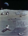
 A Lunar base with a mass driver (the long structure that goes toward the horizon). NASA conceptual illustration
 -
 An artist's conception of a "self-growing" robotic lunar factory.
 -
 Microwave reflectors on the moon and teleoperated robotic paving rover and crane.
 -
 “Crawler” traverses Lunar surface, smoothing, melting a top layer of regolith, then depositing elements of silicon PV cells directly on surface
 -
 Sketch of the Lunar Crawler to be used for fabrication of lunar solar cells on the surface of the Moon.
 -
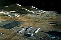
 Shown here is an array of solar collectors that convert power into microwave beams directed toward Earth.
 -
 A solar power satellite built from a mined asteroid.


Counter arguments
Safety
The use of microwave transmission of power has been the most controversial issue in considering any SPS design.At the Earth's surface, a suggested microwave beam would have a maximum intensity at its center, of 23 mW/cm2 (less than 1/4 the solar irradiation constant), and an intensity of less than 1 mW/cm2 outside the rectenna fenceline (the receiver's perimeter).[73] These compare with current United States Occupational Safety and Health Act (OSHA) workplace exposure limits for microwaves, which are 10 mW/cm2,[74] - the limit itself being expressed in voluntary terms and ruled unenforceable for Federal OSHA enforcement purposes.[citation needed] A beam of this intensity is therefore at its center, of a similar magnitude to current safe workplace levels, even for long term or indefinite exposure. Outside the receiver, it is far less than the OSHA long-term levels[75] Over 95% of the beam energy will fall on the rectenna. The remaining microwave energy will be absorbed and dispersed well within standards currently imposed upon microwave emissions around the world.[76] It is important for system efficiency that as much of the microwave radiation as possible be focused on the rectenna. Outside the rectenna, microwave intensities rapidly decrease, so nearby towns or other human activity should be completely unaffected.[77]
Exposure to the beam is able to be minimized in other ways. On the ground, physical access is controllable (e.g., via fencing), and typical aircraft flying through the beam provide passengers with a protective metal shell (i.e., a Faraday Cage), which will intercept the microwaves. Other aircraft (balloons, ultralight, etc.) can avoid exposure by observing airflight control spaces, as is currently done for military and other controlled airspace.
The microwave beam intensity at ground level in the center of the beam would be designed and physically built into the system; simply, the transmitter would be too far away and too small to be able to increase the intensity to unsafe levels, even in principle.
In addition, a design constraint is that the microwave beam must not be so intense as to injure wildlife, particularly birds. Experiments with deliberate microwave irradiation at reasonable levels have failed to show negative effects even over multiple generations.[78]
Some have suggested locating rectennas offshore,[79][80] but this presents serious problems, including corrosion, mechanical stresses, and biological contamination.
A commonly proposed approach to ensuring fail-safe beam targeting is to use a retrodirective phased array antenna/rectenna. A "pilot" microwave beam emitted from the center of the rectenna on the ground establishes a phase front at the transmitting antenna. There, circuits in each of the antenna's subarrays compare the pilot beam's phase front with an internal clock phase to control the phase of the outgoing signal. This forces the transmitted beam to be centered precisely on the rectenna and to have a high degree of phase uniformity; if the pilot beam is lost for any reason (if the transmitting antenna is turned away from the rectenna, for example) the phase control value fails and the microwave power beam is automatically defocused.[77] Such a system would be physically incapable of focusing its power beam anywhere that did not have a pilot beam transmitter.
The long-term effects of beaming power through the ionosphere in the form of microwaves has yet to be studied, but nothing has been suggested which might lead to any significant effect.
Timeline
- 1941: Isaac Asimov published the science fiction short story "Reason," in which a space station transmits energy collected from the sun to various planets using microwave beams.
- 1968: Dr. Peter Glaser introduces the concept of a "solar power satellite" system with square miles of solar collectors in high geosynchronous orbit for collection and conversion of sun's energy into a microwave beam to transmit usable energy to large receiving antennas (rectennas) on Earth for distribution.
- 1973: Dr. Peter Glaser is granted United States patent number 3,781,647 for his method of transmitting power over long distances using microwaves from a large (one square kilometer) antenna on the satellite to a much larger one on the ground, now known as a rectenna.[2]
- 1978–81: The United States Department of Energy and NASA examine the solar power satellite (SPS) concept extensively, publishing design and feasibility studies.
- 1982: Boeing proposal[81]
- 1987: Stationary High Altitude Relay Platform a Canadian experiment
- 1994: The United States Air Force conducts the Advanced Photovoltaic Experiment using a satellite launched into low Earth orbit by a Pegasus rocket.
- 1995–97: NASA conducts a “Fresh Look” study of space solar power (SSP) concepts and technologies.
- 1998: The Space Solar Power Concept Definition Study (CDS) identifies credible, commercially viable SSP concepts, while pointing out technical and programmatic risks.
- 1998: Japan's space agency begins developing a Space Solar Power System (SSPS), a program that continues to the present day.
- 1999: NASA's Space Solar Power Exploratory Research and Technology program (SERT, see below) begins.
- 2000: John Mankins of NASA testifies in the U.S. House of Representatives, saying "Large-scale SSP is a very complex integrated system of systems that requires numerous significant advances in current technology and capabilities. A technology roadmap has been developed that lays out potential paths for achieving all needed advances — albeit over several decades.[6]
- 2001: Dr. Neville Marzwell of NASA states, "We now have the technology to convert the sun's energy at the rate of 42 to 56 percent... We have made tremendous progress. ...If you can concentrate the sun's rays through the use of large mirrors or lenses you get more for your money because most of the cost is in the PV arrays... There is a risk element but you can reduce it... You can put these small receivers in the desert or in the mountains away from populated areas. ...We believe that in 15 to 25 years we can lower that cost to 7 to 10 cents per kilowatt hour. ...We offer an advantage. You don't need cables, pipes, gas or copper wires. We can send it to you like a cell phone call—where you want it and when you want it, in real time."[82]
- 2001: NASDA (One of Japan's national space agencies before it became part of JAXA) announces plans to perform additional research and prototyping by launching an experimental satellite with 10 kilowatts and 1 megawatt of power.[83][84]
- 2003: ESA studies[85]
- 2007: The US Pentagon's National Security Space Office (NSSO) issues a report[86] on October 10, 2007 stating they intend to collect solar energy from space for use on Earth to help the United States' ongoing relationship with the Middle East and the battle for oil. A demo plant could cost $ 10 billion, produce 10 megawatts, and become operational in 10 years.[87] The International Space Station may be the first test ground for this new idea, even though it is in a low-earth orbit.
- 2007: In May 2007 a workshop is held at the US Massachusetts Institute of Technology (MIT) to review the current state of the SBSP market and technology.[88]
- 2009: Several companies announce future SBSP partnerships and commitments, including Pacific Gas and Electric (PG&E) & Solaren,[89][90][91] Mitsubishi Electric Corp. & IHI Corporation,[92][93] Space Energy, Inc.,[94] and Japan Aerospace Exploration Agency.[95]
- 2010: Europe's EADS Astrium announces SBSP plans.[96][97][98][99]
- 2010: Professors Andrea Massa and Giorgio Franceschetti announce a special session on the "Analysis of Electromagnetic Wireless Systems for Solar Power Transmission" at the 2010 Institute of Electrical and Electronics Engineers International Symposium on Antennas and Propagation.[100]
- 2010: The Indian Space Research Organisation and US' National Space Society launched a joint forum to enhance partnership in harnessing solar energy through space-based solar collectors. Called the Kalam-NSS Initiative after the former Indian President Dr APJ Abdul Kalam, the forum will lay the groundwork for the space-based solar power program which could see other countries joining in as well.[101]
- 2010: The National Forensics League announces the resolution for the 2011–2012 debate season to be substantial space exploration and/or development. Space Based Solar Power becomes one of the most popular affirmative arguments.
- 2012: China proposed joint development between India and China towards developing a solar power satellite, during a visit by former Indian President Dr APJ Abdul Kalam.[102]
In fiction
Space stations transmitting solar power have appeared in science-fiction works like Isaac Asimov's Reason (1941), that centers around the troubles caused by the robots operating the station. Asimov's short story "The Last Question" also features the use of SBSP to provide limitless energy for use on Earth.In the video game Sid Meier's Alpha Centauri, the player can construct a city improvement called an "Orbital Power Transmitter" which, while expensive, provides energy to all other cities. Constructing many of these results in huge bonuses to energy production for all cities the player owns.
In the novel "Skyfall" (1976) by Harry Harrison an attempt to launch the core of powersat from Cape Canaveral ends in disaster when the launch vehicle fails trapping the payload in a decaying orbit.
Several Simcity games have featured space-microwave power plants as buildable options for municipal energy, along with (unrealistic) disaster scenarios where the beam strays off the collector and sets fire to nearby areas.
In the manga and anime Mobile Suit Gundam 00, an orbital ring containing multiple solar collectors and microwave transmitters, along with power stations and space elevators for carrying power back down to Earth's surface, are the primary source of electricity for the Earth in the 22nd century.


-_Highly_folded_Hetero-junction,_(b)-_Hetero-junction_with_controlled_growth.JPG)
_Vapor_thermal_Evaporation.JPG)


