Search This Blog

Saturday, August 5, 2023

Mars landing

From Wikipedia, the free encyclopedia
Animation of a Mars landing touchdown, the InSight lander in 2018

A Mars landing is a landing of a spacecraft on the surface of Mars. Of multiple attempted Mars landings by robotic, uncrewed spacecraft, ten have had successful soft landings. There have also been studies for a possible human mission to Mars, including a landing, but none have been attempted. Soviet Union’s Mars 3, which landed in 1971, was the first successful Mars landing. As of 2023, the Soviet Union, United States, and China have conducted Mars landings successfully.

Methods of descent and landing

As of 2021, all methods of landing on Mars have used an aeroshell and parachute sequence for Mars atmospheric entry and descent, but after the parachute is detached, there are three options. A stationary lander can drop from the parachute back shell and ride retrorockets all the way down, but a rover cannot be burdened with rockets that serve no purpose after touchdown.

One method for lighter rovers is to enclose the rover in a tetrahedral structure which in turn is enclosed in airbags. After the aeroshell drops off, the tetrahedron is lowered clear of the parachute back shell on a tether so that the airbags can inflate. Retrorockets on the back shell can slow descent. When it nears the ground, the tetrahedron is released to drop to the ground, using the airbags as shock absorbers. When it has come to rest, the tetrahedron opens to expose the rover.

If a rover is too heavy to use airbags, the retrorockets can be mounted on a sky crane. The sky crane drops from the parachute back shell and, as it nears the ground, the rover is lowered on a tether. When the rover touches ground, it cuts the tether so that the sky crane (with its rockets still firing) will crash well away from the rover.

Descent of heavier payloads

The thrusters of the InSight lander dug pits during landing beneath it at its landing site.

For landers that are even heavier than the Curiosity rover (which required a 4.5 meter (15 feet) diameter aeroshell), engineers are developing a combination rigid-inflatable Low-Density Supersonic Decelerator that could be 8 meters (28 feet) in diameter. It would have to be accompanied by a proportionately larger parachute.

Landing challenges

Landing robotic spacecraft, and possibly some day humans, on Mars is a technological challenge. For a favorable landing, the lander module has to address these issues:

In 2018, NASA successfully landed the InSight lander on the surface of Mars, re-using Viking-era technology. But this technology cannot afford the ability to land large number of cargoes, habitats, ascent vehicles and humans in case of crewed Mars missions in near future. In order to improve and accomplish this intent, there is need to upgrade technologies and launch vehicles. For a successive soft-landing using current technology, some of the considerable factors for a lander such as:

Communicating with Earth

Beginning with the Viking program, all landers on the surface of Mars have used orbiting spacecraft as communications satellites for relaying their data to Earth. The landers use UHF transmitters to send their data to the orbiters, which then relay the data to Earth using either X band or Ka band frequencies. These higher frequencies, along with more powerful transmitters and larger antennas, permit the orbiters to send the data much faster than the landers could manage transmitting directly to Earth, which conserves valuable time on the receiving antennas.

List of Mars landings

Insight Mars lander view in December 2018

In the 1970s, several USSR probes unsuccessfully tried to land on Mars. Mars 3 landed successfully in 1971 but failed shortly thereafter. The American Viking landers however made it to the surface and provided several years of images and data. However, there was not another successful Mars landing until 1997, when Mars Pathfinder landed. In the 21st century there have been several successful landings, but there have also been many crashes.

Mars probe program

The first probe intended to be a Mars impact lander was the Soviet Mars 1962B, unsuccessfully launched in 1962.

In 1970 the Soviet Union began the design of Mars 4NM and Mars 5NM missions with super-heavy uncrewed Martian spacecraft. First was Marsokhod, with a planned date of early 1973, and second was the Mars sample return mission planned for 1975. Both spacecraft were intended to be launched on the N1 rocket, but this rocket never flew successfully and the Mars 4NM and Mars 5NM projects were cancelled.

In 1971 the Soviet Union sent probes Mars 2 and Mars 3, each carrying a lander, as part of the Mars probe program M-71. The Mars 2 lander failed to land and impacted Mars. The Mars 3 lander became the first probe to successfully soft-land on Mars, but its data-gathering had less success. The lander began transmitting to the Mars 3 orbiter 90 seconds after landing, but after 14.5 seconds, transmission ceased for unknown reasons. The cause of the failure may have been related to the extremely powerful Martian dust storm taking place at the time. These space probes each contained a Mars rover although they were never deployed.

In 1973, the Soviet Union sent two more landers to Mars, Mars 6 and Mars 7. The Mars 6 lander transmitted data during descent but failed upon impact. The Mars 7 probe separated prematurely from the carrying vehicle due to a problem in the operation of one of the onboard systems (attitude control or retro-rockets) and missed the planet by 1,300 km (810 mi).

The double-launching Mars 5M (Mars-79) sample return mission was planned for 1979, but was cancelled due to complexity and technical problems.

Viking program
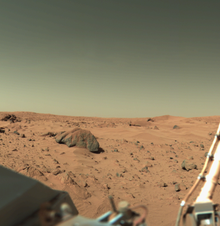
Viking 1 landing site (click image for detailed description).

In 1976 two American Viking probes entered orbit about Mars and each released a lander module that made a successful soft landing on the planet's surface. They subsequently had the first successful transmission of large volumes of data, including the first color pictures and extensive scientific information. Measured temperatures at the landing sites ranged from 150 to 250 K (−123 to −23 °C; −190 to −10 °F), with a variation over a given day of 35 to 50 °C (95 to 122 °F). Seasonal dust storms, pressure changes, and movement of atmospheric gases between the polar caps were observed. A biology experiment produced possible evidence of life, but it was not corroborated by other on-board experiments.

While searching for a suitable landing spot for Viking 2's lander, the Viking 1 orbiter photographed the landform that constitutes the so-called "Face on Mars" on 25 July 1976.

The Viking program was a descendant of the cancelled Voyager program, whose name was later reused for a pair of outer solar system probes.

Mars Pathfinder

"Ares Vallis" as photographed by Mars Pathfinder

NASA's Mars Pathfinder spacecraft, with assistance from the Mars Global Surveyor orbiter, landed on 4 July 1997. Its landing site was an ancient flood plain in Mars' northern hemisphere called Ares Vallis, which is among the rockiest parts of Mars. It carried a tiny remote-controlled rover called Sojourner, the first successful Mars rover, that traveled a few meters around the landing site, exploring the conditions and sampling rocks around it. Newspapers around the world carried images of the lander dispatching the rover to explore the surface of Mars in a way never achieved before.

Until the final data transmission on 27 September 1997, Mars Pathfinder returned 16,500 images from the lander and 550 images from the rover, as well as more than 15 chemical analyses of rocks and soil and extensive data on winds and other weather factors. Findings from the investigations carried out by scientific instruments on both the lander and the rover suggest that in the past Mars has been warm and wet, with liquid water and a thicker atmosphere. The mission website was the most heavily trafficked up to that time.

Spate of failures

Conceptual drawing of the Mars Polar Lander on the surface of Mars.
Mars Spacecraft 1988–1999
Spacecraft Evaluation Had or was Lander
Phobos 1 No For Phobos
Phobos 2 Yes For Phobos
Mars Observer No No
Mars 96 No Yes
Mars Pathfinder Yes Yes
Mars Global Surveyor Yes No
Mars Climate Orbiter No No
Mars Polar Lander No Yes
Deep Space 2 No Yes
Nozomi No No

Mars 96, an orbiter launched on 16 November 1996 by Russia, failed when the planned second burn of the Block D-2 fourth stage did not occur. Following the success of Global Surveyor and Pathfinder, another spate of failures occurred in 1998 and 1999, with the Japanese Nozomi orbiter and NASA's Mars Climate Orbiter, Mars Polar Lander, and Deep Space 2 penetrators all suffering various terminal errors. Mars Climate Orbiter is infamous for Lockheed Martin engineers mixing up the usage of U.S. customary units with metric units, causing the orbiter to burn up while entering Mars's atmosphere. Out of 5–6 NASA missions in the 1990s, only 2 worked: Mars Pathfinder and Mars Global Surveyor, making Mars Pathfinder and its rover the only successful Mars landing in the 1990s.

Mars Express and Beagle 2

On 2 June 2003, the European Space Agency's Mars Express set off from Baikonur Cosmodrome to Mars. The Mars Express craft consisted of the Mars Express Orbiter and the lander Beagle 2. Although the landing probe was not designed to move, it carried a digging device and the least massive spectrometer created to date, as well as a range of other devices, on a robotic arm in order to accurately analyse soil beneath the dusty surface.

The orbiter entered Mars orbit on 25 December 2003, and Beagle 2 should have entered Mars' atmosphere the same day. However, attempts to contact the lander failed. Communications attempts continued throughout January, but Beagle 2 was declared lost in mid-February, and a joint inquiry was launched by the UK and ESA that blamed principal investigator Colin Pillinger's poor project management. Nevertheless, Mars Express Orbiter confirmed the presence of water ice and carbon dioxide ice at the planet's south pole. NASA had previously confirmed their presence at the north pole of Mars.

Signs of the Beagle 2 lander were found in 2013 by the HiRISE camera on NASA's Mars Reconnaissance Orbiter, and the Beagle 2's presence was confirmed in January 2015, several months after Pillinger's death. The lander appears to have successfully landed but not deployed all of its power and communications panels.

Mars Exploration Rovers

Shortly after the launch of Mars Express, NASA sent a pair of twin rovers toward the planet as part of the Mars Exploration Rover mission. On 10 June 2003, NASA's MER-A (Spirit) Mars Exploration Rover was launched. It successfully landed in Gusev Crater (believed once to have been a crater lake) on 3 January 2004. It examined rock and soil for evidence of the area's history of water. On 7 July 2003, a second rover, MER-B (Opportunity) was launched. It landed on 24 January 2004 in Meridiani Planum (where there are large deposits of hematite, indicating the presence of past water) to carry out similar geological work.

Despite a temporary loss of communication with the Spirit rover (caused by a file system anomaly) delaying exploration for several days, both rovers eventually began exploring their landing sites. The rover Opportunity landed in a particularly interesting spot, a crater with bedrock outcroppings. In fast succession, mission team members announced on 2 March that data returned from the rover showed that these rocks were once "drenched in water", and on 23 March that it was concluded that they were laid down underwater in a salty sea. This represented the first strong direct evidence for liquid water on Mars at some time in the past.

Towards the end of July 2005, it was reported by the Sunday Times that the rovers may have carried the bacteria Bacillus safensis to Mars. According to one NASA microbiologist, this bacteria could survive both the trip and conditions on Mars. Despite efforts to sterilise both landers, neither could be assured to be completely sterile.

Having been designed for only three-month missions, both rovers lasted much longer than planned. Spirit lost contact with Earth in March 2010, 74 months after commencing exploration. Opportunity, however, continued to carry out surveys of the planet, surpassing 45 km (28 mi) on its odometer by the time communication with it was lost in June 2018, 173 months after it began. These rovers have discovered many new things, including Heat Shield Rock, the first meteorite to be discovered on another planet.

Here is some debris from a Mars landing, as viewed by a Rover. This shows the area around a heat shield and resulting shield impact crater. The heat shield was jettisoned during the descent, impacting the surface on its own trajectory, while the spacecraft went on to land the rover.

Phoenix

Camera on Mars orbiter snaps Phoenix suspended from its parachute during descent through Mars' atmosphere.

Phoenix launched on 4 August 2007, and touched down on the northern polar region of Mars on 25 May 2008. It is famous for having been successfully photographed while landing, since this was the first time one spacecraft captured the landing of another spacecraft onto a planet.

Mars Science Laboratory

Mars Science Laboratory (and the Curiosity rover) descending on Mars

The Mars Science Laboratory (MSL) (and Curiosity rover), launched in November 2011, landed in a location that is now called "Bradbury Landing", on Aeolis Palus, between Peace Vallis and Aeolis Mons ("Mount Sharp"), in Gale Crater on Mars on 6 August 2012, 05:17 UTC. The landing site was in Quad 51 ("Yellowknife") of Aeolis Palus near the base of Aeolis Mons. The landing site was less than 2.4 km (1.5 mi) from the center of the rover's planned target site after a 563,000,000 km (350,000,000 mi) journey. NASA named the landing site "Bradbury Landing", in honor of author Ray Bradbury, on 22 August 2012.

ExoMars Schiaparelli

Model of Schiaparelli lander at ESOC

The Schiaparelli lander was intended to test technology for future soft landings on the surface of Mars as part of the ExoMars project. It was built in Italy by the European Space Agency (ESA) and Roscosmos. It was launched together with the ExoMars Trace Gas Orbiter (TGO) on 14 March 2016 and attempted a landing on 19 October 2016. Telemetry was lost about one minute before the scheduled landing time, but confirmed that most elements of the landing plan, including heat shield operation, parachute deployment, and rocket activation, had been successful. The Mars Reconnaissance Orbiter later captured imagery showing what appears to be Schiaparelli's crash site.

InSight
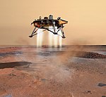
Phoenix landing art, similar to Insight

NASA's InSight lander, designed to study seismology and heat flow from the deep interior of Mars, was launched on 5 May 2018. It landed successfully in Mars's Elysium Planitia on 26 November 2018.

Mars 2020 and Tianwen-1

NASA's Mars 2020 and CNSA's Tianwen-1 were both launched in the July 2020 window. Mars 2020's rover Perseverance successfully landed, in a location that is now called "Octavia E. Butler Landing", in Jezero Crater on 18 February 2021, Ingenuity helicopter was deployed and took subsequent flights in April. Tianwen-1's lander and Zhurong rover landed in Utopia Planitia on 14 May 2021 with the rover being deployed on 22 May, 2021 and dropping a remote selfie camera on 1 June, 2021.

Future missions

The ESA Rosalind Franklin is planned for launch in the late 2020s and would obtain soil samples from up to 2 metres (6 ft 7 in) depth and make an extensive search for biosignatures and biomolecules. There is also a proposal for a Mars Sample Return Mission by ESA and NASA, which would launch in 2024 or later. This mission would be part of the European Aurora Programme.

The Indian Space Research Organisation (ISRO) has proposed to include landing of a rover in its third Mars mission around 2030 near Eridania basin.

Landing site identification

As a Mars lander approaches the surface, identifying a safe landing spot is a concern.

The inset frames show how the lander's descent imaging system is identifying hazards (NASA, 1990)
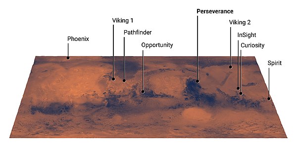
Mars Landing Sites (16 December 2020]
Map of Mars
Interactive image map of the global topography of Mars, overlaid with the position of Martian rovers and landers. Coloring of the base map indicates relative elevations of Martian surface.
Clickable image: Clicking on the labels will open a new article.
Legend:   Active (white lined, ※)  Inactive  Planned (dash lined, ⁂)
Bradbury Landing
Deep Space 2
Mars Polar Lander
Perseverance
Schiaparelli EDM
Spirit
Viking 1
Map of MarsAcheron FossaeAcidalia PlanitiaAlba MonsAmazonis PlanitiaAonia PlanitiaArabia TerraArcadia PlanitiaArgentea PlanumArgyre PlanitiaChryse PlanitiaClaritas FossaeCydonia MensaeDaedalia PlanumElysium MonsElysium PlanitiaGale craterHadriaca PateraHellas MontesHellas PlanitiaHesperia PlanumHolden craterIcaria PlanumIsidis PlanitiaJezero craterLomonosov craterLucus PlanumLycus SulciLyot craterLunae PlanumMalea PlanumMaraldi craterMareotis FossaeMareotis TempeMargaritifer TerraMie craterMilankovič craterNepenthes MensaeNereidum MontesNilosyrtis MensaeNoachis TerraOlympica FossaeOlympus MonsPlanum AustralePromethei TerraProtonilus MensaeSirenumSisyphi PlanumSolis PlanumSyria PlanumTantalus FossaeTempe TerraTerra CimmeriaTerra SabaeaTerra SirenumTharsis MontesTractus CatenaTyrrhen TerraUlysses PateraUranius PateraUtopia PlanitiaValles MarinerisVastitas BorealisXanthe Terra
The image above contains clickable links

Interactive image map of the global topography of Mars, overlain with locations of Mars Memorial sites. Hover your mouse over the image to see the names of over 60 prominent geographic features, and click to link to them. Coloring of the base map indicates relative elevations, based on data from the Mars Orbiter Laser Altimeter on NASA's Mars Global Surveyor. Whites and browns indicate the highest elevations (+12 to +8 km); followed by pinks and reds (+8 to +3 km); yellow is 0 km; greens and blues are lower elevations (down to −8 km). Axes are latitude and longitude; Polar regions are noted.

Radio wave

From Wikipedia, the free encyclopedia
 
Animation of a half-wave dipole antenna radiating radio waves, showing the electric field lines. The antenna in the center is two vertical metal rods connected to a radio transmitter (not shown). The transmitter applies an alternating electric current to the rods, which charges them alternately positive (+) and negative (−). Loops of electric field leave the antenna and travel away at the speed of light; these are the radio waves. In this animation the action is shown slowed down tremendously.

Radio waves are a type of electromagnetic radiation with the longest wavelengths in the electromagnetic spectrum, typically with frequencies of 300 gigahertz (GHz) and below.[citation needed] At 300 GHz, the corresponding wavelength is 1mm, which is shorter than the diameter of a grain of rice. At 30 Hz the corresponding wavelength is ~10,000 kilometers (6,200 miles) longer than the radius of the Earth. Wavelength of a radio wave is inversely proportional to its frequency, because its velocity is constant. Like all electromagnetic waves, radio waves in a vacuum travel at the speed of light, and in the Earth's atmosphere at a slightly slower speed. Radio waves are generated by charged particles undergoing acceleration, such as time-varying electric currents. Naturally occurring radio waves are emitted by lightning and astronomical objects, and are part of the blackbody radiation emitted by all warm objects.

Radio waves are generated artificially by an electronic device called a transmitter, which is connected to an antenna which radiates the waves. They are received by another antenna connected to a radio receiver, which processes the received signal. Radio waves are very widely used in modern technology for fixed and mobile radio communication, broadcasting, radar and radio navigation systems, communications satellites, wireless computer networks and many other applications. Different frequencies of radio waves have different propagation characteristics in the Earth's atmosphere; long waves can diffract around obstacles like mountains and follow the contour of the earth (ground waves), shorter waves can reflect off the ionosphere and return to earth beyond the horizon (skywaves), while much shorter wavelengths bend or diffract very little and travel on a line of sight, so their propagation distances are limited to the visual horizon.

To prevent interference between different users, the artificial generation and use of radio waves is strictly regulated by law, coordinated by an international body called the International Telecommunication Union (ITU), which defines radio waves as "electromagnetic waves of frequencies arbitrarily lower than 3,000 GHz, propagated in space without artificial guide". The radio spectrum is divided into a number of radio bands on the basis of frequency, allocated to different uses.

Diagram of the electric fields (E) and magnetic fields (H) of radio waves emitted by a monopole radio transmitting antenna (small dark vertical line in the center). The E and H fields are perpendicular, as implied by the phase diagram in the lower right.

Discovery and exploitation

Radio waves were first predicted by the theory of electromagnetism proposed in 1867 by Scottish mathematical physicist James Clerk Maxwell. His mathematical theory, now called Maxwell's equations, predicted that a coupled electric and magnetic field could travel through space as an "electromagnetic wave". Maxwell proposed that light consisted of electromagnetic waves of very short wavelength. In 1887, German physicist Heinrich Hertz demonstrated the reality of Maxwell's electromagnetic waves by experimentally generating radio waves in his laboratory, showing that they exhibited the same wave properties as light: standing waves, refraction, diffraction, and polarization. Italian inventor Guglielmo Marconi developed the first practical radio transmitters and receivers around 1894–1895. He received the 1909 Nobel Prize in physics for his radio work. Radio communication began to be used commercially around 1900. The modern term "radio wave" replaced the original name "Hertzian wave" around 1912.

Generation and reception

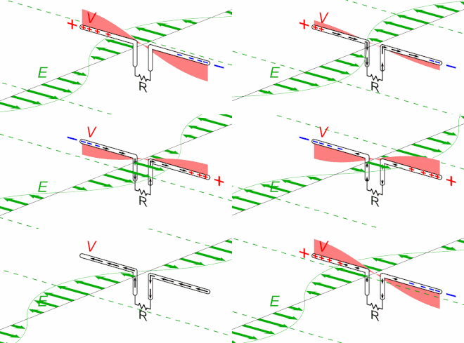
Animated diagram of a half-wave dipole antenna receiving a radio wave. The antenna consists of two metal rods connected to a receiver R. The electric field (E, green arrows) of the incoming wave pushes the electrons in the rods back and forth, charging the ends alternately positive (+) and negative (−). Since the length of the antenna is one half the wavelength of the wave, the oscillating field induces standing waves of voltage (V, represented by red band) and current in the rods. The oscillating currents (black arrows) flow down the transmission line and through the receiver (represented by the resistance R).

Radio waves are radiated by charged particles when they are accelerated. Natural sources of radio waves include radio noise produced by lightning and other natural processes in the Earth's atmosphere, and astronomical radio sources in space such as the Sun, galaxies and nebulas. All warm [DJS -- objects with temperatures above 0K?] objects radiate high frequency radio waves (microwaves) as part of their black body radiation.

Radio waves are produced artificially by time-varying electric currents, consisting of electrons flowing back and forth in a specially-shaped metal conductor called an antenna. An electronic device called a radio transmitter applies oscillating electric current to the antenna, and the antenna radiates the power as radio waves. Radio waves are received by another antenna attached to a radio receiver. When radio waves strike the receiving antenna they push the electrons in the metal back and forth, creating tiny oscillating currents which are detected by the receiver.

From quantum mechanics, like other electromagnetic radiation such as light, radio waves can alternatively be regarded as streams of uncharged elementary particles called photons. In an antenna transmitting radio waves, the electrons in the antenna emit the energy in discrete packets called radio photons, while in a receiving antenna the electrons absorb the energy as radio photons. An antenna is a coherent emitter of photons, like a laser, so the radio photons are all in phase. However, from Planck's relation the energy of individual radio photons is extremely small, from 10−22 to 10−30 joules. So the antenna of even a very low power transmitter emits enormous numbers of photons per second. Therefore, except for certain molecular electron transition processes such as atoms in a maser emitting microwave photons, radio wave emission and absorption is usually regarded as a continuous classical process, governed by Maxwell's equations.

Properties

Radio waves in a vacuum travel at the speed of light . When passing through a material medium, they are slowed depending on the medium's permeability and permittivity. Air is thin enough that in the Earth's atmosphere radio waves travel very close to the speed of light.

The wavelength is the distance from one peak (crest) of the wave's electric field to the next, and is inversely proportional to the frequency of the wave. The relation of frequency and wavelength in a radio wave traveling in vacuum or air is

where

Equivalently, the distance a radio wave travels in a vacuum, in one second, is 299,792,458 meters (983,571,056 ft), which is the wavelength of a 1 hertz radio signal. A 1 megahertz radio wave (mid-AM band) has a wavelength of 299.79 meters (983.6 ft).

Polarization

Like other electromagnetic waves, a radio wave has a property called polarization, which is defined as the direction of the wave's oscillating electric field perpendicular to the direction of motion. A plane polarized radio wave has an electric field which oscillates in a plane along the direction of motion. In a horizontally polarized radio wave the electric field oscillates in a horizontal direction. In a vertically polarized wave the electric field oscillates in a vertical direction. In a circularly polarized wave the electric field at any point rotates about the direction of travel, once per cycle. A right circularly polarized wave rotates in a right hand sense about the direction of travel, while a left circularly polarized wave rotates in the opposite sense. The wave's magnetic field is perpendicular to the electric field, and the electric and magnetic field are oriented in a right hand sense with respect to the direction of radiation.

An antenna emits polarized radio waves, with the polarization determined by the direction of the metal antenna elements. For example a dipole antenna consists of two collinear metal rods. If the rods are horizontal it radiates horizontally polarized radio waves, while if the rods are vertical it radiates vertically polarized waves. An antenna receiving the radio waves must have the same polarization as the transmitting antenna, or it will suffer a severe loss of reception. Many natural sources of radio waves, such as the sun, stars and blackbody radiation from warm objects, emit unpolarized waves, consisting of incoherent short wave trains in an equal mixture of polarization states.

The polarization of radio waves is determined by a quantum mechanical property of the photons called their spin. A photon can have one of two possible values of spin; it can spin in a right hand sense about its direction of motion, or in a left hand sense. Right circularly polarized radio waves consist of photons spinning in a right hand sense. Left circularly polarized radio waves consist of photons spinning in a left hand sense. Plane polarized radio waves consist of photons in a quantum superposition of right and left hand spin states. The electric field consists of a superposition of right and left rotating fields, resulting in a plane oscillation.

Propagation characteristics

Radio waves are more widely used for communication than other electromagnetic waves mainly because of their desirable propagation properties, stemming from their large wavelength. Radio waves have the ability to pass through the atmosphere in any weather, foliage, and most building materials, and by diffraction longer wavelengths can bend around obstructions, and unlike other electromagnetic waves they tend to be scattered rather than absorbed by objects larger than their wavelength.

The study of radio propagation, how radio waves move in free space and over the surface of the Earth, is vitally important in the design of practical radio systems. Radio waves passing through different environments experience reflection, refraction, polarization, diffraction, and absorption. Different frequencies experience different combinations of these phenomena in the Earth's atmosphere, making certain radio bands more useful for specific purposes than others. Practical radio systems mainly use three different techniques of radio propagation to communicate:

  • Line of sight: This refers to radio waves that travel in a straight line from the transmitting antenna to the receiving antenna. It does not necessarily require a cleared sight path; at lower frequencies radio waves can pass through buildings, foliage and other obstructions. This is the only method of propagation possible at frequencies above 30 MHz. On the surface of the Earth, line of sight propagation is limited by the visual horizon to about 64 km (40 mi). This is the method used by cell phones, FM, television broadcasting and radar. By using dish antennas to transmit beams of microwaves, point-to-point microwave relay links transmit telephone and television signals over long distances up to the visual horizon. Ground stations can communicate with satellites and spacecraft billions of miles from Earth.
    • Indirect propagation: Radio waves can reach points beyond the line-of-sight by diffraction and reflection. Diffraction causes radio waves to bend around obstructions such as a building edge, a vehicle, or a turn in a hall. Radio waves also partially reflect from surfaces such as walls, floors, ceilings, vehicles and the ground. These propagation methods occur in short range radio communication systems such as cell phones, cordless phones, walkie-talkies, and wireless networks. A drawback of this mode is multipath propagation, in which radio waves travel from the transmitting to the receiving antenna via multiple paths. The waves interfere, often causing fading and other reception problems.
  • Ground waves: At lower frequencies below 2 MHz, in the medium wave and longwave bands, due to diffraction vertically polarized radio waves can bend over hills and mountains, and propagate beyond the horizon, traveling as surface waves which follow the contour of the Earth. This makes it possible for mediumwave and longwave broadcasting stations to have coverage areas beyond the horizon, out to hundreds of miles. As the frequency drops, the losses decrease and the achievable range increases. Military very low frequency (VLF) and extremely low frequency (ELF) communication systems can communicate over most of the Earth. VLF and ELF radio waves can also penetrate water to hundreds of meters depth, so they are used to communicate with submerged submarines.
  • Skywaves: At medium wave and shortwave wavelengths, radio waves reflect off conductive layers of charged particles (ions) in a part of the atmosphere called the ionosphere. So radio waves directed at an angle into the sky can return to Earth beyond the horizon; this is called "skip" or "skywave" propagation. By using multiple skips communication at intercontinental distances can be achieved. Skywave propagation is variable and dependent on atmospheric conditions; it is most reliable at night and in the winter. Widely used during the first half of the 20th century, due to its unreliability skywave communication has mostly been abandoned. Remaining uses are by military over-the-horizon (OTH) radar systems, by some automated systems, by radio amateurs, and by shortwave broadcasting stations to broadcast to other countries.

At microwave frequencies, atmospheric gases begin absorbing radio waves, so the range of practical radio communication systems decreases with increasing frequency. Below about 20 GHz atmospheric attenuation is mainly due to water vapor. Above 20 GHz, in the millimeter wave band, other atmospheric gases begin to absorb the waves, limiting practical transmission distances to a kilometer or less. Above 300 GHz, in the terahertz band, virtually all the power is absorbed within a few meters, so the atmosphere is effectively opaque.

Radio communication

In radio communication systems, information is transported across space using radio waves. At the sending end, the information to be sent, in the form of a time-varying electrical signal, is applied to a radio transmitter. The information, called the modulation signal, can be an audio signal representing sound from a microphone, a video signal representing moving images from a video camera, or a digital signal representing data from a computer. In the transmitter, an electronic oscillator generates an alternating current oscillating at a radio frequency, called the carrier wave because it creates the radio waves that "carry" the information through the air. The information signal is used to modulate the carrier, altering some aspect of it, "piggybacking" the information on the carrier. The modulated carrier is amplified and applied to an antenna. The oscillating current pushes the electrons in the antenna back and forth, creating oscillating electric and magnetic fields, which radiate the energy away from the antenna as radio waves. The radio waves carry the information to the receiver location.

At the receiver, the oscillating electric and magnetic fields of the incoming radio wave push the electrons in the receiving antenna back and forth, creating a tiny oscillating voltage which is a weaker replica of the current in the transmitting antenna. This voltage is applied to the radio receiver, which extracts the information signal. The receiver first uses a bandpass filter to separate the desired radio station's radio signal from all the other radio signals picked up by the antenna, then amplifies the signal so it is stronger, then finally extracts the information-bearing modulation signal in a demodulator. The recovered signal is sent to a loudspeaker or earphone to produce sound, or a television display screen to produce a visible image, or other devices. A digital data signal is applied to a computer or microprocessor, which interacts with a human user.

The radio waves from many transmitters pass through the air simultaneously without interfering with each other. They can be separated in the receiver because each transmitter's radio waves oscillate at a different rate, in other words each transmitter has a different frequency, measured in kilohertz (kHz), megahertz (MHz) or gigahertz (GHz). The bandpass filter in the receiver consists of a tuned circuit which acts like a resonator, similarly to a tuning fork. It has a natural resonant frequency at which it oscillates. The resonant frequency is set equal to the frequency of the desired radio station. The oscillating radio signal from the desired station causes the tuned circuit to oscillate in sympathy, and it passes the signal on to the rest of the receiver. Radio signals at other frequencies are blocked by the tuned circuit and not passed on.

Biological and environmental effects

Radio waves are non-ionizing radiation, which means they do not have enough energy to separate electrons from atoms or molecules, ionizing them, or break chemical bonds, causing chemical reactions or DNA damage. The main effect of absorption of radio waves by materials is to heat them, similarly to the infrared waves radiated by sources of heat such as a space heater or wood fire. The oscillating electric field of the wave causes polar molecules to vibrate back and forth, increasing the temperature; this is how a microwave oven cooks food. However, unlike infrared waves, which are mainly absorbed at the surface of objects and cause surface heating, radio waves are able to penetrate the surface and deposit their energy inside materials and biological tissues. The depth to which radio waves penetrate decreases with their frequency, and also depends on the material's resistivity and permittivity; it is given by a parameter called the skin depth of the material, which is the depth within which 63% of the energy is deposited. For example, the 2.45 GHz radio waves (microwaves) in a microwave oven penetrate most foods approximately 2.5 to 3.8 cm (1 to 1.5 inches). Radio waves have been applied to the body for 100 years in the medical therapy of diathermy for deep heating of body tissue, to promote increased blood flow and healing. More recently they have been used to create higher temperatures in hyperthermia treatment and to kill cancer cells. Looking into a source of radio waves at close range, such as the waveguide of a working radio transmitter, can cause damage to the lens of the eye by heating. A strong enough beam of radio waves can penetrate the eye and heat the lens enough to cause cataracts.

Since the heating effect is in principle no different from other sources of heat, most research into possible health hazards of exposure to radio waves has focused on "nonthermal" effects; whether radio waves have any effect on tissues besides that caused by heating. Radiofrequency electromagnetic fields have been classified by the International Agency for Research on Cancer (IARC) as having "limited evidence" for its effects on humans and animals. There is weak mechanistic evidence of cancer risk via personal exposure to RF-EMF from mobile telephones.

Radio waves can be shielded against by a conductive metal sheet or screen, an enclosure of sheet or screen is called a Faraday cage. A metal screen shields against radio waves as well as a solid sheet as long as the holes in the screen are smaller than about 120 of wavelength of the waves.

Measurement

Since radio frequency radiation has both an electric and a magnetic component, it is often convenient to express intensity of radiation field in terms of units specific to each component. The unit volts per meter (V/m) is used for the electric component, and the unit amperes per meter (A/m) is used for the magnetic component. One can speak of an electromagnetic field, and these units are used to provide information about the levels of electric and magnetic field strength at a measurement location.

Another commonly used unit for characterizing an RF electromagnetic field is power density. Power density is most accurately used when the point of measurement is far enough away from the RF emitter to be located in what is referred to as the far field zone of the radiation pattern. In closer proximity to the transmitter, i.e., in the "near field" zone, the physical relationships between the electric and magnetic components of the field can be complex, and it is best to use the field strength units discussed above. Power density is measured in terms of power per unit area, for example, milliwatts per square centimeter (mW/cm2). When speaking of frequencies in the microwave range and higher, power density is usually used to express intensity since exposures that might occur would likely be in the far field zone.

Delayed-choice quantum eraser

From Wikipedia, the free encyclopedia https://en.wikipedia.org/wiki/Delayed-choice_quantum_eraser A delayed-cho...