The New York City Subway is the world's largest single operator rapid transit system by number of stations served, utilizing hundreds of miles of electrified track.
The Shanghai Metro is the world's largest single operator rapid transit system by length, possessing hundreds of kilometers of electrified lines.
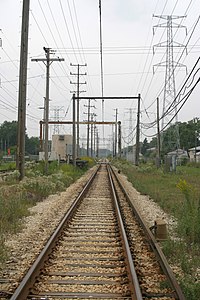
Transition zone of third-rail to overhead-wire supply on Chicago's Yellow Line (the "Skokie Swift")
A railway electrification system supplies electric power to railway trains and trams without an on-board prime mover or local fuel supply.
Electric railways use either electric locomotives (hauling passengers or freight in separate cars) or electric multiple units (passenger cars with their own motors).
Electricity is typically generated in large and relatively efficient generating stations,
transmitted to the railway network and distributed to the trains. Some
electric railways have their own dedicated generating stations and transmission lines, but most purchase power from an electric utility. The railway usually provides its own distribution lines, switches, and transformers.
Power is supplied to moving trains with a (nearly) continuous conductor running along the track that usually takes one of two forms: an overhead line, suspended from poles or towers along the track or from structure or tunnel ceilings, or a third rail mounted at track level and contacted by a sliding "pickup shoe".
Both overhead wire and third-rail systems usually use the running rails
as the return conductor, but some systems use a separate fourth rail
for this purpose.
In comparison to the principal alternative, the diesel engine, electric railways offer substantially better energy efficiency, lower emissions, and lower operating costs.
Electric locomotives are also usually quieter, more powerful, and more responsive and reliable than diesels.
They have no local emissions, an important advantage in tunnels and urban areas.
Some electric traction systems provide regenerative braking that turns the train's kinetic energy back into electricity and returns it to the supply system to be used by other trains or the general utility grid.
While diesel locomotives burn petroleum, electricity can be generated from diverse sources, including renewable energy.
Disadvantages of electric traction include: high capital costs
that may be uneconomic on lightly trafficked routes, a relative lack of
flexibility (since electric trains need third rails or overhead wires),
and a vulnerability to power interruptions. Electro-diesel locomotives and Electro-diesel multiple units mitigate these problems somewhat as they are capable of running on diesel power during an outage or on non-electrified routes.
Different regions may use different supply voltages and
frequencies, complicating through service and requiring greater
complexity of locomotive power.
The limited clearances available under overhead lines may preclude
efficient double-stack container service.
Railway electrification has constantly increased in the past
decades, and as of 2012, electrified tracks account for nearly one third
of total tracks globally.
Classification
Electrification systems are classified by three main parameters:
- Voltage
- Current
- Direct current (DC)
- Alternating current (AC)
- Contact system
- Third rail
- Fourth rail
- Overhead lines (catenary)
- Overhead lines plus linear motor
Selection of an electrification system is based on economics of
energy supply, maintenance, and capital cost compared to the revenue
obtained for freight and passenger traffic. Different systems are used
for urban and intercity areas; some electric locomotives can switch to different supply voltages to allow flexibility in operation.
Standardised voltages
Six
of the most commonly used voltages have been selected for European and
international standardisation. Some of these are independent of the
contact system used, so that, for example, 750 V DC may be used with
either third rail or overhead lines.
There are many other voltage systems used for railway electrification systems around the world, and the list of railway electrification systems covers both standard voltage and non-standard voltage systems.
The permissible range of voltages allowed for the standardised voltages is as stated in standards BS EN 50163 and IEC 60850. These take into account the number of trains drawing current and their distance from the substation.
| Electrification system | Voltage | ||||
|---|---|---|---|---|---|
| Min. non-permanent | Min. permanent | Nominal | Max. permanent | Max. non-permanent | |
| 600 V DC | 400 V | 400 V | 600 V | 720 V | 800 V |
| 750 V DC | 500 V | 500 V | 750 V | 900 V | 1,000 V |
| 1,500 V DC | 1,000 V | 1,000 V | 1,500 V | 1,800 V | 1,950 V |
| 3 kV DC | 2 kV | 2 kV | 3 kV | 3.6 kV | 3.9 kV |
| 15 kV AC, 16.7 Hz | 11 kV | 12 kV | 15 kV | 17.25 kV | 18 kV |
| 25 kV AC, 50 Hz (EN 50163) and 60 Hz (IEC 60850) |
17.5 kV | 19 kV | 25 kV | 27.5 kV | 29 kV |
Direct current
Railroad rotary converter at Illinois Railway Museum
Increasing availability of high-voltage semiconductors may allow the
use of higher and more efficient DC voltages that heretofore have only
been practical with AC.
Overhead systems
Electric locomotives under an overhead line in Sweden
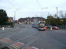
Nottingham Express Transit in the United Kingdom uses a 750 V DC overhead, in common with most modern tram systems.
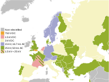
1,500 V DC is used in Japan, Indonesia, Hong Kong (parts), Republic of Ireland, Australia (parts), France (also using 25 kV 50 Hz AC), New Zealand (Wellington), Singapore (on the North East MRT Line), the United States (Chicago area on the Metra Electric district and the South Shore Line interurban line and in Seattle, Washington – Sound Transit light-rail lines). In Slovakia, there are two narrow-gauge lines in the High Tatras (one a cog railway). In the Netherlands it is used on the main system, alongside 25 kV on the HSL-Zuid and Betuwelijn, and 3000 V south of Maastricht. In Portugal, it is used in the Cascais Line and in Denmark on the suburban S-train system (1650 V DC).
In the United Kingdom, 1,500 V DC was used in 1954 for the Woodhead trans-Pennine route (now closed); the system used regenerative braking,
allowing for transfer of energy between climbing and descending trains
on the steep approaches to the tunnel. The system was also used for
suburban electrification in East London and Manchester, now converted to 25 kV AC. It is now only used for the Tyne and Wear Metro.
In India, 1,500 V DC was the first electrification system launched in
1925 in Mumbai area. Between 2012-2016, the electrification was
converted to 25 kV 50 Hz AC which is the countrywide system.
3 kV DC is used in Belgium, Italy, Spain, Poland, Slovakia, Slovenia, South Africa, Chile, the northern portion of the Czech Republic, the former republics of the Soviet Union, and the Netherlands. It was formerly used by the Milwaukee Road
from Harlowton, Montana, to Seattle-Tacoma, across the Continental
Divide and including extensive branch and loop lines in Montana, and by
the Delaware, Lackawanna & Western Railroad (now New Jersey Transit, converted to 25 kV AC) in the United States, and the Kolkata suburban railway (Bardhaman Main Line) in India, before it was converted to 25 kV 50 Hz AC.
DC voltages between 600 V and 800 V are used by most tramways (streetcars), trolleybus networks and underground (subway) systems.
Overhead systems with linear motor
Third rail
A bottom-contact third rail on the Amsterdam Metro, Netherlands
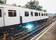
Arcs like this are normal and occur when the collection shoes of a train drawing power reach the end of a section of power rail.
Most electrification systems use overhead wires, but third rail is an option up to 1,500 V, as is the case with Shenzhen Metro Line 3.
Third rail systems exclusively use DC distribution. The use of AC is
not feasible because the dimensions of a third rail are physically very
large compared with the skin depth
that the alternating current penetrates to 0.3 millimetres or 0.012
inches in a steel rail. This effect makes the resistance per unit length
unacceptably high compared with the use of DC.
Third rail is more compact than overhead wires and can be used in
smaller-diameter tunnels, an important factor for subway systems.
Fourth rail
London Underground track at Ealing Common on the District line, showing the third and fourth rails beside and between the running rails
A train on Milan Metro's Line 1 showing the fourth-rail contact shoe.
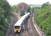
The London Underground
in England is one of the few networks that uses a four-rail system. The
additional rail carries the electrical return that, on third rail and
overhead networks, is provided by the running rails. On the London
Underground, a top-contact third rail is beside the track, energized at +420 V DC, and a top-contact fourth rail is located centrally between the running rails at −210 V DC, which combine to provide a traction voltage of 630 V DC. The same system was used for Milan's earliest underground line, Milan Metro's line 1, whose more recent lines use an overhead catenary or a third rail.
The key advantage of the four-rail system is that neither running
rail carries any current. This scheme was introduced because of the
problems of return currents, intended to be carried by the earthed (grounded)
running rail, flowing through the iron tunnel linings instead. This can
cause electrolytic damage and even arcing if the tunnel segments are
not electrically bonded
together. The problem was exacerbated because the return current also
had a tendency to flow through nearby iron pipes forming the water and
gas mains. Some of these, particularly Victorian mains that predated
London's underground railways, were not constructed to carry currents
and had no adequate electrical bonding between pipe segments. The
four-rail system solves the problem. Although the supply has an
artificially created earth point, this connection is derived by using
resistors which ensures that stray earth currents are kept to manageable
levels. Power-only rails can be mounted on strongly insulating ceramic
chairs to minimise current leak, but this is not possible for running
rails which have to be seated on stronger metal chairs to carry the
weight of trains. However, elastomeric rubber pads placed between the
rails and chairs can now solve part of the problem by insulating the
running rails from the current return should there be a leakage through
the running rails.
Linear motor
An S-series northbound train at Lawrence East station. Note the slab between the running rails.
Bombardier Innovia Metro systems run on conventional metal rails and pull power from a third rail, but are powered by a linear induction motor that provides traction by pulling on a "fourth rail" placed between the running rails.
The Vancouver SkyTrain is the largest such system in operation with just under 50 km (30 mi) of track along the Expo and Millennium lines.
In the case of Scarborough Line 3, the third and fourth rails are outside the track and the fifth rail is an aluminum slab between the running rails.
Rubber-tyred systems
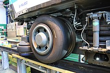
The bogie of an MP 05, showing the flanged steel wheel inside the rubber-tyred one, as well as the vertical contact shoe on top of the steel rail
Bogie from an MP 89 Paris Métro vehicle. The lateral contact shoe is located between the rubber tyres
A few lines of the Paris Métro in France operate on a four-rail power system. The trains move on rubber tyres which roll on a pair of narrow roll ways made of steel and, in some places, of concrete. Since the tyres do not conduct the return current, the two guide bars provided outside the running 'roll ways' become, in a sense, a third and fourth rail which each provide 750 V DC, so at least electrically it is a four-rail system. Each wheel set of a powered bogie carries one traction motor. A side sliding (side running) contact shoe picks up the current from the vertical face of each guide bar. The return of each traction motor, as well as each wagon, is effected by one contact shoe each that slide on top of each one of the running rails. This and all other rubber-tyred metros that have a 1,435 mm (4 ft 8 1⁄2 in) standard gauge track between the roll ways operate in the same manner.
Alternating current
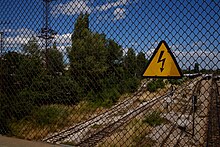
Image of a sign for high voltage above a railway electrification system
Railways and electrical utilities use AC for the same reason: to use transformers,
which require AC, to produce higher voltages.
The higher the voltage, the lower the current for the same power, which
reduces line loss, thus allowing higher power to be delivered.
Because alternating current is used with high voltages, this method of electrification is only used on overhead lines,
never on third rails. Inside the locomotive, a transformer steps the
voltage down for use by the traction motors and auxiliary loads.
An early advantage of AC is that the power-wasting resistors used in DC locomotives for speed control were not needed in an AC locomotive: multiple taps on the transformer
can supply a range of voltages.
Separate low-voltage transformer windings supply lighting and the motors
driving auxiliary machinery.
More recently, the development of very high power semiconductors has
caused the classic DC motor to be largely replaced with the three-phase induction motor fed by a variable frequency drive, a special inverter
that varies both frequency and voltage to control motor speed.
These drives can run equally well on DC or AC of any frequency, and many
modern electric locomotives are designed to handle different supply
voltages and frequencies to simplify cross-border operation.
Low-frequency alternating current
15 kV 16.7 Hz AC system used in Switzerland
Five European countries, Germany, Austria, Switzerland, Norway and Sweden, have standardized on 15 kV 16 2⁄3 Hz
(the 50 Hz mains frequency divided by three) single-phase AC. On
16 October 1995, Germany, Austria and Switzerland changed from 16 2⁄3 Hz
to 16.7 Hz which is no longer exactly one-third of the grid frequency.
This solved overheating problems with the rotary converters used to
generate some of this power from the grid supply.
In the UK, the London, Brighton and South Coast Railway pioneered overhead electrification of its suburban lines in London, London Bridge to Victoria being opened to traffic on 1 December 1909. Victoria to Crystal Palace via Balham and West Norwood opened in May 1911. Peckham Rye to West Norwood opened in June 1912. Further extensions were not made owing to the First World War. Two lines opened in 1925 under the Southern Railway serving Coulsdon North and Sutton railway station.
The lines were electrified at 6.7 kV 25 Hz. It was announced in 1926
that all lines were to be converted to DC third rail and the last
overhead electric service ran in September 1929.
Non-contact systems
It is possible to supply power to an electric train by inductive coupling. This allows the use of a high-voltage, insulated, conductor rail. Such a system was patented in 1894 by Nikola Tesla, U.S. Patent 514,972. It requires the use of high-frequency alternating current. Tesla did not specify a frequency but George Trinkaus suggests that around 1,000 Hz would be likely.
Inductive coupling is widely used in low-power applications, such as re-chargeable electric toothbrushes and more recently, mobile telephones and wearable computing devices (inductive charging).
Energy efficiency
Electric versus diesel
An early rail electrification substation at Dartford
Electric trains need not carry the weight of prime movers, transmission and fuel. This is partly offset by the weight of electrical equipment.
Regenerative braking
returns power to the electrification system so that it may be used
elsewhere, by other trains on the same system or returned to the general
power grid. This is especially useful in mountainous areas where
heavily loaded trains must descend long grades.
Central station electricity can often be generated with higher
efficiency than a mobile engine/generator. While the efficiency of power
plant generation and diesel locomotive generation are roughly the same
in the nominal regime, diesel motors decrease in efficiency in non-nominal regimes at low power
while if an electric power plant needs to generate less power it will
shut down its least efficient generators, thereby increasing efficiency.
The electric train can save energy (as compared to diesel) by regenerative braking
and by not needing to consume energy by idling as diesel locomotives do
when stopped or coasting. However, electric rolling stock may run
cooling blowers when stopped or coasting, thus consuming energy.
Large fossil fuel power stations operate at high efficiency, and can be used for district heating or to produce district cooling, leading to a higher total efficiency.
AC versus DC for mainlines
The
majority of modern electrification systems take AC energy from a power
grid that is delivered to a locomotive, and within the locomotive, transformed and rectified
to a lower DC voltage in preparation for use by traction motors. These
motors may either be DC motors which directly use the DC or they may be
3-phase AC motors which require further conversion of the DC to 3-phase
AC (using power electronics). Thus both systems are faced with the same
task: converting and transporting high-voltage AC from the power grid to
low-voltage DC in the locomotive. The difference between AC and DC
electrification systems lies in where the AC is converted to DC: at the
substation or on the train. Energy efficiency and infrastructure costs
determine which of these is used on a network, although this is often
fixed due to pre-existing electrification systems.
Both the transmission and conversion of electric energy involve
losses: ohmic losses in wires and power electronics, magnetic field
losses in transformers and smoothing reactors (inductors).
Power conversion for a DC system takes place mainly in a railway
substation where large, heavy, and more efficient hardware can be used
as compared to an AC system where conversion takes place aboard the
locomotive where space is limited and losses are significantly higher.
However, the higher voltages used in many AC electrification systems
reduces transmission losses over longer distances, allowing for fewer
substations or more powerful locomotives to be used. Also, the energy
used to blow air to cool transformers, power electronics (including
rectifiers), and other conversion hardware must be accounted for.
Comparison with diesel traction
Lots Road Power Station in a poster from 1910. This private power station, used by London Underground, gave London trains and trams a power supply independent from the main power network.
Electric locomotives may easily be constructed with greater power
output than most diesel locomotives. For passenger operation it is
possible to provide enough power with diesel engines but, at higher speeds, this proves costly and impractical. Therefore, almost all high speed trains
are electric. The high power of electric locomotives also gives them
the ability to pull freight at higher speed over gradients; in mixed
traffic conditions this increases capacity when the time between trains
can be decreased. The higher power of electric locomotives and an
electrification can also be a cheaper alternative to a new and less
steep railway if trains weights are to be increased on a system.
On the other hand, electrification may not be suitable for lines
with low frequency of traffic, because lower running cost of trains may
be outweighed by the high cost of the electrification infrastructure.
Therefore, most long-distance lines in developing or sparsely populated
countries are not electrified due to relatively low frequency of trains.
Maintenance costs of the lines may be increased by
electrification, but many systems claim lower costs due to reduced
wear-and-tear from lighter rolling stock.
There are some additional maintenance costs associated with the
electrical equipment around the track, such as power sub-stations and
the catenary wire itself, but, if there is sufficient traffic, the
reduced track and especially the lower engine maintenance and running
costs exceed the costs of this maintenance significantly.
Network effects are a large factor with electrification.
When converting lines to electric, the connections with other lines
must be considered. Some electrifications have subsequently been removed
because of the through traffic to non-electrified lines. If through traffic is to have any benefit, time consuming engine switches must occur to make such connections or expensive dual mode engines
must be used. This is mostly an issue for long distance trips, but many
lines come to be dominated by through traffic from long-haul freight
trains (usually running coal, ore, or containers to or from ports). In
theory, these trains could enjoy dramatic savings through
electrification, but it can be too costly to extend electrification to
isolated areas, and unless an entire network is electrified, companies
often find that they need to continue use of diesel trains even if
sections are electrified. The increasing demand for container traffic
which is more efficient when utilizing the double-stack car
also has network effect issues with existing electrifications due to
insufficient clearance of overhead electrical lines for these trains,
but electrification can be built or modified to have sufficient
clearance, at additional cost.
A problem specifically related to electrified lines are gaps in
the electrification. Electric vehicles, especially locomotives, lose
power when traversing gaps in the supply, such as phase change gaps in
overhead systems, and gaps over points in third rail systems. These
become a nuisance, if the locomotive stops with its collector on a dead
gap, in which case there is no power to restart. Power gaps can be
overcome by on-board batteries or motor-flywheel-generator systems.[citation needed]
In 2014, progress is being made in the use of large capacitors to power electric vehicles between stations, and so avoid the need for overhead wires between those stations.
Advantages
- No exposure to passengers to exhaust from the locomotive
- Lower cost of building, running and maintaining locomotives and multiple units
- Higher power-to-weight ratio (no onboard fuel tanks), resulting in
- Fewer locomotives
- Faster acceleration
- Higher practical limit of power
- Higher limit of speed
- Less noise pollution (quieter operation)
- Faster acceleration clears lines more quickly to run more trains on the track in urban rail uses
- Reduced power loss at higher altitudes (for power loss see Diesel engine)
- Independence of running costs from fluctuating fuel prices
- Service to underground stations where diesel trains cannot operate for safety reasons
- Reduced environmental pollution, especially in highly populated urban areas, even if electricity is produced by fossil fuels
- Easily accommodates kinetic energy brake reclaim using supercapacitors
- More comfortable ride on multiple units as trains have no underfloor diesel engines
- Somewhat higher energy efficiency in part due to regenerative braking and less power lost when "idling"
- More flexible primary energy source: can use coal, nuclear, hydro or wind as the primary energy source instead of oil
Disadvantages
The Royal Border Bridge in England, a protected monument. Adding electric catenary to older structures may be an expensive cost of electrification projects
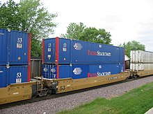
Most overhead electrifications do not allow sufficient clearance for a double-stack car. Each container may be 9 ft 6 in (2.90 m) tall and the bottom of the well is 1 ft 2 in (0.36 m) above rail, making the overall height 20 ft 2 in (6.15 m) including the well car.
- Electrification cost: electrification requires an entire new infrastructure to be built around the existing tracks at a significant cost. Costs are especially high when tunnels, bridges and other obstructions have to be altered for clearance. Another aspect that can raise the cost of electrification are the alterations or upgrades to railway signalling needed for new traffic characteristics, and to protect signalling circuitry and track circuits from interference by traction current. Electrification may require line closures while the new equipment is being installed.
- Appearance: the overhead line structures and cabling can have a significant landscape impact compared with a non-electrified or third rail electrified line that has only occasional signalling equipment above ground level.
- Fragility and vulnerability: overhead electrification systems can suffer severe disruption due to minor mechanical faults or the effects of high winds causing the pantograph of a moving train to become entangled with the catenary, ripping the wires from their supports. The damage is often not limited to the supply to one track, but extends to those for adjacent tracks as well, causing the entire route to be blocked for a considerable time. Third-rail systems can suffer disruption in cold weather due to ice forming on the conductor rail.
- Theft: the high scrap value of copper and the unguarded, remote installations make overhead cables an attractive target for scrap metal thieves. Attempts at theft of live 25 kV cables may end in the thief's death from electrocution. In the UK, cable theft is claimed to be one of the biggest sources of delay and disruption to train services — though this normally relates to signalling cable, which is equally problematic for diesel lines.
- Birds may perch on parts with different charges, and animals may also touch the electrification system. Dead animals attract foxes or other predators, bringing risk of collision with trains.
- In most of the world's railway networks, the height clearance of overhead electrical lines is not sufficient for a double-stack container car or other unusually tall loads. It is extremely costly to upgrade electrified lines to the correct clearances (21 ft 8 in or 6.60 m) to take double-stacked container trains.


