Search This Blog

Thursday, December 6, 2018

Space elevator (updated)

From Wikipedia, the free encyclopedia

Diagram of a space elevator. At the bottom of the tall diagram is the Earth as viewed from high above the North Pole. About six earth-radii above the Earth an arc is drawn with the same center as the Earth. The arc depicts the level of geosynchronous orbit. About twice as high as the arc and directly above the Earth's center, a counterweight is depicted by a small square. A line depicting the space elevator's cable connects the counterweight to the equator directly below it. The system's center of mass is described as above the level of geosynchronous orbit. The center of mass is shown roughly to be about a quarter of the way up from the geosynchronous arc to the counterweight. The bottom of the cable is indicated to be anchored at the equator. A climber is depicted by a small rounded square. The climber is shown climbing the cable about one third of the way from the ground to the arc. Another note indicates that the cable rotates along with the Earth's daily rotation, and remains vertical.
A space elevator is conceived as a cable fixed to the equator and reaching into space. A counterweight at the upper end keeps the center of mass well above geostationary orbit level. This produces enough upward centrifugal force from Earth's rotation to fully counter the downward gravity, keeping the cable upright and taut. Climbers carry cargo up and down the cable.
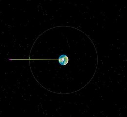
 
Space elevator in motion rotating with Earth, viewed from above North Pole. A free-flying satellite (green dot) is shown in geostationary orbit slightly behind the cable.

A space elevator is a proposed type of planet-to-space transportation system. The main component would be a cable (also called a tether) anchored to the surface and extending into space. The design would permit vehicles to travel along the cable from a planetary surface, such as the Earth's, directly into space or orbit, without the use of large rockets. An Earth-based space elevator would consist of a cable with one end attached to the surface near the equator and the other end in space beyond geostationary orbit (35,786 km altitude). The competing forces of gravity, which is stronger at the lower end, and the outward/upward centrifugal force, which is stronger at the upper end, would result in the cable being held up, under tension, and stationary over a single position on Earth. With the tether deployed, climbers could repeatedly climb the tether to space by mechanical means, releasing their cargo to orbit. Climbers could also descend the tether to return cargo to the surface from orbit.

The concept of a tower reaching geosynchronous orbit was first published in 1895 by Konstantin Tsiolkovsky. His proposal was for a free-standing tower reaching from the surface of Earth to the height of geostationary orbit. Like all buildings, Tsiolkovsky's structure would be under compression, supporting its weight from below. Since 1959, most ideas for space elevators have focused on purely tensile structures, with the weight of the system held up from above by centrifugal forces. In the tensile concepts, a space tether reaches from a large mass (the counterweight) beyond geostationary orbit to the ground. This structure is held in tension between Earth and the counterweight like an upside-down plumb bob.

To construct a space elevator on Earth, the cable material would need to be both stronger and lighter (have greater specific strength) than any known material. Development of new materials that meet the demanding specific strength requirement must happen before designs can progress beyond discussion stage. Carbon nanotubes (CNTs) have been identified as possibly being able to meet the specific strength requirements for an Earth space elevator. Other materials considered have been boron nitride nanotubes, and diamond nanothreads, which were first constructed in 2014.

A prototype was launched in 2018 to tether to future stations as well as the International Space Station. It is a miniature version to be further examined before making the decision to build up a large structure in the coming years. 

The concept is applicable to other planets and celestial bodies. For locations in the solar system with weaker gravity than Earth's (such as the Moon or Mars), the strength-to-density requirements for tether materials are not as problematic. Currently available materials (such as Kevlar) are strong and light enough that they could be used as the tether material for elevators there.

History

Early concepts


The key concept of the space elevator appeared in 1895 when Russian scientist Konstantin Tsiolkovsky was inspired by the Eiffel Tower in Paris. He considered a similar tower that reached all the way into space and was built from the ground up to the altitude of 35,786 kilometers, the height of geostationary orbit. He noted that the top of such a tower would be circling Earth as in a geostationary orbit. Objects would attain horizontal velocity as they rode up the tower, and an object released at the tower's top would have enough horizontal velocity to remain there in geostationary orbit. Tsiolkovsky's conceptual tower was a compression structure, while modern concepts call for a tensile structure (or "tether").

20th century

Building a compression structure from the ground up proved an unrealistic task as there was no material in existence with enough compressive strength to support its own weight under such conditions. In 1959 another Russian scientist, Yuri N. Artsutanov, suggested a more feasible proposal. Artsutanov suggested using a geostationary satellite as the base from which to deploy the structure downward. By using a counterweight, a cable would be lowered from geostationary orbit to the surface of Earth, while the counterweight was extended from the satellite away from Earth, keeping the cable constantly over the same spot on the surface of the Earth. Artsutanov's idea was introduced to the Russian-speaking public in an interview published in the Sunday supplement of Komsomolskaya Pravda in 1960, but was not available in English until much later. He also proposed tapering the cable thickness so that the stress in the cable was constant. This gave a thinner cable at ground level that became thickest at the level of geostationary orbit.

Both the tower and cable ideas were proposed in the quasi-humorous Ariadne column in New Scientist, December 24, 1964.

In 1966, Isaacs, Vine, Bradner and Bachus, four American engineers, reinvented the concept, naming it a "Sky-Hook", and published their analysis in the journal Science. They decided to determine what type of material would be required to build a space elevator, assuming it would be a straight cable with no variations in its cross section, and found that the strength required would be twice that of any then-existing material including graphite, quartz, and diamond.

In 1975 an American scientist, Jerome Pearson, reinvented the concept yet again, publishing his analysis in the journal Acta Astronautica. He designed a tapered cross section that would be better suited to building the elevator. The completed cable would be thickest at the geostationary orbit, where the tension was greatest, and would be narrowest at the tips to reduce the amount of weight per unit area of cross section that any point on the cable would have to bear. He suggested using a counterweight that would be slowly extended out to 144,000 kilometers (89,000 miles), almost half the distance to the Moon as the lower section of the elevator was built. Without a large counterweight, the upper portion of the cable would have to be longer than the lower due to the way gravitational and centrifugal forces change with distance from Earth. His analysis included disturbances such as the gravitation of the Moon, wind and moving payloads up and down the cable. The weight of the material needed to build the elevator would have required thousands of Space Shuttle trips, although part of the material could be transported up the elevator when a minimum strength strand reached the ground or be manufactured in space from asteroidal or lunar ore.

After the development of carbon nanotubes in the 1990s, engineer David Smitherman of NASA/Marshall's Advanced Projects Office realized that the high strength of these materials might make the concept of a space elevator feasible, and put together a workshop at the Marshall Space Flight Center, inviting many scientists and engineers to discuss concepts and compile plans for an elevator to turn the concept into a reality.

In 2000, another American scientist, Bradley C. Edwards, suggested creating a 100,000 km (62,000 mi) long paper-thin ribbon using a carbon nanotube composite material. He chose the wide-thin ribbon-like cross-section shape rather than earlier circular cross-section concepts because that shape would stand a greater chance of surviving impacts by meteoroids. The ribbon cross-section shape also provided large surface area for climbers to climb with simple rollers. Supported by the NASA Institute for Advanced Concepts, Edwards' work was expanded to cover the deployment scenario, climber design, power delivery system, orbital debris avoidance, anchor system, surviving atomic oxygen, avoiding lightning and hurricanes by locating the anchor in the western equatorial Pacific, construction costs, construction schedule, and environmental hazards.

21st century

To speed space elevator development, proponents have organized several competitions, similar to the Ansari X Prize, for relevant technologies. Among them are Elevator:2010, which organized annual competitions for climbers, ribbons and power-beaming systems from 2005 to 2009, the Robogames Space Elevator Ribbon Climbing competition, as well as NASA's Centennial Challenges program, which, in March 2005, announced a partnership with the Spaceward Foundation (the operator of Elevator:2010), raising the total value of prizes to US$400,000. The first European Space Elevator Challenge (EuSEC) to establish a climber structure took place in August 2011.

In 2005, "the LiftPort Group of space elevator companies announced that it will be building a carbon nanotube manufacturing plant in Millville, New Jersey, to supply various glass, plastic and metal companies with these strong materials. Although LiftPort hopes to eventually use carbon nanotubes in the construction of a 100,000 km (62,000 mi) space elevator, this move will allow it to make money in the short term and conduct research and development into new production methods." Their announced goal was a space elevator launch in 2010. On February 13, 2006 the LiftPort Group announced that, earlier the same month, they had tested a mile of "space-elevator tether" made of carbon-fiber composite strings and fiberglass tape measuring 5 cm (2.0 in) wide and 1 mm (approx. 13 sheets of paper) thick, lifted with balloons.

In 2007, Elevator:2010 held the 2007 Space Elevator games, which featured US$500,000 awards for each of the two competitions, ($1,000,000 total) as well as an additional $4,000,000 to be awarded over the next five years for space elevator related technologies. No teams won the competition, but a team from MIT entered the first 2-gram (0.07 oz), 100-percent carbon nanotube entry into the competition. Japan held an international conference in November 2008 to draw up a timetable for building the elevator.

In 2008 the book Leaving the Planet by Space Elevator by Dr. Brad Edwards and Philip Ragan was published in Japanese and entered the Japanese best-seller list. This led to Shuichi Ono, chairman of the Japan Space Elevator Association, unveiling a space-elevator plan, putting forth what observers considered an extremely low cost estimate of a trillion yen (£5 billion / $8 billion) to build one.

In 2012, the Obayashi Corporation announced that in 38 years it could build a space elevator using carbon nanotube technology. At 200 kilometers per hour, the design's 30-passenger climber would be able to reach the GEO level after a 7.5 day trip. No cost estimates, finance plans, or other specifics were made. This, along with timing and other factors, hinted that the announcement was made largely to provide publicity for the opening of one of the company's other projects in Tokyo.

In 2013, the International Academy of Astronautics published a technological feasibility assessment which concluded that the critical capability improvement needed was the tether material, which was projected to achieve the necessary strength-to-weight ratio within 20 years. The four-year long study looked into many facets of space elevator development including missions, development schedules, financial investments, revenue flow, and benefits. It was reported that it would be possible to operationally survive smaller impacts and avoid larger impacts, with meteors and space debris, and that the estimated cost of lifting a kilogram of payload to GEO and beyond would be $500.

In 2014, Google X's Rapid Evaluation R&D team began the design of a Space Elevator, eventually finding that no one had yet manufactured a perfectly formed carbon nanotube strand longer than a meter. They thus decided to put the project in "deep freeze" and also keep tabs on any advances in the carbon nanotube field.

In 2018, researchers at Japan's Shizuoka University launched a mini-elevator consisting of two cube stats and a tether. The prototype was launched as a test bed for a larger structure.

In fiction

In 1979, space elevators were introduced to a broader audience with the simultaneous publication of Arthur C. Clarke's novel, The Fountains of Paradise, in which engineers construct a space elevator on top of a mountain peak in the fictional island country of "Taprobane" (loosely based on Sri Lanka, albeit moved south to the Equator), and Charles Sheffield's first novel, The Web Between the Worlds, also featuring the building of a space elevator. Three years later, in Robert A. Heinlein's 1982 novel Friday the principal character makes use of the "Nairobi Beanstalk" in the course of her travels. In Kim Stanley Robinson's 1993 novel Red Mars, colonists build a space elevator on Mars that allows both for more colonists to arrive and also for natural resources mined there to be able to leave for Earth. In David Gerrold's 2000 novel, Jumping Off The Planet, a family excursion up the Ecuador "beanstalk" is actually a child-custody kidnapping. Gerrold's book also examines some of the industrial applications of a mature elevator technology. In a biological version, Joan Slonczewski's 2011 novel The Highest Frontier depicts a college student ascending a space elevator constructed of self-healing cables of anthrax bacilli. The engineered bacteria can regrow the cables when severed by space debris.

Physics

Apparent gravitational field

A space elevator cable rotates along with the rotation of the Earth. Therefore, objects attached to the cable would experience upward centrifugal force in the direction opposing the downward gravitational force. The higher up the cable the object is located, the less the gravitational pull of the Earth, and the stronger the upward centrifugal force due to the rotation, so that more centrifugal force opposes less gravity. The centrifugal force and the gravity are balanced at geosynchronous equatorial orbit (GEO). Above GEO, the centrifugal force is stronger than gravity, causing objects attached to the cable there to pull upward on it. 

The net force for objects attached to the cable is called the apparent gravitational field. The apparent gravitational field for attached objects is the (downward) gravity minus the (upward) centrifugal force. The apparent gravity experienced by an object on the cable is zero at GEO, downward below GEO, and upward above GEO. 

The apparent gravitational field can be represented this way:
The downward force of actual gravity decreases with height:
The upward centrifugal force due to the planet's rotation increases with height:
Together, the apparent gravitational field is the sum of the two: .
where
g is the acceleration of apparent gravity, pointing down (negative) or up (positive) along the vertical cable (m s−2),
gr is the gravitational acceleration due to Earth's pull, pointing down (negative)(m s−2),
a is the centrifugal acceleration, pointing up (positive) along the vertical cable (m s−2),
G is the gravitational constant (m3 s−2 kg−1)
M is the mass of the Earth (kg)
r is the distance from that point to Earth's center (m),
ω is Earth's rotation speed (radian/s).

At some point up the cable, the two terms (downward gravity and upward centrifugal force) are equal and opposite. Objects fixed to the cable at that point put no weight on the cable. This altitude (r1) depends on the mass of the planet and its rotation rate. Setting actual gravity equal to centrifugal acceleration gives:


On Earth, this distance is 35,786 km (22,236 mi) above the surface, the altitude of geostationary orbit.

On the cable below geostationary orbit, downward gravity would be greater than the upward centrifugal force, so the apparent gravity would pull objects attached to the cable downward. Any object released from the cable below that level would initially accelerate downward along the cable. Then gradually it would deflect eastward from the cable. On the cable above the level of stationary orbit, upward centrifugal force would be greater than downward gravity, so the apparent gravity would pull objects attached to the cable upward. Any object released from the cable above the geosynchronous level would initially accelerate upward along the cable. Then gradually it would deflect westward from the cable.

Cable section

Historically, the main technical problem has been considered the ability of the cable to hold up, with tension, the weight of itself below any given point. The greatest tension on a space elevator cable is at the point of geostationary orbit, 35,786 km (22,236 mi) above the Earth's equator. This means that the cable material, combined with its design, must be strong enough to hold up its own weight from the surface up to 35,786 km (22,236 mi). A cable which is thicker in cross section at that height than at the surface could better hold up its own weight over a longer length. How the cross section area tapers from the maximum at 35,786 km (22,236 mi) to the minimum at the surface is therefore an important design factor for a space elevator cable. 

To maximize the usable excess strength for a given amount of cable material, the cable's cross section area would need to be designed for the most part in such a way that the stress (i.e., the tension per unit of cross sectional area) is constant along the length of the cable. The constant-stress criterion is a starting point in the design of the cable cross section as it changes with altitude. Other factors considered in more detailed designs include thickening at altitudes where more space junk is present, consideration of the point stresses imposed by climbers, and the use of varied materials. To account for these and other factors, modern detailed cross section designs seek to achieve the largest safety margin possible, with as little variation over altitude and time as possible. In simple starting-point designs, that equates to constant-stress. 

In the constant-stress case, the cross-section follows this differential equation:

or
or
where
g is the acceleration along the radius (m·s−2),
S is the cross-section area of the cable at any given point r, (m2) and dS its variation (m2 as well),
ρ is the density of the material used for the cable (kg·m−3).
σ is the stress the cross-section area can bear without yielding (N·m−2=kg·m−1·s−2), its elastic limit.
 
The value of g is given by the first equation, which yields: 

,

The variation being taken between r0 (ground) and r1 (geostationary).

Between these two points, this quantity can be expressed as: 

or

where is the ratio between the centrifugal force on the equator and the gravitational force.

Cable material

To compare materials, the specific strength of the material for the space elevator can be expressed in terms of the characteristic length, or "free breaking length": the length of an un-tapered cylindrical cable at which it will break under its own weight under constant gravity. For a given material, that length is , where , and are as defined above. 

The free breaking length needed is given by the equation 

.

For a space elevator with a material with , the section at the synchronous orbit needs to be times as much as at ground level. For a space elevator with a material with , the section at the synchronous orbit needs to be times as much as at ground level.

Structure

One concept for the space elevator has it tethered to a mobile seagoing platform.

There are a variety of space elevator designs. Almost every design includes a base station, a cable, climbers, and a counterweight. Earth's rotation creates upward centrifugal force on the counterweight. The counterweight is held down by the cable while the cable is held up and taut by the counterweight. The base station anchors the whole system to the surface of the Earth. Climbers climb up and down the cable with cargo.

Base station

Modern concepts for the base station/anchor are typically mobile stations, large oceangoing vessels or other mobile platforms. Mobile base stations would have the advantage over the earlier stationary concepts (with land-based anchors) by being able to maneuver to avoid high winds, storms, and space debris. Oceanic anchor points are also typically in international waters, simplifying and reducing cost of negotiating territory use for the base station.

Stationary land based platforms would have simpler and less costly logistical access to the base. They also would have an advantage of being able to be at high altitude, such as on top of mountains. In an alternate concept, the base station could be a tower, forming a space elevator which comprises both a compression tower close to the surface, and a tether structure at higher altitudes. Combining a compression structure with a tension structure would reduce loads from the atmosphere at the Earth end of the tether, and reduce the distance into the Earth's gravity field the cable needs to extend, and thus reduce the critical strength-to-density requirements for the cable material, all other design factors being equal.

Cable

Carbon nanotubes are one of the candidates for a cable material
 
A seagoing anchor station would also act as a deep-water seaport.

A space elevator cable would need to carry its own weight as well as the additional weight of climbers. The required strength of the cable would vary along its length. This is because at various points it would have to carry the weight of the cable below, or provide a downward force to retain the cable and counterweight above. Maximum tension on a space elevator cable would be at geosynchronous altitude so the cable would have to be thickest there and taper carefully as it approaches Earth. Any potential cable design may be characterized by the taper factor – the ratio between the cable's radius at geosynchronous altitude and at the Earth's surface.

The cable would need to be made of a material with a large tensile strength/density ratio. For example, the Edwards space elevator design assumes a cable material with a specific strength of at least 100,000 kN/(kg/m). This value takes into consideration the entire weight of the space elevator. An untapered space elevator cable would need a material capable of sustaining a length of 4,960 kilometers (3,080 mi) of its own weight at sea level to reach a geostationary altitude of 35,786 km (22,236 mi) without yielding. Therefore, a material with very high strength and lightness is needed.

For comparison, metals like titanium, steel or aluminium alloys have breaking lengths of only 20–30 km. Modern fibre materials such as kevlar, fibreglass and carbon/graphite fibre have breaking lengths of 100–400 km. Nanoengineered materials such as carbon nanotubes and, more recently discovered, graphene ribbons (perfect two-dimensional sheets of carbon) are expected to have breaking lengths of 5000–6000 km at sea level, and also are able to conduct electrical power.

For a space elevator on Earth, with its comparatively high gravity, the cable material would need to be stronger and lighter than currently available materials. For this reason, there has been a focus on the development of new materials that meet the demanding specific strength requirement. For high specific strength, carbon has advantages because it is only the 6th element in the periodic table. Carbon has comparatively few of the protons and neutrons which contribute most of the dead weight of any material. Most of the interatomic bonding forces of any element are contributed by only the outer few electrons. For carbon, the strength and stability of those bonds is high compared to the mass of the atom. The challenge in using carbon nanotubes remains to extend to macroscopic sizes the production of such material that are still perfect on the microscopic scale (as microscopic defects are most responsible for material weakness). As of 2014, carbon nanotube technology allowed growing tubes up to a few tenths of meters.

In 2014, diamond nanothreads were first synthesized. Since they have strength properties similar to carbon nanotubes, diamond nanothreads were quickly seen as candidate cable material as well.

Climbers

A conceptual drawing of a space elevator climber ascending through the clouds.

A space elevator cannot be an elevator in the typical sense (with moving cables) due to the need for the cable to be significantly wider at the center than at the tips. While various designs employing moving cables have been proposed, most cable designs call for the "elevator" to climb up a stationary cable.

Climbers cover a wide range of designs. On elevator designs whose cables are planar ribbons, most propose to use pairs of rollers to hold the cable with friction.

Climbers would need to be paced at optimal timings so as to minimize cable stress and oscillations and to maximize throughput. Lighter climbers could be sent up more often, with several going up at the same time. This would increase throughput somewhat, but would lower the mass of each individual payload.

As the car climbs, the cable takes on a slight lean due to the Coriolis force. The top of the cable travels faster than the bottom. The climber is accelerated horizontally as it ascends by the Coriolis force which is imparted by angles of the cable. The lean-angle shown is exaggerated.

The horizontal speed, i.e. due to orbital rotation, of each part of the cable increases with altitude, proportional to distance from the center of the Earth, reaching low orbital speed at a point approximately 66 percent of the height between the surface and geostationary orbit, or a height of about 23,400 km. A payload released at this point would go into a highly eccentric elliptical orbit, staying just barely clear from atmospheric reentry, with the periapsis at the same altitude as LEO and the apoapsis at the release height. With increasing release height the orbit would become less eccentric as both periapsis and apoapsis increase, becoming circular at geostationary level. When the payload has reached GEO, the horizontal speed is exactly the speed of a circular orbit at that level, so that if released, it would remain adjacent to that point on the cable. The payload can also continue climbing further up the cable beyond GEO, allowing it to obtain higher speed at jettison. If released from 100,000 km, the payload would have enough speed to reach the asteroid belt.

As a payload is lifted up a space elevator, it would gain not only altitude, but horizontal speed (angular momentum) as well. The angular momentum is taken from the Earth's rotation. As the climber ascends, it is initially moving slower than each successive part of cable it is moving on to. This is the Coriolis force: the climber "drags" (westward) on the cable, as it climbs, and slightly decreases the Earth's rotation speed. The opposite process would occur for descending payloads: the cable is tilted eastward, thus slightly increasing Earth's rotation speed. 

The overall effect of the centrifugal force acting on the cable would cause it to constantly try to return to the energetically favorable vertical orientation, so after an object has been lifted on the cable, the counterweight would swing back toward the vertical like an inverted pendulum. Space elevators and their loads would be designed so that the center of mass is always well-enough above the level of geostationary orbit to hold up the whole system. Lift and descent operations would need to be carefully planned so as to keep the pendulum-like motion of the counterweight around the tether point under control.

Climber speed would be limited by the Coriolis force, available power, and by the need to ensure the climber's accelerating force does not break the cable. Climbers would also need to maintain a minimum average speed in order to move material up and down economically and expeditiously. At the speed of a very fast car or train of 300 km/h (190 mph) it will take about 5 days to climb to geosynchronous orbit.

Powering climbers

Both power and energy are significant issues for climbers—the climbers would need to gain a large amount of potential energy as quickly as possible to clear the cable for the next payload.

Various methods have been proposed to get that energy to the climber:
  • Transfer the energy to the climber through wireless energy transfer while it is climbing.
  • Transfer the energy to the climber through some material structure while it is climbing.
  • Store the energy in the climber before it starts – requires an extremely high specific energy such as nuclear energy.
  • Solar power – After the first 40 km it is possible to use solar energy to power the climber
Wireless energy transfer such as laser power beaming is currently considered the most likely method, using megawatt powered free electron or solid state lasers in combination with adaptive mirrors approximately 10 m (33 ft) wide and a photovoltaic array on the climber tuned to the laser frequency for efficiency. For climber designs powered by power beaming, this efficiency is an important design goal. Unused energy would need to be re-radiated away with heat-dissipation systems, which add to weight.

Yoshio Aoki, a professor of precision machinery engineering at Nihon University and director of the Japan Space Elevator Association, suggested including a second cable and using the conductivity of carbon nanotubes to provide power.

Counterweight

Space Elevator with Space Station

Several solutions have been proposed to act as a counterweight:
  • a heavy, captured asteroid;
  • a space dock, space station or spaceport positioned past geostationary orbit
  • a further upward extension of the cable itself so that the net upward pull would be the same as an equivalent counterweight;
  • parked spent climbers that had been used to thicken the cable during construction, other junk, and material lifted up the cable for the purpose of increasing the counterweight.
Extending the cable has the advantage of some simplicity of the task and the fact that a payload that went to the end of the counterweight-cable would acquire considerable velocity relative to the Earth, allowing it to be launched into interplanetary space. Its disadvantage is the need to produce greater amounts of cable material as opposed to using just anything available that has mass.

Launching into deep space

An object attached to a space elevator at a radius of approximately 53,100 km would be at escape velocity when released. Transfer orbits to the L1 and L2 Lagrangian points could be attained by release at 50,630 and 51,240 km, respectively, and transfer to lunar orbit from 50,960 km.

At the end of Pearson's 144,000 km (89,000 mi) cable, the tangential velocity is 10.93 kilometers per second (6.79 mi/s). That is more than enough to escape Earth's gravitational field and send probes at least as far out as Jupiter. Once at Jupiter, a gravitational assist maneuver could permit solar escape velocity to be reached.

Extraterrestrial elevators

A space elevator could also be constructed on other planets, asteroids and moons.

A Martian tether could be much shorter than one on Earth. Mars' surface gravity is 38 percent of Earth's, while it rotates around its axis in about the same time as Earth. Because of this, Martian stationary orbit is much closer to the surface, and hence the elevator could be much shorter. Current materials are already sufficiently strong to construct such an elevator. Building a Martian elevator would be complicated by the Martian moon Phobos, which is in a low orbit and intersects the Equator regularly (twice every orbital period of 11 h 6 min).

On the near side of the Moon, the strength-to-density required of the tether of a lunar space elevator exists in currently available materials. A lunar space elevator would be about 50,000 kilometers (31,000 mi) long. Since the Moon does not rotate fast enough, there is no effective lunar-stationary orbit, but the Lagrangian points could be used. The near side would extend through the Earth-Moon L1 point from an anchor point near the center of the visible part of Earth's Moon.

On the far side of the Moon, a lunar space elevator would need to be very long—more than twice the length of an Earth elevator—but due to the low gravity of the Moon, could also be made of existing engineering materials.

Rapidly spinning asteroids or moons could use cables to eject materials to convenient points, such as Earth orbits; or conversely, to eject materials to send a portion of the mass of the asteroid or moon to Earth orbit or a Lagrangian point. Freeman Dyson, a physicist and mathematician, has suggested using such smaller systems as power generators at points distant from the Sun where solar power is uneconomical.

A space elevator using presently available engineering materials could be constructed between mutually tidally locked worlds, such as Pluto and Charon or the components of binary asteroid 90 Antiope, with no terminus disconnect, according to Francis Graham of Kent State University. However, spooled variable lengths of cable must be used due to ellipticity of the orbits.

Construction

The construction of a space elevator would need reduction of some technical risk. Some advances in engineering, manufacturing and physical technology are required. Once a first space elevator is built, the second one and all others would have the use of the previous ones to assist in construction, making their costs considerably lower. Such follow-on space elevators would also benefit from the great reduction in technical risk achieved by the construction of the first space elevator.

Prior to the work of Edwards in 2000 most concepts for constructing a space elevator had the cable manufactured in space. That was thought to be necessary for such a large and long object and for such a large counterweight. Manufacturing the cable in space would be done in principle by using an asteroid or Near-Earth object for source material. These earlier concepts for construction require a large preexisting space-faring infrastructure to maneuver an asteroid into its needed orbit around Earth. They also required the development of technologies for manufacture in space of large quantities of exacting materials.

Since 2001, most work has focused on simpler methods of construction requiring much smaller space infrastructures. They conceive the launch of a long cable on a large spool, followed by deployment of it in space. The spool would be initially parked in a geostationary orbit above the planned anchor point. A long cable would be dropped "downward" (toward Earth) and would be balanced by a mass being dropped "upward" (away from Earth) for the whole system to remain on the geosynchronous orbit. Earlier designs imagined the balancing mass to be another cable (with counterweight) extending upward, with the main spool remaining at the original geosynchronous orbit level. Most current designs elevate the spool itself as the main cable is paid out, a simpler process. When the lower end of the cable is long enough to reach the surface of the Earth (at the equator), it would be anchored. Once anchored, the center of mass would be elevated more (by adding mass at the upper end or by paying out more cable). This would add more tension to the whole cable, which could then be used as an elevator cable.

One plan for construction uses conventional rockets to place a "minimum size" initial seed cable of only 19,800 kg. This first very small ribbon would be adequate to support the first 619 kg climber. The first 207 climbers would carry up and attach more cable to the original, increasing its cross section area and widening the initial ribbon to about 160 mm wide at its widest point. The result would be a 750-ton cable with a lift capacity of 20 tons per climber.

Safety issues and construction challenges

For early systems, transit times from the surface to the level of geosynchronous orbit would be about five days. On these early systems, the time spent moving through the Van Allen radiation belts would be enough that passengers would need to be protected from radiation by shielding, which would add mass to the climber and decrease payload.

A space elevator would present a navigational hazard, both to aircraft and spacecraft. Aircraft could be diverted by air-traffic control restrictions. All objects in stable orbits that have perigee below the maximum altitude of the cable that are not synchronous with the cable would impact the cable eventually, unless avoiding action is taken. One potential solution proposed by Edwards is to use a movable anchor (a sea anchor) to allow the tether to "dodge" any space debris large enough to track.

Impacts by space objects such as meteoroids, micrometeorites and orbiting man-made debris pose another design constraint on the cable. A cable would need to be designed to maneuver out of the way of debris, or absorb impacts of small debris without breaking.

Economics

With a space elevator, materials might be sent into orbit at a fraction of the current cost. As of 2000, conventional rocket designs cost about US$25,000 per kilogram (US$11,000 per pound) for transfer to geostationary orbit. Current space elevator proposals envision payload prices starting as low as $220 per kilogram ($100 per pound), similar to the $5–$300/kg estimates of the Launch loop, but higher than the $310/ton to 500 km orbit quoted to Dr. Jerry Pournelle for an orbital airship system.

Philip Ragan, co-author of the book Leaving the Planet by Space Elevator, states that "The first country to deploy a space elevator will have a 95 percent cost advantage and could potentially control all space activities."

International Space Elevator Consortium (ISEC)

The International Space Elevator Consortium (ISEC) was formed to promote the development, construction, and operation of a space elevator as "a revolutionary and efficient way to space for all humanity". It was formed after the Space Elevator Conference in Redmond, Washington in July 2008 and became an affiliate organization with the National Space Society in August 2013.

ISEC coordinates with the two other major societies focusing on space elevators: the Japanese Space Elevator Association and EuroSpaceward. ISEC supports symposia and presentations at the International Academy of Astronautics and the International Astronautical Federation Congress each year. The organization published two issues of a peer-reviewed journal on space elevators called "CLIMB".

ISEC also conducts one-year studies focusing on individual topics. The process involves experts for one year of discussions on the topic of choice and culminates in a draft report that is presented and reviewed at the ISEC Space Elevator conference workshop. This review of the major conclusions allows input from space elevator enthusiasts as well as other experts. Topics that have concluded are: 2010 - Space Elevator Survivability, Space Debris Mitigation, 2012 - Space Elevator Concept of Operations, 2013 - Design Consideration for Tether Climbers,, 2014 - Space Elevator Architectures and Roadmaps. 2015 - Design Characteristics of a Space Elevator Earth Port, 2017 - Design Considerations for the Space Elevator Apex Anchor and GEO Node.

Related concepts

The conventional current concept of a "Space Elevator" has evolved from a static compressive structure reaching to the level of GEO, to the modern baseline idea of a static tensile structure anchored to the ground and extending to well above the level of GEO. In the current usage by practitioners (and in this article), a "Space Elevator" means the Tsiolkovsky-Artsutanov-Pearson type as considered by the International Space Elevator Consortium. This conventional type is a static structure fixed to the ground and extending into space high enough that cargo can climb the structure up from the ground to a level where simple release will put the cargo into an orbit.

Some concepts related to this modern baseline are not usually termed a "Space Elevator", but are similar in some way and are sometimes termed "Space Elevator" by their proponents. For example, Hans Moravec published an article in 1977 called "A Non-Synchronous Orbital Skyhook" describing a concept using a rotating cable. The rotation speed would exactly match the orbital speed in such a way that the tip velocity at the lowest point was zero compared to the object to be "elevated". It would dynamically grapple and then "elevate" high flying objects to orbit or low orbiting objects to higher orbit. 

The original concept envisioned by Tsiolkovsky was a compression structure, a concept similar to an aerial mast. While such structures might reach space (100 km, 62 mi), they are unlikely to reach geostationary orbit. The concept of a Tsiolkovsky tower combined with a classic space elevator cable (reaching above the level of GEO) has been suggested. Other ideas use very tall compressive towers to reduce the demands on launch vehicles. The vehicle is "elevated" up the tower, which may extend as high as above the atmosphere, and is launched from the top. Such a tall tower to access near-space altitudes of 20 km (12 mi) has been proposed by various researchers.

Other concepts for non-rocket spacelaunch related to a space elevator (or parts of a space elevator) include an orbital ring, a pneumatic space tower, a space fountain, a launch loop, a skyhook, a space tether, and a buoyant "SpaceShaft".

Potential applications of carbon nanotubes

From Wikipedia, the free encyclopedia
Carbon nanotubes (CNTs) are cylinders of one or more layers of graphene (lattice). Diameters of single-walled carbon nanotubes (SWNTs) and multi-walled carbon nanotubes (MWNTs) are typically 0.8 to 2 nm and 5 to 20 nm, respectively, although MWNT diameters can exceed 100 nm. CNT lengths range from less than 100 nm to 0.5 m.

Individual CNT walls can be metallic or semiconducting depending on the orientation of the lattice with respect to the tube axis, which is called chirality. MWNT's cross-sectional area offers an elastic modulus approaching 1 TPa and a tensile strength of 100 GPa, over 10-fold higher than any industrial fiber. MWNTs are typically metallic and can carry currents of up to 109 A cm−2. SWNTs can display thermal conductivity of 3500 W m−1 K−1, exceeding that of diamond.

As of 2013, carbon nanotube production exceeded several thousand tons per year, used for applications in energy storage, device modelling, automotive parts, boat hulls, sporting goods, water filters, thin-film electronics, coatings, actuators and electromagnetic shields. CNT-related publications more than tripled in the prior decade, while rates of patent issuance also increased. Most output was of unorganized architecture. Organized CNT architectures such as "forests", yarns and regular sheets were produced in much smaller volumes. CNTs have even been proposed as the tether for a purported space elevator.

3D carbon nanotube scaffolds

Recently, several studies have highlighted the prospect of using carbon nanotubes as building blocks to fabricate three-dimensional macroscopic (>1mm in all three dimensions) all-carbon devices. Lalwani et al. have reported a novel radical initiated thermal crosslinking method to fabricated macroscopic, free-standing, porous, all-carbon scaffolds using single- and multi-walled carbon nanotubes as building blocks. These scaffolds possess macro-, micro-, and nano- structured pores and the porosity can be tailored for specific applications. These 3D all-carbon scaffolds/architectures may be used for the fabrication of the next generation of energy storage, supercapacitors, field emission transistors, high-performance catalysis, photovoltaics, and biomedical devices and implants.

Biological and biomedical research

Researchers from Rice University and State University of New York – Stony Brook have shown that the addition of low weight % of carbon nanotubes can lead to significant improvements in the mechanical properties of biodegradable polymeric nanocomposites for applications in tissue engineering including bone, cartilage, muscle and nerve tissue. Dispersion of low weight % of graphene (~0.02 wt.%) results in significant increases in compressive and flexural mechanical properties of polymeric nanocomposites. Researchers at Rice University, Stony Brook University, Radboud University Nijmegen Medical Centre and University of California, Riverside have shown that carbon nanotubes and their polymer nanocomposites are suitable scaffold materials for bone tissue engineering and bone formation.

CNTs exhibit dimensional and chemical compatibility with biomolecules, such as DNA and proteins. CNTs enable fluorescent and photoacoustic imaging, as well as localized heating using near-infrared radiation.

SWNT biosensors exhibit large changes in electrical impedance and optical properties, which is typically modulated by adsorption of a target on the CNT surface. Low detection limits and high selectivity require engineering the CNT surface and field effects, capacitance, Raman spectral shifts and photoluminescence for sensor design. Products under development include printed test strips for estrogen and progesterone detection, microarrays for DNA and protein detection and sensors for NO
2
and cardiac troponin. Similar CNT sensors support food industry, military and environmental applications.

CNTs can be internalized by cells, first by binding their tips to cell membrane receptors. This enables transfection of molecular cargo attached to the CNT walls or encapsulated by CNTs. For example, the cancer drug doxorubicin was loaded at up to 60 wt % on CNTs compared with a maximum of 8 to 10 wt % on liposomes. Cargo release can be triggered by near-infrared radiation. However, limiting the retention of CNTs within the body is critical to prevent undesirable accumulation.

CNT toxicity remains a concern, although CNT biocompatibility may be engineerable. The degree of lung inflammation caused by injection of well-dispersed SWNTs was insignificant compared with asbestos and with particulate matter in air. Medical acceptance of CNTs requires understanding of immune response and appropriate exposure standards for inhalation, injection, ingestion and skin contact. CNT forests immobilized in a polymer did not show elevated inflammatory response in rats relative to controls. CNTs are under consideration as low-impedance neural interface electrodes and for coating of catheters to reduce thrombosis.

CNT enabled x-ray sources for medical imaging are also in development. Relying on the unique properties of the CNTs, researchers have developed field emission cathodes that allow precise x-ray control and close placement of multiple sources. CNT enabled x-ray sources have been demonstrated for pre-clinical, small animal imaging applications, and are currently in clinical trials.

In November 2012 researchers at the American National Institute of Standards and Technology (NIST) proved that single-wall carbon nanotubes may help protect DNA molecules from damage by oxidation.

A highly effective method of delivering carbon nanotubes into cells is Cell squeezing, a high-throughput vector-free microfluidic platform for intracellular delivery developed at the Massachusetts Institute of Technology in the labs of Robert S. Langer.

Carbon nanotubes have furthermore been grown inside microfluidic channels for chemical analysis, based on electrochromatography. Here, the high surface-area-to-volume ratio and high hydrophobicity of CNTs are used in order to greatly decrease the analysis time of small neutral molecules that typically require large bulky equipment for analysis.

Composite materials

Because of the carbon nanotube's superior mechanical properties, many structures have been proposed ranging from everyday items like clothes and sports gear to combat jackets and space elevators. However, the space elevator will require further efforts in refining carbon nanotube technology, as the practical tensile strength of carbon nanotubes must be greatly improved.

For perspective, outstanding breakthroughs have already been made. Pioneering work led by Ray H. Baughman at the NanoTech Institute has shown that single and multi-walled nanotubes can produce materials with toughness unmatched in the man-made and natural worlds.

Carbon nanotubes being spun to form a yarn, CSIRO

Carbon nanotubes are also a promising material as building blocks in hierarchical composite materials given their exceptional mechanical properties (~1 TPa in modulus, and ~100 GPa in strength). Initial attempts to incorporate CNTs into hierarchical structures (such as yarns, fibres or films) has led to mechanical properties that were significantly lower than these potential limits. The hierarchical integration of multi-walled carbon nanotubes and metal/metal oxides within a single nanostructure can leverage the potentiality of carbon nanotubes composite for water splitting and electrocatalysis. Windle et al. have used an in situ chemical vapor deposition (CVD) spinning method to produce continuous CNT yarns from CVD-grown CNT aerogels. CNT yarns can also be manufactured by drawing out CNT bundles from a CNT forest and subsequently twisting to form the fibre (draw-twist method, see picture on right). The Windle group have fabricated CNT yarns with strengths as high as ~9 GPa at small gage lengths of ~1 mm, however, strengths of only about ~1 GPa were reported at the longer gage length of 20 mm. The reason why fibre strengths have been low compared to the strength of individual CNTs is due to a failure to effectively transfer load to the constituent (discontinuous) CNTs within the fibre. One potential route for alleviating this problem is via irradiation (or deposition) induced covalent inter-bundle and inter-CNT cross-linking to effectively 'join up' the CNTs, with higher dosage levels leading to the possibility of amorphous carbon/carbon nanotube composite fibres. Espinosa et al. developed high performance DWNT-polymer composite yarns by twisting and stretching ribbons of randomly oriented bundles of DWNTs thinly coated with polymeric organic compounds. These DWNT-polymer yarns exhibited an unusually high energy to failure of ~100 J·g−1 (comparable to one of the toughest natural materials – spider silk), and strength as high as ~1.4 GPa. Effort is ongoing to produce CNT composites that incorporate tougher matrix materials, such as Kevlar, to further improve on the mechanical properties toward those of individual CNTs. 

Because of the high mechanical strength of carbon nanotubes, research is being made into weaving them into clothes to create stab-proof and bulletproof clothing. The nanotubes would effectively stop the bullet from penetrating the body, although the bullet's kinetic energy would likely cause broken bones and internal bleeding.

Mixtures

MWNTs were first used as electrically conductive fillers in metals, at concentrations as high as 83.78 percent by weight (wt%). MWNT-polymer composites reach conductivities as high as 10,000 S m−1 at 10 wt % loading. In the automotive industry, CNT plastics are used in electrostatic-assisted painting of mirror housings, as well as fuel lines and filters that dissipate electrostatic charge. Other products include electromagnetic interference (EMI)–shielding packages and silicon wafer carriers.

For load-bearing applications, CNT powders are mixed with polymers or precursor resins to increase stiffness, strength and toughness. These enhancements depend on CNT diameter, aspect ratio, alignment, dispersion and interfacial interaction. Premixed resins and master batches employ CNT loadings from 0.1 to 20 wt%. Nanoscale stick-slip among CNTs and CNT-polymer contacts can increase material damping, enhancing sporting goods, including tennis racquets, baseball bats and bicycle frames.

CNT resins enhance fiber composites, including wind turbine blades and hulls for maritime security boats that are made by enhancing carbon fiber composites with CNT-enhanced resin. CNTs are deployed as additives in the organic precursors of stronger 1-μm diameter carbon fibers. CNTs influence the arrangement of carbon in pyrolyzed fiber.

Toward the challenge of organizing CNTs at larger scales, hierarchical fiber composites are created by growing aligned forests onto glass, silicon carbide (SiC), alumina and carbon fibers, creating so-called "fuzzy" fibers. Fuzzy epoxy CNT-SiC and CNT-alumina fabric showed 69% improved crack-opening (mode I) and/or in-plane shear interlaminar (mode II) toughness. Applications under investigation include lightning-strike protection, deicing, and structural health monitoring for aircraft.

MWNTs can be used as a flame-retardant additive to plastics due to changes in rheology by nanotube loading. Such additives can replace halogenated flame retardants, which face environmental restrictions.

CNT/Concrete blends offer increased tensile strength and reduced crack propagation.

Buckypaper (nanotube aggregate) can significantly improve fire resistance due to efficient heat reflection.

Textiles

The previous studies on the use of CNTs for textile functionalization were focused on fiber spinning for improving physical and mechanical properties. Recently a great deal of attention has been focused on coating CNTs on textile fabrics. Various methods have been employed for modifying fabrics using CNTs. produced intelligent e-textiles for Human Biomonitoring using a polyelectrolyte-based coating with CNTs. Additionally, Panhuis et al. dyed textile material by immersion in either a poly (2-methoxy aniline-5-sulfonic acid) PMAS polymer solution or PMAS-SWNT dispersion with enhanced conductivity and capacitance with a durable behavior. In another study, Hu and coworkers coated single-walled carbon nanotubes with a simple “dipping and drying” process for wearable electronics and energy storage applications. In the recent study, Li and coworkers using elastomeric separator and almost achieved a fully stretchable supercapacitor based on buckled single-walled carbon nanotube macrofilms. The electrospun polyurethane was used and provided sound mechanical stretchability and the whole cell achieve excellent charge-discharge cycling stability. CNTs have an aligned nanotube structure and a negative surface charge. Therefore, they have similar structures to direct dyes, so the exhaustion method is applied for coating and absorbing CNTs on the fiber surface for preparing multifunctional fabric including antibacterial, electric conductive, flame retardant and electromagnetic absorbance properties.

Later, CNT yarns and laminated sheets made by direct chemical vapor deposition (CVD) or forest spinning or drawing methods may compete with carbon fiber for high-end uses, especially in weight-sensitive applications requiring combined electrical and mechanical functionality. Research yarns made from few-walled CNTs have reached a stiffness of 357 GPa and a strength of 8.8 GPa for a gauge length comparable to the millimeter-long CNTs within the yarn. Centimeter-scale gauge lengths offer only 2-GPa gravimetric strengths, matching that of Kevlar.

Because the probability of a critical flaw increases with volume, yarns may never achieve the strength of individual CNTs. However, CNT's high surface area may provide interfacial coupling that mitigates these deficiencies. CNT yarns can be knotted without loss of strength. Coating forest-drawn CNT sheets with functional powder before inserting twist yields weavable, braidable and sewable yarns containing up to 95 wt % powder. Uses include superconducting wires, battery and fuel cell electrodes and self-cleaning textiles.

As yet impractical fibers of aligned SWNTs can be made by coagulation-based spinning of CNT suspensions. Cheaper SWNTs or spun MWNTs are necessary for commercialization. Carbon nanotubes can be dissolved in superacids such as fluorosulfuric acid and drawn into fibers in dry jet-wet spinning.

DWNT-polymer composite yarns have been made by twisting and stretching ribbons of randomly oriented bundles of DWNTs thinly coated with polymeric organic compounds.

Body armor—combat jackets Cambridge University developed the fibres and licensed a company to make them. In comparison, the bullet-resistant fiber Kevlar fails at 27–33 J/g.

Synthetic muscles offer high contraction/extension ratio given an electric current.

SWNT are in use as an experimental material for removable, structural bridge panels.

In 2015 researchers incorporated CNTs and graphene into spider silk, increasing its strength and toughness to a new record. They sprayed 15 Pholcidae spiders with water containing the nanotubes or flakes. The resulting silk had a fracture strength up to 5.4 GPa, a Young’s modulus up to 47.8 GPa and a toughness modulus up to 2.1 GPa, surpassing both synthetic polymeric high performance fibres (e.g. Kevlar49) and knotted fibers.

Carbon nanotube springs

"Forests" of stretched, aligned MWNT springs can achieve an energy density 10 times greater than that of steel springs, offering cycling durability, temperature insensitivity, no spontaneous discharge and arbitrary discharge rate. SWNT forests are expected to be able to store far more than MWNTs.

Alloys

Adding small amounts of CNTs to metals increases tensile strength and modulus with potential in aerospace and automotive structures. Commercial aluminum-MWNT composites have strengths comparable to stainless steel (0.7 to 1 GPa) at one-third the density (2.6 g cm−3), comparable to more expensive aluminium-lithium alloys.

Coatings and films

CNTs can serve as a multifunctional coating material. For example, paint/MWNT mixtures can reduce biofouling of ship hulls by discouraging attachment of algae and barnacles. They are a possible alternative to environmentally hazardous biocide-containing paints. Mixing CNTs into anticorrosion coatings for metals can enhance coating stiffness and strength and provide a path for cathodic protection.

CNTs provide a less expensive alternative to ITO for a range of consumer devices. Besides cost, CNT's flexible, transparent conductors offer an advantage over brittle ITO coatings for flexible displays. CNT conductors can be deposited from solution and patterned by methods such as screen printing. SWNT films offer 90% transparency and a sheet resistivity of 100 ohm per square. Such films are under development for thin-film heaters, such as for defrosting windows or sidewalks.

Carbon nanotubes forests and foams can also be coated with a variety of different materials to change their functionality and performance. Examples include silicon coated CNTs to create flexible energy-dense batteries, graphene coatings to create highly elastic aerogels and silicon carbide coatings to create a strong structural material for robust high-aspect-ratio 3D-micro architectures.

There is a wide range of methods how CNTs can be formed into coatings and films.

Optical power detectors

A spray-on mixture of carbon nanotubes and ceramic demonstrates unprecedented ability to resist damage while absorbing laser light. Such coatings that absorb as the energy of high-powered lasers without breaking down are essential for optical power detectors that measure the output of such lasers. These are used, for example, in military equipment for defusing unexploded mines. The composite consists of multiwall carbon nanotubes and a ceramic made of silicon, carbon and nitrogen. Including boron boosts the breakdown temperature. The nanotubes and graphene-like carbon transmit heat well, while the oxidation-resistant ceramic boosts damage resistance. Creating the coating involves dispersing the nanotubes in toluene, to which a clear liquid polymer containing boron was added. The mixture was heated to 1,100 °C (2,010 °F). The result is crushed into a fine powder, dispersed again in toluene and sprayed in a thin coat on a copper surface. The coating absorbed 97.5 percent of the light from a far-infrared laser and tolerated 15 kilowatts per square centimeter for 10 seconds. Damage tolerance is about 50 percent higher than for similar coatings, e.g., nanotubes alone and carbon paint.

Radar absorption

Radars work in the microwave frequency range, which can be absorbed by MWNTs. Applying the MWNTs to the aircraft would cause the radar to be absorbed and therefore seem to have a smaller radar cross-section. One such application could be to paint the nanotubes onto the plane. Recently there has been some work done at the University of Michigan regarding carbon nanotubes usefulness as stealth technology on aircraft. It has been found that in addition to the radar absorbing properties, the nanotubes neither reflect nor scatter visible light, making it essentially invisible at night, much like painting current stealth aircraft black except much more effective. Current limitations in manufacturing, however, mean that current production of nanotube-coated aircraft is not possible. One theory to overcome these current limitations is to cover small particles with the nanotubes and suspend the nanotube-covered particles in a medium such as paint, which can then be applied to a surface, like a stealth aircraft. 
In 2010, Lockheed Martin Corporation applied for a patent for just such a CNT based radar absorbent material, which was reassigned and granted to Applied NanoStructure Solutions, LLC in 2012. Some believe that this material is incorporated in the F-35 Lightning II.

Microelectronics

Nanotube-based transistors, also known as carbon nanotube field-effect transistors (CNTFETs), have been made that operate at room temperature and that are capable of digital switching using a single electron. However, one major obstacle to realization of nanotubes has been the lack of technology for mass production. In 2001 IBM researchers demonstrated how metallic nanotubes can be destroyed, leaving semiconducting ones behind for use as transistors. Their process is called "constructive destruction," which includes the automatic destruction of defective nanotubes on the wafer. This process, however, only gives control over the electrical properties on a statistical scale. 

SWNTs are attractive for transistors because of their low electron scattering and their bandgap. SWNTs are compatible with field-effect transistor (FET) architectures and high-k dielectrics. Despite progress following the CNT transistor's appearance in 1998, including a tunneling FET with a subthreshold swing of less than 60 mV per decade (2004), a radio (2007) and an FET with sub-10-nm channel length and a normalized current density of 2.41 mA μm−1 at 0.5 V, greater than those obtained for silicon devices.

However, control of diameter, chirality, density and placement remains insufficient for commercial production. Less demanding devices of tens to thousands of SWNTs are more immediately practical. The use of CNT arrays/transistor increases output current and compensates for defects and chirality differences, improving device uniformity and reproducibility. For example, transistors using horizontally aligned CNT arrays achieved mobilities of 80 cm2 V−1 s−1, subthreshold slopes of 140 mV per decade and on/off ratios as high as 105. CNT film deposition methods enable conventional semiconductor fabrication of more than 10,000 CNT devices per chip. 

Printed CNT thin-film transistors (TFTs) are attractive for driving organic light-emitting diode displays, showing higher mobility than amorphous silicon (~1 cm2 V−1 s−1) and can be deposited by low-temperature, nonvacuum methods. Flexible CNT TFTs with a mobility of 35 cm2 V−1 s−1 and an on/off ratio of 6×10⁶ were demonstrated. A vertical CNT FET showed sufficient current output to drive OLEDs at low voltage, enabling red-green-blue emission through a transparent CNT network. CNTs are under consideration for radio-frequency identification tags. Selective retention of semiconducting SWNTs during spin-coating and reduced sensitivity to adsorbates were demonstrated.

The International Technology Roadmap for Semiconductors suggests that CNTs could replace Cu in microelectronic interconnects, owing to their low scattering, high current-carrying capacity, and resistance to electromigration. For this, vias comprising tightly packed (greater than 1013 cm−2) metallic CNTs with low defect density and low contact resistance are needed. Recently, complementary metal oxide semiconductor (CMOS)–compatible 150-nm-diameter interconnects with a single CNT–contact hole resistance of 2.8 kOhm were demonstrated on full 200-mm-diameter wafers. Also, as a replacement for solder bumps, CNTs can function both as electrical leads and heat dissipaters for use in high-power amplifiers.

Last, a concept for a nonvolatile memory based on individual CNT crossbar electromechanical switches has been adapted for commercialization by patterning tangled CNT thin films as the functional elements. This required development of ultrapure CNT suspensions that can be spin-coated and processed in industrial clean room environments and are therefore compatible with CMOS processing standards.

Transistors

Carbon nanotube field-effect transistors (CNTFETs) can operate at room temperature and are capable of digital switching using a single electron. In 2013, a CNT logic circuit was demonstrated that could perform useful work. Major obstacles to nanotube-based microelectronics include the absence of technology for mass production, circuit density, positioning of individual electrical contacts, sample purity, control over length, chirality and desired alignment, thermal budget and contact resistance.

One of the main challenges was regulating conductivity. Depending on subtle surface features, a nanotube may act as a conductor or as a semiconductor.

Another way to make carbon nanotube transistors has been to use random networks of them. By doing so one averages all of their electrical differences and one can produce devices in large scale at the wafer level. This approach was first patented by Nanomix Inc. (date of original application June 2002). It was first published in the academic literature by the United States Naval Research Laboratory in 2003 through independent research work. This approach also enabled Nanomix to make the first transistor on a flexible and transparent substrate.

Since the electron mean free path in SWCNTs can exceed 1 micrometer, long channel CNTFETs exhibit near-ballistic transport characteristics, resulting in high speeds. CNT devices are projected to operate in the frequency range of hundreds of gigahertz.

Nanotubes can be grown on nanoparticles of magnetic metal (Fe, Co) that facilitates production of electronic (spintronic) devices. In particular control of current through a field-effect transistor by magnetic field has been demonstrated in such a single-tube nanostructure.

History

In 2001 IBM researchers demonstrated how metallic nanotubes can be destroyed, leaving semiconducting nanotubes for use as components. Using "constructive destruction", they destroyed defective nanotubes on the wafer. This process, however, only gives control over the electrical properties on a statistical scale. In 2003 room-temperature ballistic transistors with ohmic metal contacts and high-k gate dielectric were reported, showing 20–30x more current than state-of-the-art siliconMOSFETs. Palladium is a high-work function metal that was shown to exhibit Schottky barrier-free contacts to semiconducting nanotubes with diameters >1.7 nm.

The potential of carbon nanotubes was demonstrated in 2003 when room-temperature ballistic transistors with ohmic metal contacts and high-k gate dielectric were reported, showing 20–30x higher ON current than state-of-the-art Si MOSFETs. This presented an important advance in the field as CNT was shown to potentially outperform Si. At the time, a major challenge was ohmic metal contact formation. In this regard, palladium, which is a high-work function metal was shown to exhibit Schottky barrier-free contacts to semiconducting nanotubes with diameters >1.7 nm.

The first nanotube integrated memory circuit was made in 2004. One of the main challenges has been regulating the conductivity of nanotubes. Depending on subtle surface features a nanotube may act as a plain conductor or as a semiconductor. A fully automated method has however been developed to remove non-semiconductor tubes.

In 2013, researchers demonstrated a Turing-complete prototype micrometer-scale computer. Carbon nanotube transistors as logic-gate circuits with densities comparable to modern CMOS technology has not yet been demonstrated.

In 2014 networks of purified semiconducting carbon nanotubes were used as the active material in p-type thin film transistors. They were created using 3-D printers using inkjet or gravure methods on flexible substrates, including polyimide and polyethylene (PET) and transparent substrates such as glass. These transistors reliably exhibit high-mobilities (greater than 10 cm2 V−1 s−1) and ON/OFF ratios (greater than 1000) as well as threshold voltages below 5 V. They offer current density and low power consumption as well as environmental stability and mechanical flexibility. Hysterisis in the current-voltage curses as well as variability in the threshold voltage remain to be solved.

In 2015 researchers announced a new way to connect wires to SWNTs that make it possible to continue shrinking the width of the wires without increasing electrical resistance. The advance was expected to shrink the contact point between the two materials to just 40 atoms in width and later less. They tubes align in regularly spaced rows on silicon wafers. Simulations indicated that designs could be optimized either for high performance or for low power consumption. Commercial devices were not expected until the 2020s.

Thermal management

Large structures of carbon nanotubes can be used for thermal management of electronic circuits. An approximately 1 mm–thick carbon nanotube layer was used as a special material to fabricate coolers, this material has very low density, ~20 times lower weight than a similar copper structure, while the cooling properties are similar for the two materials.

Buckypaper has characteristics appropriate for use as a heat sink for chipboards, a backlight for LCD screens or as a faraday cage.

Solar cells

One of the promising applications of single-walled carbon nanotubes (SWNTs) is their use in solar panels, due to their strong UV/Vis-NIR absorption characteristics. Research has shown that they can provide a sizable increase in efficiency, even at their current unoptimized state. Solar cells developed at the New Jersey Institute of Technology use a carbon nanotube complex, formed by a mixture of carbon nanotubes and carbon buckyballs (known as fullerenes) to form snake-like structures. Buckyballs trap electrons, but they can't make electrons flow. Add sunlight to excite the polymers, and the buckyballs will grab the electrons. Nanotubes, behaving like copper wires, will then be able to make the electrons or current flow.

Additional research has been conducted on creating SWNT hybrid solar panels to increase the efficiency further. These hybrids are created by combining SWNT's with photo-excitable electron donors to increase the number of electrons generated. It has been found that the interaction between the photo-excited porphyrin and SWNT generates electro-hole pairs at the SWNT surfaces. This phenomenon has been observed experimentally, and contributes practically to an increase in efficiency up to 8.5%.

Nanotubes can potentially replace indium tin oxide in solar cells as a transparent conductive film in solar cells to allow light to pass to the active layers and generate photocurrent.

CNTs in organic solar cells help reduce energy loss (carrier recombination) and enhance resistance to photooxidation. Photovoltaic technologies may someday incorporate CNT-Silicon heterojunctions to leverage efficient multiple-exciton generation at p-n junctions formed within individual CNTs. In the nearer term, commercial photovoltaics may incorporate transparent SWNT electrodes.

Hydrogen storage

In addition to being able to store electrical energy, there has been some research in using carbon nanotubes to store hydrogen to be used as a fuel source. By taking advantage of the capillary effects of the small carbon nanotubes, it is possible to condense gases in high density inside single-walled nanotubes. This allows for gases, most notably hydrogen (H2), to be stored at high densities without being condensed into a liquid. Potentially, this storage method could be used on vehicles in place of gas fuel tanks for a hydrogen-powered car. A current issue regarding hydrogen-powered vehicles is the on-board storage of the fuel. Current storage methods involve cooling and condensing the H2 gas to a liquid state for storage which causes a loss of potential energy (25–45%) when compared to the energy associated with the gaseous state. Storage using SWNTs would allow one to keep the H2 in its gaseous state, thereby increasing the storage efficiency. This method allows for a volume to energy ratio slightly smaller to that of current gas powered vehicles, allowing for a slightly lower but comparable range.

An area of controversy and frequent experimentation regarding the storage of hydrogen by adsorption in carbon nanotubes is the efficiency by which this process occurs. The effectiveness of hydrogen storage is integral to its use as a primary fuel source since hydrogen only contains about one fourth the energy per unit volume as gasoline. Studies however show that what is the most important is the surface area of the materials used. Hence activated carbon with surface area of 2600 m2/g can store up to 5,8% w/w. In all these carbonaceous materials, hydrogen is stored by physisorption at 70-90K.

Experimental capacity

One experiment sought to determine the amount of hydrogen stored in CNTs by utilizing elastic recoil detection analysis (ERDA). CNTs (primarily SWNTs) were synthesized via chemical vapor disposition (CVD) and subjected to a two-stage purification process including air oxidation and acid treatment, then formed into flat, uniform discs and exposed to pure, pressurized hydrogen at various temperatures. When the data was analyzed, it was found that the ability of CNTs to store hydrogen decreased as temperature increased. Moreover, the highest hydrogen concentration measured was ~0.18%; significantly lower than commercially viable hydrogen storage needs to be. A separate experimental work performed by using a gravimetric method also revealed the maximum hydrogen uptake capacity of CNTs to be as low as 0.2%.

In another experiment, CNTs were synthesized via CVD and their structure was characterized using Raman spectroscopy. Utilizing microwave digestion, the samples were exposed to different acid concentrations and different temperatures for various amounts of time in an attempt to find the optimum purification method for SWNTs of the diameter determined earlier. The purified samples were then exposed to hydrogen gas at various high pressures, and their adsorption by weight percent was plotted. The data showed that hydrogen adsorption levels of up to 3.7% are possible with a very pure sample and under the proper conditions. It is thought that microwave digestion helps improve the hydrogen adsorption capacity of the CNTs by opening up the ends, allowing access to the inner cavities of the nanotubes.

Limitations on efficient hydrogen adsorption

The biggest obstacle to efficient hydrogen storage using CNTs is the purity of the nanotubes. To achieve maximum hydrogen adsorption, there must be minimum graphene, amorphous carbon, and metallic deposits in the nanotube sample. Current methods of CNT synthesis require a purification step. However, even with pure nanotubes, the adsorption capacity is only maximized under high pressures, which are undesirable in commercial fuel tanks.

Electronic components

Various companies are developing transparent, electrically conductive CNT films and nanobuds to replace indium tin oxide (ITO) in LCDs, touch screens and photovoltaic devices. Nanotube films show promise for use in displays for computers, cell phones, Personal digital assistants, and automated teller machines. CNT diodes display a photovoltaic effect.

Multi-walled nanotubes (MWNT coated with magnetite) can generate strong magnetic fields. Recent advances show that MWNT decorated with maghemite nanoparticles can be oriented in a magnetic field and enhance the electrical properties of the composite material in the direction of the field for use in electric motor brushes.

A layer of 29% iron enriched single-walled nanotubes (SWNT) placed on top of a layer of explosive material such as PETN can be ignited with a regular camera flash.

CNTs can be used as electron guns in miniature cathode ray tubes (CRT) in high-brightness, low-energy, low-weight displays. A display would consist of a group of tiny CRTs, each providing the electrons to illuminate the phosphor of one pixel, instead of having one CRT whose electrons are aimed using electric and magnetic fields. These displays are known as field emission displays (FEDs). 

CNTs can act as antennas for radios and other electromagnetic devices.

Conductive CNTs are used in brushes for commercial electric motors. They replace traditional carbon black. The nanotubes improve electrical and thermal conductivity because they stretch through the plastic matrix of the brush. This permits the carbon filler to be reduced from 30% down to 3.6%, so that more matrix is present in the brush. Nanotube composite motor brushes are better-lubricated (from the matrix), cooler-running (both from better lubrication and superior thermal conductivity), less brittle (more matrix, and fiber reinforcement), stronger and more accurately moldable (more matrix). Since brushes are a critical failure point in electric motors, and also don't need much material, they became economical before almost any other application. 

Wires for carrying electric current may be fabricated from nanotubes and nanotube-polymer composites. Small wires have been fabricated with specific conductivity exceeding copper and aluminum; the highest conductivity non-metallic cables.

CNT are under investigation as an alternative to tungsten filaments in incandescent light bulbs.

Interconnects

Metallic carbon nanotubes have aroused research interest for their applicability as very-large-scale integration (VLSI) interconnects because of their high thermal stability, high thermal conductivity and large current carrying capacity. An isolated CNT can carry current densities in excess of 1000 MA/sq-cm without damage even at an elevated temperature of 250 °C (482 °F), eliminating electromigration reliability concerns that plague Cu interconnects. Recent modeling work comparing the two has shown that CNT bundle interconnects can potentially offer advantages over copper. Recent experiments demonstrated resistances as low as 20 Ohms using different architectures, detailed conductance measurements over a wide temperature range were shown to agree with theory for a strongly disordered quasi-one-dimensional conductor. 

Hybrid interconnects that employ CNT vias in tandem with copper interconnects may offer advantages from a reliability/thermal-management perspective. In 2016, the European Union has funded a four million euro project over three years to evaluate manufacturability and performance of composite interconnects employing both CNT and copper interconnects. The project named CONNECT (CarbON Nanotube compositE InterconneCTs)  involves the joint efforts of seven European research and industry partners on fabrication techniques and processes to enable reliable Carbon NanoTubes for on-chip interconnects in ULSI microchip production.

Electrical cables and wires

Wires for carrying electric current may be fabricated from pure nanotubes and nanotube-polymer composites. It has already been demonstrated that carbon nanotube wires can successfully be used for power or data transmission. Recently small wires have been fabricated with specific conductivity exceeding copper and aluminum; these cables are the highest conductivity carbon nanotube and also highest conductivity non-metal cables. Recently, composite of carbon nanotube and copper have been shown to exhibit nearly one hundred times higher current-carrying-capacity than pure copper or gold. Significantly, the electrical conductivity of such a composite is similar to pure Cu. Thus, this Carbon nanotube-copper (CNT-Cu) composite possesses the highest observed current-carrying capacity among electrical conductors. Thus for a given cross-section of electrical conductor, the CNT-Cu composite can withstand and transport one hundred times higher current compared to metals such as copper and gold.

Energy storage

The use of CNTs as a catalyst support in fuel cells can potentially reduce platinum usage by 60% compared with carbon black. Doped CNTs may enable the complete elimination of Pt.

Supercapacitor

MIT Research Laboratory of Electronics uses nanotubes to improve supercapacitors. The activated charcoal used in conventional ultracapacitors has many small hollow spaces of various size, which create together a large surface to store electric charge. But as charge is quantized into elementary charges, i.e. electrons, and each such elementary charge needs a minimum space, a significant fraction of the electrode surface is not available for storage because the hollow spaces are not compatible with the charge's requirements. With a nanotube electrode the spaces may be tailored to size—few too large or too small—and consequently the capacity should be increased considerably.

A 40-F supercapacitor with a maximum voltage of 3.5 V that employed forest-grown SWNTs that are binder- and additive-free achieved an energy density of 15.6 Wh kg−1 and a power density of 37 kW kg−1. CNTs can be bound to the charge plates of capacitors to dramatically increase the surface area and therefore energy density.

Batteries

Carbon nanotubes' (CNTs) exciting electronic properties have shown promise in the field of batteries, where typically they are being experimented as a new electrode material, particularly the anode for lithium ion batteries. This is due to the fact that the anode requires a relatively high reversible capacity at a potential close to metallic lithium, and a moderate irreversible capacity, observed thus far only by graphite-based composites, such as CNTs. They have shown to greatly improve capacity and cyclability of lithium-ion batteries, as well as the capability to be very effective buffering components, alleviating the degradation of the batteries that is typically due to repeated charging and discharging. Further, electronic transport in the anode can be greatly improved using highly metallic CNTs.

More specifically, CNTs have shown reversible capacities from 300 to 600 mAhg−1, with some treatments to them showing these numbers rise to up to 1000 mAhg−1. Meanwhile, graphite, which is most widely used as an anode material for these lithium batteries, has shown capacities of only 320 mAhg−1. By creating composites out of the CNTs, scientists see much potential in taking advantage of these exceptional capacities, as well as their excellent mechanical strength, conductivities, and low densities.

MWNTs are used in lithium ion batteries cathodes. In these batteries, small amounts of MWNT powder are blended with active materials and a polymer binder, such as 1 wt % CNT loading in LiCoO
2
cathodes and graphite anodes. CNTs provide increased electrical connectivity and mechanical integrity, which enhances rate capability and cycle life.

Paper batteries

A paper battery is a battery engineered to use a paper-thin sheet of cellulose (which is the major constituent of regular paper, among other things) infused with aligned carbon nanotubes. The potential for these devices is great, as they may be manufactured via a roll-to-roll process, which would make it very low-cost, and they would be lightweight, flexible, and thin. In order to productively use paper electronics (or any thin electronic devices), the power source must be equally thin, thus indicating the need for paper batteries. Recently, it has been shown that surfaces coated with CNTs can be used to replace heavy metals in batteries. More recently, functional paper batteries have been demonstrated, where a lithium-ion battery is integrated on a single sheet of paper through a lamination process as a composite with Li4Ti5O12 (LTO) or LiCoO2 (LCO). The paper substrate would function well as the separator for the battery, where the CNT films function as the current collectors for both the anode and the cathode. These rechargeable energy devices show potential in RFID tags, functional packaging, or new disposable electronic applications.

Improvements have also been shown in lead-acid batteries, based on research performed by Bar-Ilan University using high quality SWCNT manufactured by OCSiAl. The study demonstrated an increase in the lifetime of lead acid batteries by 4.5 times and a capacity increase of 30% on average and up to 200% at high discharge rates.

Chemical

CNT can be used for desalination. Water molecules can be separated from salt by forcing them through electrochemically robust nanotube networks with controlled nanoscale porosity. This process requires far lower pressures than conventional reverse osmosis methods. Compared to a plain membrane, it operates at a 20 °C lower temperature, and at a 6x greater flow rate. Membranes using aligned, encapsulated CNTs with open ends permit flow through the CNTs' interiors. Very-small-diameter SWNTs are needed to reject salt at seawater concentrations. Portable filters containing CNT meshes can purify contaminated drinking water. Such networks can electrochemically oxidize organic contaminants, bacteria and viruses.

CNT membranes can filter carbon dioxide from power plant emissions.

CNT can be filled with biological molecules, aiding biotechnology.

CNT have the potential to store between 4.2 and 65% hydrogen by weight. If they can be mass-produced economically, 13.2 litres (2.9 imp gal; 3.5 US gal) of CNT could contain the same amount of energy as a 50 litres (11 imp gal; 13 US gal) gasoline tank.

CNTs can be used to produce nanowires of other elements/molecules, such as gold or zinc oxide. Nanowires in turn can be used to cast nanotubes of other materials, such as gallium nitride. These can have very different properties from CNTs—for example, gallium nitride nanotubes are hydrophilic, while CNTs are hydrophobic, giving them possible uses in organic chemistry.

Mechanical

Oscillators based on CNT have achieved speeds of > 50 GHz

CNT electrical and mechanical properties suggest them as alternatives to traditional electrical actuators.

Actuators

The exceptional electrical and mechanical properties of carbon nanotubes have made them alternatives to the traditional electrical actuators for both microscopic and macroscopic applications. Carbon nanotubes are very good conductors of both electricity and heat, and they are also very strong and elastic molecules in certain directions.

Loudspeaker

Carbon nanotubes have also been applied in the acoustics (such as loudspeaker and earphone). In 2008 it was shown that a sheet of nanotubes can operate as a loudspeaker if an alternating current is applied. The sound is not produced through vibration but thermoacoustically. In 2013, a carbon nanotube (CNT) thin yarn thermoacoustic earphone together with CNT thin yarn thermoacoustic chip was demonstrated by a research group of Tsinghua-Foxconn Nanotechnology Research Center in Tsinghua University, using a Si-based semi-conducting technology compatible fabrication process. 

Near-term commercial uses include replacing piezoelectric speakers in greeting cards.

Optical

Carbon nanotube photoluminescence (fluorescence) can be used to observe semiconducting single-walled carbon nanotube species. Photoluminescence maps, made by acquiring the emission and scanning the excitation energy, can facilitate sample characterization.

Nanotube fluorescence is under investigation for biomedical imaging and sensors.

The reflectivity of buckypaper produced with "super-growth" chemical vapor deposition is 0.03 or less, potentially enabling performance gains for pyroelectricinfrared detectors.

Environmental

Environmental remediation

A CNT nano-structured sponge (nanosponge) containing sulfur and iron is more effective at soaking up water contaminants such as oil, fertilizers, pesticides and pharmaceuticals. Their magnetic properties make them easier to retrieve once the clean-up job is done. The sulfur and iron increases sponge size to around 2 centimetres (0.79 in). It also increases porosity due to beneficial defects, creating buoyancy and reusability. Iron, in the form of ferrocene makes the structure easier to control and enables recovery using magnets. Such nanosponges increase the absorption of the toxic organic solvent dichlorobenzene from water by 3.5 times. The sponges can absorb vegetable oil up to 150 times their initial weight and can absorb engine oil as well.

Earlier, a magnetic boron-doped MWNT nanosponge that could absorb oil from water. The sponge was grown as a forest on a substrate via chemical vapor disposition. Boron puts kinks and elbows into the tubes as they grow and promotes the formation of covalent bonds. The nanosponges retain their elastic property after 10,000 compressions in the lab. The sponges are both superhydrophobic, forcing them to remain at the water's surface and oleophilic, drawing oil to them.

Water treatment

It has been shown that carbon nanotubes exhibit strong adsorption affinities to a wide range of aromatic and aliphatic contaminants in water, due to their large and hydrophobic surface areas. They also showed similar adsorption capacities as activated carbons in the presence of natural organic matter. As a result, they have been suggested as promising adsorbents for removal of contaminant in water and wastewater treatment systems. 

Moreover, membranes made out of carbon nanotube arrays have been suggested as switchable molecular sieves, with sieving and permeation features that can be dynamically activated/deactivated by either pore size distribution (passive control) or external electrostatic fields (active control).

Other applications

Carbon nanotubes have been implemented in nanoelectromechanical systems, including mechanical memory elements (NRAM being developed by Nantero Inc.) and nanoscale electric motors.

Carboxyl-modified single-walled carbon nanotubes (so called zig-zag, armchair type) can act as sensors of atoms and ions of alkali metals Na, Li, K. In May 2005, Nanomix Inc. placed on the market a hydrogen sensor that integrated carbon nanotubes on a silicon platform. Since then, Nanomix has been patenting many such sensor applications, such as in the field of carbon dioxide, nitrous oxide, glucose, DNA detection, etc. End of 2014, Tulane University researchers have tested Nanomix's fast and fully automated point of care diagnostic system in Sierra Leone to help for rapid testing for Ebola. Nanomix announced that a product could be launched within three to six months.

Eikos Inc of Franklin, Massachusetts and Unidym Inc. of Silicon Valley, California are developing transparent, electrically conductive films of carbon nanotubes to replace indium tin oxide (ITO). Carbon nanotube films are substantially more mechanically robust than ITO films, making them ideal for high-reliability touchscreens and flexible displays. Printable water-based inks of carbon nanotubes are desired to enable the production of these films to replace ITO. Nanotube films show promise for use in displays for computers, cell phones, PDAs, and ATMs

A nanoradio, a radio receiver consisting of a single nanotube, was demonstrated in 2007.

The use in tensile stress or toxic gas sensors was proposed by Tsagarakis.

A flywheel made of carbon nanotubes could be spun at extremely high velocity on a floating magnetic axis in a vacuum, and potentially store energy at a density approaching that of conventional fossil fuels. Since energy can be added to and removed from flywheels very efficiently in the form of electricity, this might offer a way of storing electricity, making the electrical grid more efficient and variable power suppliers (like wind turbines) more useful in meeting energy needs. The practicality of this depends heavily upon the cost of making massive, unbroken nanotube structures, and their failure rate under stress.

Carbon nanotube springs have the potential to indefinitely store elastic potential energy at ten times the density of lithium-ion batteries with flexible charge and discharge rates and extremely high cycling durability.

Ultra-short SWNTs (US-tubes) have been used as nanoscaled capsules for delivering MRI contrast agents in vivo.

Carbon nanotubes provide a certain potential for metal-free catalysis of inorganic and organic reactions. For instance, oxygen groups attached to the surface of carbon nanotubes have the potential to catalyze oxidative dehydrogenations or selective oxidations. Nitrogen-doped carbon nanotubes may replace platinum catalysts used to reduce oxygen in fuel cells. A forest of vertically aligned nanotubes can reduce oxygen in alkaline solution more effectively than platinum, which has been used in such applications since the 1960s. Here, the nanotubes have the added benefit of not being subject to carbon monoxide poisoning.

Wake Forest University engineers are using multiwalled carbon nanotubes to enhance the brightness of field-induced polymer electroluminescent technology, potentially offering a step forward in the search for safe, pleasing, high-efficiency lighting. In this technology, moldable polymer matrix emits light when exposed to an electric current. It could eventually yield high-efficiency lights without the mercury vapor of compact fluorescent lamps or the bluish tint of some fluorescents and LEDs, which has been linked with circadian rhythm disruption.

Candida albicans has been used in combination with carbon nanotubes (CNT) to produce stable electrically conductive bio-nano-composite tissue materials that have been used as temperature sensing elements.

The SWNT production company OCSiAl developed a series of masterbatches for industrial use of single-wall CNTs in multiple types of rubber blends and tires, with initial trials showing increases in hardness, viscosity, tensile strain resistance and resistance to abrasion while reducing elongation and compression In tires the three primary characteristics of durability, fuel efficiency and traction were improved using SWNTs. The development of rubber masterbatches built on earlier work by the Japanese National Institute of Advanced Industrial Science & Technology showing rubber to be a viable candidate for improvement with SWNTs.

Introducing MWNTs to polymers can improve flame retardancy and retard thermal degradation of polymer. The results confirmed that combination of MWNTs and ammonium polyphosphates show a synergistic effect for improving flame retardancy.

Political psychology

From Wikipedia, the free encyclopedia ...