Search This Blog

Wednesday, May 5, 2021

Helsinki Accords

From Wikipedia, the free encyclopedia
https://en.wikipedia.org/wiki/Helsinki_Accords

Helsinki Accords
Bundesarchiv Bild 183-P0801-026, Helsinki, KSZE-Konferenz, Schlussakte.jpg
Chancellor of Federal Republic of Germany (West Germany) Helmut Schmidt, Chairman of the State Council of the German Democratic Republic (East Germany) Erich Honecker, US president Gerald Ford and Austrian chancellor Bruno Kreisky
 
Host country Finland
Date30 July – 1 August 1975
Venue(s)Finlandia Hall
CitiesHelsinki


Paris Charter
From left is Kissinger, Brezhnev, Ford, and Gromyko at outside of the American Embassy, Helsinki, Finland,1975)

The Helsinki Final Act, also known as Helsinki Accords or Helsinki Declaration was the document signed at the closing meeting of the third phase of the Conference on Security and Co-operation in Europe held in Helsinki, Finland, during 30 July – 1 August 1975, following two years of negotiations known as the Helsinki Process. All then-existing European countries (except pro-Chinese Albania and semi-sovereign Andorra) as well as United States and Canada, altogether 35 participating states, signed the Final Act in an attempt to improve the détente between the Soviet bloc and the West. The Helsinki Accords, however, were not binding as they did not have treaty status that would have to be ratified by parliaments. Sometimes the term "Helsinki pact(s)" was also used unofficially.

Articles

In the CSCE terminology, there were four groupings or baskets. In the first basket, the "Declaration on Principles Guiding Relations between Participating States" (also known as "The Decalogue") enumerated the following 10 points:

  1. Sovereign equality, respect for the rights inherent in sovereignty
  2. Refraining from the threat or use of force
  3. Inviolability of frontiers
  4. Territorial integrity of states
  5. Peaceful settlement of disputes
  6. Non-intervention in internal affairs
  7. Respect for human rights and fundamental freedoms, including the freedom of thought, conscience, religion or belief
  8. Equal rights and self-determination of peoples
  9. Co-operation among States
  10. Fulfillment in good faith of obligations under international law

The second basket promised economic scientific and technological cooperation, facilitating business contacts and industrial cooperation, linking together transportation networks and increasing the flow of information. The third basket involved commitments to improve the human context of family reunions, marriages and travel. It also sought to improve the conditions of journalists and expand cultural exchanges. The fourth basket dealt with procedures to monitor implementation, and to plan future meetings.

Freedom of information

The United States had sought a provision that would prohibit radio jamming but it failed to find consensus due to Soviet opposition. Despite this, the West believed jamming was illegal under the agreed upon language for "expansion of the dissemination of information broadcast by radio". The Soviet Union believed that jamming was a legally justified response to broadcasts they argued were a violation of the Helsinki Accords broad purpose to "meet the interest of mutual understanding among people and the aims set forth by the Conference".

Ford administration

When president Gerald Ford came into office in August 1974, the Conference on Security and Cooperation in Europe (CSCE) negotiations had been underway for nearly two years. Although the USSR was looking for a rapid resolution, none of the parties were quick to make concessions, particularly on human rights points. Throughout much of the negotiations, US leaders were disengaged and uninterested with the process. In August 1974, National Security Advisor and Secretary of State Henry Kissinger said to Ford "we never wanted it but we went along with the Europeans [...] It is meaningless — it is just a grandstand play to the left. We are going along with it."

In the months leading up to the conclusion of negotiations and signing of the Helsinki Final Act, the American public, in particular Americans of Eastern European descent voiced their concerns that the agreement would mean the acceptance of Soviet domination over Eastern Europe and incorporation of the Baltic states into the USSR. President Ford was concerned about this as well and sought clarification on this issue from the US National Security Council. The US Senate was also worried about the fate of the Baltic States and the CSCE in general. Several Senators wrote to President Ford requesting that the final summit stage be delayed until all matters had been settled, and in a way favorable to the West.

Shortly before President Ford departed for Helsinki, he held a meeting with a group of Americans of Eastern European background, and stated definitively that US policy on the Baltic States would not change, but would be strengthened since the agreement denies the annexation of territory in violation of international law and allows for the peaceful change of borders.

Ford in July 1975 told the delegation of Americans from East European backgrounds that:

The Helsinki documents involve political and moral commitments aimed at lessening tensions and opening further the lines of communication between peoples of East and West. ... We are not committing ourselves to anything beyond what we are already committed to by our own moral and legal standards and by more formal treaty agreements such as the United Nations Charter and Declaration of Human Rights. ... If it all fails, Europe will be no worse off than it is now. If even a part of it succeeds, the lot the people in Eastern Europe will be that much better, and the cause of freedom will advance at least that far."

His reassurances had little effect. The volume of negative mail continued to grow. The American public was still unconvinced that American policy on the incorporation of the Baltic States would not be changed by the Helsinki Final Act. Despite protests from all around, Ford decided to move forward and sign the agreement. As domestic criticism mounted, Ford hedged on his support for the Helsinki Accords, which had the impact of overall weakening his foreign-policy stature. His blunder in the debate with Carter when he denied Kremlin control of Poland proved disastrous.

Finlandia Hall, the venue for the Helsinki Accords conference

Reception and impact

The document was seen both as a significant step toward reducing Cold War tensions and as a major diplomatic boost for the Soviet Union at the time, due to its clauses on the inviolability of national frontiers and respect for territorial integrity, which were seen to consolidate the USSR's territorial gains in Eastern Europe following the World War II. Considering objections from Canada, Spain, Ireland and other states, the Final Act simply stated that "frontiers" in Europe should be stable but could change by peaceful internal means. US president Gerald Ford also reaffirmed that US non-recognition policy of the Baltic states' (Lithuania, Latvia and Estonia) forced incorporation into the Soviet Union had not changed. Leaders of other NATO member states made similar statements.

However, the civil rights portion of the agreement provided the basis for the work of the Helsinki Watch, an independent non-governmental organization created to monitor compliance to the Helsinki Accords (which evolved into several regional committees, eventually forming the International Helsinki Federation and Human Rights Watch). While these provisions applied to all signatories, the focus of attention was on their application to the Soviet Union and its Warsaw Pact allies, including Bulgaria, Czechoslovakia, the German Democratic Republic (East Germany), Hungary, Poland, and Romania. Soviet propaganda presented the Final Act as a great triumph for Soviet diplomacy and for Brezhnev personally.

According to the Cold War scholar John Lewis Gaddis in his book The Cold War: A New History (2005), "Leonid Brezhnev had looked forward, Anatoly Dobrynin recalls, to the 'publicity he would gain... when the Soviet public learned of the final settlement of the postwar boundaries for which they had sacrificed so much'... '[Instead, the Helsinki Accords] gradually became a manifesto of the dissident and liberal movement'... What this meant was that the people who lived under these systems — at least the more courageous — could claim official permission to say what they thought."

The then-People's Republic of Albania refused to participate in the Accords, its leader Enver Hoxha arguing, "All the satellites of the Soviets with the possible exception of the Bulgarians want to break the shackles of the Warsaw Treaty, but they cannot. Then their only hope is that which the Helsinki document allows them, that is, to strengthen their friendship with the United States of America and the West, to seek investments from them in the form of credits and imports of their technology without any restrictions, to allow the church to occupy its former place, to deepen the moral degeneration, to increase the anti-Sovietism, and the Warsaw Treaty will remain an empty egg-shell."

The Helsinki Accords served as the groundwork for the later Organization for Security and Cooperation in Europe (OSCE), established in 1995 under the Paris Charter of 1990.

Signatory states

Heads of state or government

The "undersigned High Representatives of the participating States" as well as seating at the conference were ordered alphabetically by the countries' short names in French (thus starting with the two Allemagnes followed by America, and Tchécoslovaquie separated from Union Sovietique by Turquie etc.). This also influenced the act's headers consecutively in German, English, Spanish, French, Italian and Russian, which were also the conference's working languages and languages of the act itself.

International organizations

Tuesday, May 4, 2021

Saturn (rocket family)

From Wikipedia, the free encyclopedia
 
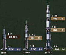
Three variants of the Saturn family which were developed: Saturn I, Saturn IB, and Saturn V

The Saturn family of American rockets was developed by a team of mostly German rocket scientists led by Wernher von Braun to launch heavy payloads to Earth orbit and beyond. The Saturn family used liquid hydrogen as fuel in the upper stages. Originally proposed as a military satellite launcher, they were adopted as the launch vehicles for the Apollo Moon program. Three versions were built and flown: the medium-lift Saturn I, the heavy-lift Saturn IB, and the super heavy-lift Saturn V.

The Saturn name was proposed by von Braun in October 1958 as a logical successor to the Jupiter series as well as the Roman god's powerful position.

In 1963, President John F. Kennedy identified the Saturn I SA-5 launch as being the point where US lift capability would surpass the Soviets, after having been behind since Sputnik. He last mentioned this in a speech given at Brooks AFB in San Antonio on the day before he was assassinated.

To date, the Saturn V is the only launch vehicle to transport human beings beyond low Earth orbit. A total of 24 humans were flown to the Moon in the four years spanning December 1968 through December 1972. No Saturn rocket failed catastrophically in flight.

Summary of variants

All the Saturn family rockets are listed here by date of introduction.

Name Serial number Function Maiden flight Final flight Launches Remarks
Total Success Failure
(+ partial)
Saturn I Block I SA–1–4 Development October 27, 1961 March 28, 1963 4 4 0 Live first stage only
Saturn I Block II SA–5–10 Development January 29, 1964 July 30, 1965 6 6 0 Carried Apollo boilerplate CSM and Pegasus micrometeroid satellites. World's first
Saturn IB SA–200 Apollo spacecraft Earth orbital carrier February 26, 1966 July 15, 1975 9 9 0 Used for Skylab crews and Apollo-Soyuz Test Project
Saturn V SA–500 Apollo spacecraft lunar carrier November 9, 1967 May 14, 1973 13 12 1 Launched nine crewed lunar missions and the Skylab space station

History

Early development

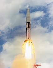
A Saturn I (SA-1) liftoff from LC-34

In the early 1950s, the US Navy and US Army actively developed long-range missiles with the help of German rocket engineers who were involved in developing the successful V-2 during the Second World War. These missiles included the Navy's Viking, and the Army's Corporal, Jupiter and Redstone. Meanwhile, the US Air Force developed its Atlas and Titan missiles, relying more on American engineers.

Infighting among the various branches was constant, with the United States Department of Defense (DoD) deciding which projects to fund for development. On November 26, 1956, Defense Secretary Charles E. Wilson issued a memorandum stripping the Army of offensive missiles with a range of 200 miles (320 km) or greater, and turning their Jupiter missiles over to the Air Force.[4] From that point on, the Air Force would be the primary missile developer, especially for dual-use missiles that could also be used as space launch vehicles.

In late 1956, the Department of Defense released a requirement for a heavy-lift vehicle to orbit a new class of communications and "other" satellites (the spy satellite program was top secret). The requirements, drawn up by the then-unofficial Advanced Research Projects Agency (ARPA), called for a vehicle capable of putting 9,000 to 18,000 kilograms into orbit, or accelerating 2,700 to 5,400 kg to escape velocity.

Since the Wilson memorandum covered only weapons, not space vehicles, the Army Ballistic Missile Agency (ABMA) saw this as a way to continue the development of their own large-rocket projects. In April 1957, von Braun directed Heinz-Hermann Koelle, chief of the Future Projects design branch, to study dedicated launch vehicle designs that could be built as quickly as possible. Koelle evaluated a variety of designs for missile-derived launchers that could place a maximum of about 1,400 kg in orbit, but might be expanded to as much as 4,500 kg with new high-energy upper stages. In any event, these upper stages would not be available until 1961 or 1962 at the earliest, and the launchers would still not meet the DoD requirements for heavy loads.

In order to fill the projected need for loads of 10,000 kg or greater, the ABMA team calculated that a booster (first stage) with a thrust of about 1,500,000 lbf (6,700 kN) thrust would be needed, far greater than any existing or planned missile. For this role they proposed using a number of existing missiles clustered together to produce a single larger booster; using existing designs they looked at combining tankage from one Jupiter as a central core, with eight Redstone diameter tanks attached to it. This relatively cheap configuration allowed existing fabrication and design facilities to be used to produce this "quick and dirty" design.

Two approaches to building the Super-Jupiter were considered; the first used multiple engines to reach the 1,500,000 lbf (6,700 kN) mark, the second used a single much larger engine. Both approaches had their own advantages and disadvantages. Building a smaller engine for clustered use would be a relatively low-risk path from existing systems, but required duplication of systems and made the possibility of a stage failure much higher (adding engines generally reduces reliability, as per Lusser's law). A single larger engine would be more reliable, and would offer higher performance because it eliminated duplication of "dead weight" like propellant plumbing and hydraulics for steering the engines. On the downside, an engine of this size had never been built before and development would be expensive and risky. The Air Force had recently expressed an interest in such an engine, which would develop into the famed F-1, but at the time they were aiming for 1,000,000 lbf (4,400 kN) and the engines would not be ready until the mid-1960s. The engine-cluster appeared to be the only way to meet the requirements on time and budget.

Super-Jupiter was the first-stage booster only; to place payloads in orbit, additional upper stages would be needed. ABMA proposed using either the Titan or Atlas as a second stage, optionally with the new Centaur upper-stage. The Centaur had been proposed by General Dynamics (Astronautics Corp.) as an upper stage for the Atlas (also their design) in order to quickly produce a launcher capable of placing loads up to 8,500 lb (3,900 kg) into low Earth orbit. The Centaur was based on the same "balloon tank" concept as the Atlas, and built on the same jigs at the same 120-inch (3,000 mm) diameter. As the Titan was deliberately built at the same size as well, this meant the Centaur could be used with either missile Given that the Atlas was the higher priority of the two ICBM projects and its production was fully accounted for, ABMA focused on "backup" design, Titan, although they proposed extending it in length in order to carry additional fuel.

In December 1957, ABMA delivered Proposal: A National Integrated Missile and Space Vehicle Development Program to the DoD, detailing their clustered approach. They proposed a booster consisting of a Jupiter missile airframe surrounded by eight Redstones acting as tankage, a thrust plate at the bottom, and four Rocketdyne E-1 engines, each having 380,000 lbf (1,700 kN) of thrust. The ABMA team also left the design open to future expansion with a single 1,500,000 lbf (6,700 kN) engine, which would require relatively minor changes to the design. The upper stage was the lengthened Titan, with the Centaur on top. The result was a very tall and skinny rocket, quite different from the Saturn that eventually emerged.

Specific uses were forecast for each of the military services, including navigation satellites for the Navy; reconnaissance, communications, and meteorological satellites for the Army and Air Force; support for Air Force crewed missions; and surface-to-surface logistics supply for the Army at distances up to 6400 km. Development and testing of the lower stage stack were projected to be completed by 1963, about the same time that the Centaur should become available for testing in combination. The total development cost of $850 million during the years 1958-1963 covered 30 research and development flights.

Sputnik stuns the world

While the Super-Juno program was being drawn up, preparations were underway for the first satellite launch as the US contribution to the International Geophysical Year in 1957. For complex political reasons, the program had been given to the US Navy under Project Vanguard. The Vanguard launcher consisted of a Viking lower stage combined with new uppers adapted from sounding rockets. ABMA provided valuable support on Viking and Vanguard, both with their first-hand knowledge of the V-2, as well as developing its guidance system. The first three Vanguard suborbital test flights had gone off without a hitch, starting in December 1956, and a launch was planned for late 1957.

On October 4, 1957, the Soviet Union unexpectedly launched Sputnik I. Although there had been some idea that the Soviets were working towards this goal, even in public, no one considered it to be very serious. When asked about the possibility in a November 1954 press conference, Defense Secretary Wilson replied: "I wouldn't care if they did." The public did not see it the same way, however, and the event was a major public relations disaster for the US. Vanguard was planned to launch shortly after Sputnik, but a series of delays pushed this into December, when the rocket exploded in spectacular fashion. The press was harsh, referring to the project as "Kaputnik" or "Project Rearguard". As Time magazine noted at the time:

But in the midst of the cold war, Vanguard's cool scientific goal proved to be disastrously modest: the Russians got there first. The post-Sputnik White House explanation that the U.S. was not in a satellite "race" with Russia was not just an after-the-fact alibi. Said Dr. Hagen ten months ago: "We are not attempting in any way to race with the Russians". But in the eyes of the world, the U.S. was in a satellite race whether it wanted to be or not, and because of the Administration's costly failure of imagination, Project Vanguard shuffled along when it should have been running. It was still shuffling when Sputnik's beeps told the world that Russia's satellite program, not the U.S.'s, was the vanguard.

Von Braun responded to Sputnik I's launch by claiming he could have a satellite in orbit within 90 days of being given a go-ahead. His plan was to combine the existing Jupiter C rocket (confusingly, a Redstone adaptation, not a Jupiter) with the solid-fuel engines from the Vanguard, producing the Juno I. There was no immediate response while everyone waited for Vanguard to launch, but the continued delays in Vanguard and the November launch of Sputnik II resulted in the go-ahead being given that month. Von Braun kept his promise with the successful launch of Explorer I on 1 February 1958. Vanguard was finally successful on March 17, 1958.

ARPA selects Juno

Concerned that the Soviets continued to surprise the U.S. with technologies that seemed beyond their capabilities, the DoD studied the problem and concluded that it was primarily bureaucratic. As all of the branches of the military had their own research and development programs, there was considerable duplication and inter-service fighting for resources. Making matters worse, the DoD imposed its own Byzantine procurement and contracting rules, adding considerable overhead. To address these concerns, the DoD initiated the formation of a new research and development group focused on launch vehicles and given wide discretionary powers that cut across traditional Army/Navy/Air Force lines. The group was given the job of catching up to the Soviets in space technology as quickly as possible, using whatever technology it could, regardless of the origin. Formalized as Advanced Research Projects Agency (ARPA) on February 7, 1958, the group examined the DoD launcher requirements and compared the various approaches that were currently available.

At the same time that ABMA was drawing up the Super-Juno proposal, the Air Force was in the midst of working on their Titan C concept. The Air Force had gained valuable experience working with liquid hydrogen on the Lockheed CL-400 Suntan spy plane project and felt confident in their ability to use this volatile fuel for rockets. They had already accepted Krafft Ehricke's arguments that hydrogen was the only practical fuel for upper stages, and started the Centaur project based on the strength of these arguments. Titan C was a hydrogen-burning intermediate stage that would normally sit between the Titan lower and Centaur upper, or could be used without the Centaur for low-Earth orbit missiles like Dyna-Soar. However, as hydrogen is much less dense than "traditional" fuels then in use, especially kerosene, the upper stage would have to be fairly large in order to hold enough fuel. As the Atlas and Titan were both built at 120" diameters it would make sense to build Titan C at this diameter as well, but this would result in an unwieldy tall and skinny rocket with dubious strength and stability. Instead, Titan C proposed building the new stage at a larger 160" diameter, meaning it would be an entirely new rocket.

In comparison, the Super-Juno design was based on off-the-shelf components, with the exception of the E-1 engines. Although it too relied on the Centaur for high-altitude missions, the rocket was usable for low-Earth orbit without Centaur, which offered some flexibility in case Centaur ran into problems. ARPA agreed that the Juno proposal was more likely to meet the timeframes required, although they felt that there was no strong reason to use the E-1, and recommended a lower-risk approach here as well. ABMA responded with a new design, the Juno V (as a continuation of the Juno I and Juno II series of rockets, while Juno III and IV were unbuilt Atlas- and Titan-derived concepts), which replaced the four E-1 engines with eight H-1s, a much more modest upgrade of the existing S-3D already used on the Thor and Jupiter missiles, raising thrust from 150,000 to 188,000 lbf (670 to 840 kN). It was estimated that this approach would save as much as $60 million in development and cut as much as two years of R&D time.

Happy with the results of the redesign, on August 15, 1958, ARPA issued Order Number 14-59 that called on ABMA to:

Initiate a development program to provide a large space vehicle booster of approximately 1 500 000-lb. thrust based on a cluster of available rocket engines. The immediate goal of this program is to demonstrate a full-scale captive dynamic firing by the end of CY 1959.

This was followed on September 11, 1958, with another contract with Rocketdyne to start work on the H-1. On September 23, 1958, ARPA and the Army Ordnance Missile Command (AOMC) drew up an additional agreement enlarging the scope of the program, stating "In addition to the captive dynamic firing..., it is hereby agreed that this program should now be extended to provide for a propulsion flight test of this booster by approximately September 1960". Further, they wanted ABMA to produce three additional boosters, the last two of which would be "capable of placing limited payloads in orbit."

By this point, many in the ABMA group were already referring to the design as Saturn, as von Braun explained it as a reference to the planet after Jupiter. The name change became official in February 1959.

NASA involvement

In addition to ARPA, various groups within the US government had been considering the formation of a civilian agency to handle space exploration. After the Sputnik launch, these efforts gained urgency and were quickly moved forward. NASA was formed on July 29, 1958, and immediately set about studying the problem of crewed space flight, and the launchers needed to work in this field. One goal, even in this early stage, was a crewed lunar mission. At the time, the NASA panels felt that the direct ascent mission profile was the best approach; this placed a single very large spacecraft in orbit, which was capable of flying to the Moon, landing and returning to Earth. To launch such a large spacecraft, a new booster with much greater power would be needed; even the Saturn was not nearly large enough. NASA started examining a number of potential rocket designs under their Nova program.

NASA was not alone in studying crewed lunar missions. Von Braun had always expressed an interest in this goal, and had been studying what would be required for a lunar mission for some time. ABMA's Project Horizon proposed using fifteen Saturn launches to carry up spacecraft components and fuel that would be assembled in orbit to build a single very large lunar craft. This Earth orbit rendezvous mission profile required the least amount of booster capacity per launch, and was thus able to be carried out using the existing rocket design. This would be the first step towards a small crewed base on the moon, which would require several additional Saturn launches every month to supply it.

The Air Force had also started their Lunex Project in 1958, also with a goal of building a crewed lunar outpost. Like NASA, Lunex favored the direct ascent mode, and therefore required much larger boosters. As part of the project, they designed an entirely new rocket series known as the Space Launcher System, or SLS (not to be confused with the Space Launch System part of the Artemis program), which combined a number of solid-fuel boosters with either the Titan missile or a new custom booster stage to address a wide variety of launch weights. The smallest SLS vehicle consisted of a Titan and two strap-on solids, giving it performance similar to Titan C, allowing it to act as a launcher for Dyna-Soar. The largest used much larger solid-rockets and a much-enlarged booster for their direct ascent mission. Combinations in-between these extremes would be used for other satellite launching duties.

Silverstein Committee

Line drawings showing the evolution of the Saturn I rocket, from the original designs to the flown versions, and the uprated Saturn IB

A government commission, the "Saturn Vehicle Evaluation Committee" (better known as the Silverstein Committee), was assembled to recommend specific directions that NASA could take with the existing Army program. The committee recommended the development of new, hydrogen-burning upper stages for the Saturn, and outlined eight different configurations for heavy-lift boosters ranging from very low-risk solutions making heavy use of existing technology, to designs that relied on hardware that had not been developed yet, including the proposed new upper stage. The configurations were:

  • Saturn A
    • A-1 – Saturn lower stage, Titan second stage, and Centaur third stage (von Braun's original concept).
    • A-2 – Saturn lower stage, proposed clustered Jupiter second stage, and Centaur third stage.
  • Saturn B
    • B-1 – Saturn lower stage, proposed clustered Titan second stage, proposed S-IV third stage and Centaur fourth stage.
  • Saturn C
    • C-1 – Saturn lower stage, proposed S-IV second stage.
    • C-2 – Saturn lower stage, proposed S-II second stage, proposed S-IV third stage.
    • C-3, C-4, and C-5 – all based on different variations of a new lower stage using F-1 engines, variations of proposed S-II second stages, and proposed S-IV third stages.

Contracts for the development of a new hydrogen-burning engine were given to Rocketdyne in 1960 and for the development of the Saturn IV stage to Douglas the same year.

Launch history

1965 graph showing cumulative history and projection of Saturn launches by month (along with Atlas and Titan).
 
Saturn Launch History 
PROGRAM VEHICLE MISSION LAUNCH DATE PAD
Saturn I SA-1 SA-1 Oct 27, 1961 LC-34
Saturn I SA-2 SA-2 Apr 25, 1962 34
Saturn I SA-3 SA-3 Nov 16, 1962 34
Saturn I SA-4 SA-4 Mar 28, 1963 34
Saturn I SA-5 SA-5 Jan 29, 1964 LC-37B
Saturn I SA-6 A-101 May 28, 1964 37B
Saturn I SA-7 A-102 Sep 18, 1964 37B
Saturn I SA-9 A-103 Feb 16, 1965 37B
Saturn I SA-8 A-104 May 25, 1965 37B
Saturn I SA-10 A-105 Jul 30, 1965 37B
Saturn IB SA-201 AS-201 Feb 26, 1966 34
Saturn IB SA-203 AS-203 Jul 5, 1966 37B
Saturn IB SA-202 AS-202 Aug 25, 1966 34
Saturn V SA-501 Apollo 4 Nov 9, 1967 LC-39A
Saturn IB SA-204 Apollo 5 Jan 22, 1968 37B
Saturn V SA-502 Apollo 6 Apr 4, 1968 39A
Saturn IB SA-205 Apollo 7 Oct 11, 1968 34
Saturn V SA-503 Apollo 8 Dec 21, 1968 39A
Saturn V SA-504 Apollo 9 Mar 3, 1969 39A
Saturn V SA-505 Apollo 10 May 18, 1969 LC-39B
Saturn V SA-506 Apollo 11 Jul 16, 1969 39A
Saturn V SA-507 Apollo 12 Nov 14, 1969 39A
Saturn V SA-508 Apollo 13 Apr 11, 1970 39A
Saturn V SA-509 Apollo 14 Jan 31, 1971 39A
Saturn V SA-510 Apollo 15 Jul 26, 1971 39A
Saturn V SA-511 Apollo 16 Apr 16, 1972 39A
Saturn V SA-512 Apollo 17 Dec 7, 1972 39A
Saturn V SA-513 Skylab 1 May 14, 1973 39A
Saturn IB SA-206 Skylab 2 May 25, 1973 39B
Saturn IB SA-207 Skylab 3 Jul 28, 1973 39B
Saturn IB SA-208 Skylab 4 Nov 16, 1973 39B
Saturn IB SA-210 ASTP Jul 15, 1975 39B

Apollo program

A Saturn IB (AS-202) liftoff from LC-34
 
von Braun with the F-1 engines of the Saturn V first stage at the U.S. Space and Rocket Center
 
Rollout of Apollo 11's Saturn V on launch pad

The challenge that President John F. Kennedy put to NASA in May 1961 to put an astronaut on the Moon by the end of the decade put a sudden new urgency on the Saturn program. That year saw a flurry of activity as different means of reaching the Moon were evaluated.

Both the Nova and Saturn rockets, which shared a similar design and could share some parts, were evaluated for the mission. However, it was judged that the Saturn would be easier to get into production, since many of the components were designed to be air-transportable. Nova would require new factories for all the major stages, and there were serious concerns that they could not be completed in time. Saturn required only one new factory, for the largest of the proposed lower stages, and was selected primarily for that reason.

The Saturn C-5 (later given the name Saturn V), the most powerful of the Silverstein Committee's configurations, was selected as the most suitable design. At the time the mission mode had not been selected, so they chose the most powerful booster design in order to ensure that there would be ample power. Selection of the lunar orbit rendezvous method reduced the launch weight requirements below those of the Nova, into the C-5's range.

At this point, however, all three stages existed only on paper, and it was realized that it was very likely that the actual lunar spacecraft would be developed and ready for testing long before the booster. NASA, therefore, decided to also continue development of the C-1 (later Saturn I) as a test vehicle, since its lower stage was based on existing technology (Redstone and Jupiter tankage) and its upper stage was already in development. This would provide valuable testing for the S-IV as well as a launch platform for capsules and other components in low earth orbit.

The members of the Saturn family that were actually built were:

  • Saturn I – ten rockets flew: five development flights, and five launches of boilerplate Apollo spacecraft and Pegasus micrometeoroid satellites.
  • Saturn IB – nine launches; a refined version of the Saturn I with a more powerful first stage (designated the S-IB) and using the Saturn V's S-IVB as a second stage. These carried the first Apollo flight crew, plus three Skylab and one Apollo-Soyuz crews, into Earth orbit.
  • Saturn V – 13 launches; the Moon rocket that sent Apollo astronauts to the Moon, and carried the Skylab space station into orbit.

Monday, May 3, 2021

Methane clathrate

From Wikipedia, the free encyclopedia
 
"Burning ice". Methane, released by heating, burns; water drips.
Inset: clathrate structure (University of Göttingen, GZG. Abt. Kristallographie).
Source: United States Geological Survey.

Methane clathrate (CH4·5.75H2O) or (4CH4·23H2O), also called methane hydrate, hydromethane, methane ice, fire ice, natural gas hydrate, or gas hydrate, is a solid clathrate compound (more specifically, a clathrate hydrate) in which a large amount of methane is trapped within a crystal structure of water, forming a solid similar to ice. Originally thought to occur only in the outer regions of the Solar System, where temperatures are low and water ice is common, significant deposits of methane clathrate have been found under sediments on the ocean floors of the Earth. Methane hydrate is formed when hydrogen-bonded water and methane gas come into contact at high pressures and low temperatures in oceans.

Methane clathrates are common constituents of the shallow marine geosphere and they occur in deep sedimentary structures and form outcrops on the ocean floor. Methane hydrates are believed to form by the precipitation or crystallisation of methane migrating from deep along geological faults. Precipitation occurs when the methane comes in contact with water within the sea bed subject to temperature and pressure. In 2008, research on Antarctic Vostok Station and EPICA Dome C ice cores revealed that methane clathrates were also present in deep Antarctic ice cores and record a history of atmospheric methane concentrations, dating to 800,000 years ago. The ice-core methane clathrate record is a primary source of data for global warming research, along with oxygen and carbon dioxide.

General

Methane hydrates were discovered in Russia in the 1960s, and studies for extracting gas from it emerged at the beginning of the 21st century.

Structure and composition

microscope image

The nominal methane clathrate hydrate composition is (CH4)4(H2O)23, or 1 mole of methane for every 5.75 moles of water, corresponding to 13.4% methane by mass, although the actual composition is dependent on how many methane molecules fit into the various cage structures of the water lattice. The observed density is around 0.9 g/cm3, which means that methane hydrate will float to the surface of the sea or of a lake unless it is bound in place by being formed in or anchored to sediment. One litre of fully saturated methane clathrate solid would therefore contain about 120 grams of methane (or around 169 litres of methane gas at 0 °C and 1 atm), or one cubic metre of methane clathrate releases about 160 cubic metres of gas.

Methane forms a "structure-I" hydrate with two dodecahedral (12 vertices, thus 12 water molecules) and six tetradecahedral (14 water molecules) water cages per unit cell. (Because of sharing of water molecules between cages, there are only 46 water molecules per unit cell.) This compares with a hydration number of 20 for methane in aqueous solution. A methane clathrate MAS NMR spectrum recorded at 275 K and 3.1 MPa shows a peak for each cage type and a separate peak for gas phase methane. In 2003, a clay-methane hydrate intercalate was synthesized in which a methane hydrate complex was introduced at the interlayer of a sodium-rich montmorillonite clay. The upper temperature stability of this phase is similar to that of structure-I hydrate.

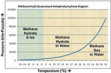
Methane hydrate phase diagram. The horizontal axis shows temperature from -15 to 33 Celsius, the vertical axis shows pressure from 0 to 120,000 kilopascals (0 to 1,184 atmospheres). Hydrate forms above the line. For example, at 4 Celsius hydrate forms above a pressure of about 50 atm/5000 kPa, found at about 500m sea depth.

Natural deposits

Worldwide distribution of confirmed or inferred offshore gas hydrate-bearing sediments, 1996.
Source: USGS
 
Gas hydrate-bearing sediment, from the subduction zone off Oregon
 
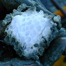
Specific structure of a gas hydrate piece, from the subduction zone off Oregon

Methane clathrates are restricted to the shallow lithosphere (i.e. < 2,000 m depth). Furthermore, necessary conditions are found only in either continental sedimentary rocks in polar regions where average surface temperatures are less than 0 °C; or in oceanic sediment at water depths greater than 300 m where the bottom water temperature is around 2 °C. In addition, deep fresh water lakes may host gas hydrates as well, e.g. the fresh water Lake Baikal, Siberia. Continental deposits have been located in Siberia and Alaska in sandstone and siltstone beds at less than 800 m depth. Oceanic deposits seem to be widespread in the continental shelf (see Fig.) and can occur within the sediments at depth or close to the sediment-water interface. They may cap even larger deposits of gaseous methane.

Oceanic

There are two distinct types of oceanic deposit. The most common is dominated (> 99%) by methane contained in a structure I clathrate and generally found at depth in the sediment. Here, the methane is isotopically light (δ13C < −60‰), which indicates that it is derived from the microbial reduction of CO2. The clathrates in these deep deposits are thought to have formed in situ from the microbially produced methane, since the δ13C values of clathrate and surrounding dissolved methane are similar. However, it is also thought that fresh water used in the pressurization of oil and gas wells in permafrost and along the continental shelves worldwide combines with natural methane to form clathrate at depth and pressure, since methane hydrates are more stable in fresh water than in salt water. Local variations may be very common, since the act of forming hydrate, which extracts pure water from saline formation waters, can often lead to local, and potentially significant, increases in formation water salinity. Hydrates normally exclude the salt in the pore fluid from which it forms, thus they exhibit high electric resistivity just like ice, and sediments containing hydrates have a higher resistivity compared to sediments without gas hydrates (Judge [67]).

These deposits are located within a mid-depth zone around 300–500 m thick in the sediments (the gas hydrate stability zone, or GHSZ) where they coexist with methane dissolved in the fresh, not salt, pore-waters. Above this zone methane is only present in its dissolved form at concentrations that decrease towards the sediment surface. Below it, methane is gaseous. At Blake Ridge on the Atlantic continental rise, the GHSZ started at 190 m depth and continued to 450 m, where it reached equilibrium with the gaseous phase. Measurements indicated that methane occupied 0-9% by volume in the GHSZ, and ~12% in the gaseous zone.

In the less common second type found near the sediment surface some samples have a higher proportion of longer-chain hydrocarbons (< 99% methane) contained in a structure II clathrate. Carbon from this type of clathrate is isotopically heavier (δ13C is −29 to −57 ‰) and is thought to have migrated upwards from deep sediments, where methane was formed by thermal decomposition of organic matter. Examples of this type of deposit have been found in the Gulf of Mexico and the Caspian Sea.

Some deposits have characteristics intermediate between the microbially and thermally sourced types and are considered to be formed from a mixture of the two.

The methane in gas hydrates is dominantly generated by microbial consortia degrading organic matter in low oxygen environments, with the methane itself produced by methanogenic archaea. Organic matter in the uppermost few centimetres of sediments is first attacked by aerobic bacteria, generating CO2, which escapes from the sediments into the water column. Below this region of aerobic activity, anaerobic processes take over, including, successively with depth, the microbial reduction of nitrite/nitrate, metal oxides, and then sulfates are reduced to sulfides. Finally, once sulfate is used up, methanogenesis becomes a dominant pathway for organic carbon remineralization.

If the sedimentation rate is low (about 1 cm/yr), the organic carbon content is low (about 1% ), and oxygen is abundant, aerobic bacteria can use up all the organic matter in the sediments faster than oxygen is depleted, so lower-energy electron acceptors are not used. But where sedimentation rates and the organic carbon content are high, which is typically the case on continental shelves and beneath western boundary current upwelling zones, the pore water in the sediments becomes anoxic at depths of only a few centimeters or less. In such organic-rich marine sediments, sulfate then becomes the most important terminal electron acceptor due to its high concentration in seawater, although it too is depleted by a depth of centimeters to meters. Below this, methane is produced. This production of methane is a rather complicated process, requiring a highly reducing environment (Eh −350 to −450 mV) and a pH between 6 and 8, as well as a complex syntrophic consortia of different varieties of archaea and bacteria, although it is only archaea that actually emit methane.

In some regions (e.g., Gulf of Mexico, Joetsu Basin) methane in clathrates may be at least partially derive from thermal degradation of organic matter (e.g. petroleum generation), with oil even forming an exotic component within the hydrate itself that can be recovered when the hydrate is disassociated. The methane in clathrates typically has a biogenic isotopic signature and highly variable δ13C (−40 to −100‰), with an approximate average of about −65‰ . Below the zone of solid clathrates, large volumes of methane may form bubbles of free gas in the sediments.

The presence of clathrates at a given site can often be determined by observation of a "bottom simulating reflector" (BSR), which is a seismic reflection at the sediment to clathrate stability zone interface caused by the unequal densities of normal sediments and those laced with clathrates.

Gas hydrate pingos have been discovered in the Arctic oceans Barents sea. Methane is bubbling from these dome like structures, with some of these gas flares extending close to the sea surface.

Reservoir size

Gas hydrate under carbonate rock.jpg


The size of the oceanic methane clathrate reservoir is poorly known, and estimates of its size decreased by roughly an order of magnitude per decade since it was first recognized that clathrates could exist in the oceans during the 1960s and 1970s. The highest estimates (e.g. 3×10¹⁸ m3) were based on the assumption that fully dense clathrates could litter the entire floor of the deep ocean. Improvements in our understanding of clathrate chemistry and sedimentology have revealed that hydrates form in only a narrow range of depths (continental shelves), at only some locations in the range of depths where they could occur (10-30% of the Gas hydrate stability zone), and typically are found at low concentrations (0.9–1.5% by volume) at sites where they do occur. Recent estimates constrained by direct sampling suggest the global inventory occupies between 1×10¹⁵ and 5×10¹⁵ cubic metres (0.24 and 1.2 million cubic miles). This estimate, corresponding to 500–2500 gigatonnes carbon (Gt C), is smaller than the 5000 Gt C estimated for all other geo-organic fuel reserves but substantially larger than the ~230 Gt C estimated for other natural gas sources. The permafrost reservoir has been estimated at about 400 Gt C in the Arctic, but no estimates have been made of possible Antarctic reservoirs. These are large amounts. In comparison, the total carbon in the atmosphere is around 800 gigatons.

These modern estimates are notably smaller than the 10,000 to 11,000 Gt C (2×10¹⁶ m3) proposed by previous researchers as a reason to consider clathrates to be a geo-organic fuel resource (MacDonald 1990, Kvenvolden 1998). Lower abundances of clathrates do not rule out their economic potential, but a lower total volume and apparently low concentration at most sites does suggest that only a limited percentage of clathrates deposits may provide an economically viable resource.

Continental

Methane clathrates in continental rocks are trapped in beds of sandstone or siltstone at depths of less than 800 m. Sampling indicates they are formed from a mix of thermally and microbially derived gas from which the heavier hydrocarbons were later selectively removed. These occur in Alaska, Siberia, and Northern Canada.

In 2008, Canadian and Japanese researchers extracted a constant stream of natural gas from a test project at the Mallik gas hydrate site in the Mackenzie River delta. This was the second such drilling at Mallik: the first took place in 2002 and used heat to release methane. In the 2008 experiment, researchers were able to extract gas by lowering the pressure, without heating, requiring significantly less energy. The Mallik gas hydrate field was first discovered by Imperial Oil in 1971–1972.

Commercial use

Economic deposits of hydrate are termed natural gas hydrate (NGH) and store 164 m3 of methane, 0.8 m3 water in 1 m3 hydrate. Most NGH is found beneath the seafloor (95%) where it exists in thermodynamic equilibrium. The sedimentary methane hydrate reservoir probably contains 2–10 times the currently known reserves of conventional natural gas, as of 2013. This represents a potentially important future source of hydrocarbon fuel. However, in the majority of sites deposits are thought to be too dispersed for economic extraction. Other problems facing commercial exploitation are detection of viable reserves and development of the technology for extracting methane gas from the hydrate deposits.

In August 2006, China announced plans to spend 800 million yuan (US$100 million) over the next 10 years to study natural gas hydrates. A potentially economic reserve in the Gulf of Mexico may contain approximately 100 billion cubic metres (3.5×10¹² cu ft) of gas. Bjørn Kvamme and Arne Graue at the Institute for Physics and technology at the University of Bergen have developed a method for injecting CO
2
into hydrates and reversing the process; thereby extracting CH4 by direct exchange. The University of Bergen's method is being field tested by ConocoPhillips and state-owned Japan Oil, Gas and Metals National Corporation (JOGMEC), and partially funded by the U.S. Department of Energy. The project has already reached injection phase and was analyzing resulting data by March 12, 2012.

On March 12, 2013, JOGMEC researchers announced that they had successfully extracted natural gas from frozen methane hydrate. In order to extract the gas, specialized equipment was used to drill into and depressurize the hydrate deposits, causing the methane to separate from the ice. The gas was then collected and piped to surface where it was ignited to prove its presence. According to an industry spokesperson, "It [was] the world's first offshore experiment producing gas from methane hydrate". Previously, gas had been extracted from onshore deposits, but never from offshore deposits which are much more common. The hydrate field from which the gas was extracted is located 50 kilometres (31 mi) from central Japan in the Nankai Trough, 300 metres (980 ft) under the sea. A spokesperson for JOGMEC remarked "Japan could finally have an energy source to call its own". Marine geologist Mikio Satoh remarked "Now we know that extraction is possible. The next step is to see how far Japan can get costs down to make the technology economically viable." Japan estimates that there are at least 1.1 trillion cubic meters of methane trapped in the Nankai Trough, enough to meet the country's needs for more than ten years.

Both Japan and China announced in May 2017 a breakthrough for mining methane clathrates, when they extracted methane from hydrates in the South China Sea. China described the result as a breakthrough; Praveen Linga from the Department of Chemical and Biomolecular Engineering at the National University of Singapore agreed "Compared with the results we have seen from Japanese research, the Chinese scientists have managed to extract much more gas in their efforts". Industry consensus is that commercial-scale production remains years away.

Environmental concerns

Experts caution that environmental impacts are still being investigated and that methane—a greenhouse gas with around 25 times as much global warming potential over a 100-year period (GWP100) as carbon dioxide—could potentially escape into the atmosphere if something goes wrong. Furthermore, while cleaner than coal, burning natural gas also creates carbon emissions.

Hydrates in natural gas processing

Routine operations

Methane clathrates (hydrates) are also commonly formed during natural gas production operations, when liquid water is condensed in the presence of methane at high pressure. It is known that larger hydrocarbon molecules like ethane and propane can also form hydrates, although longer molecules (butanes, pentanes) cannot fit into the water cage structure and tend to destabilise the formation of hydrates.

Once formed, hydrates can block pipeline and processing equipment. They are generally then removed by reducing the pressure, heating them, or dissolving them by chemical means (methanol is commonly used). Care must be taken to ensure that the removal of the hydrates is carefully controlled, because of the potential for the hydrate to undergo a phase transition from the solid hydrate to release water and gaseous methane at a high rate when the pressure is reduced. The rapid release of methane gas in a closed system can result in a rapid increase in pressure.

It is generally preferable to prevent hydrates from forming or blocking equipment. This is commonly achieved by removing water, or by the addition of ethylene glycol (MEG) or methanol, which act to depress the temperature at which hydrates will form. In recent years, development of other forms of hydrate inhibitors have been developed, like Kinetic Hydrate Inhibitors (which by far slow the rate of hydrate formation) and anti-agglomerates, which do not prevent hydrates forming, but do prevent them sticking together to block equipment.

Effect of hydrate phase transition during deep water drilling

When drilling in oil- and gas-bearing formations submerged in deep water, the reservoir gas may flow into the well bore and form gas hydrates owing to the low temperatures and high pressures found during deep water drilling. The gas hydrates may then flow upward with drilling mud or other discharged fluids. When the hydrates rise, the pressure in the annulus decreases and the hydrates dissociate into gas and water. The rapid gas expansion ejects fluid from the well, reducing the pressure further, which leads to more hydrate dissociation and further fluid ejection. The resulting violent expulsion of fluid from the annulus is one potential cause or contributor to the "kick". (Kicks, which can cause blowouts, typically do not involve hydrates.

Measures which reduce the risk of hydrate formation include:

  • High flow-rates, which limit the time for hydrate formation in a volume of fluid, thereby reducing the kick potential.
  • Careful measuring of line flow to detect incipient hydrate plugging.
  • Additional care in measuring when gas production rates are low and the possibility of hydrate formation is higher than at relatively high gas flow rates.
  • Monitoring of well casing after it is "shut in" (isolated) may indicate hydrate formation. Following "shut in", the pressure rises while gas diffuses through the reservoir to the bore hole; the rate of pressure rise exhibit a reduced rate of increase while hydrates are forming.
  • Additions of energy (e.g., the energy released by setting cement used in well completion) can raise the temperature and convert hydrates to gas, producing a "kick".

Blowout recovery

Concept diagram of oil containment domes, forming upsidedown funnels in order to pipe oil to surface ships. The sunken oil rig is nearby.

At sufficient depths, methane complexes directly with water to form methane hydrates, as was observed during the Deepwater Horizon oil spill in 2010. BP engineers developed and deployed a subsea oil recovery system over oil spilling from a deepwater oil well 5,000 feet (1,500 m) below sea level to capture escaping oil. This involved placing a 125-tonne (276,000 lb) dome over the largest of the well leaks and piping it to a storage vessel on the surface. This option had the potential to collect some 85% of the leaking oil but was previously untested at such depths. BP deployed the system on May 7–8, but it failed due to buildup of methane clathrate inside the dome; with its low density of approximately 0.9 g/cm3 the methane hydrates accumulated in the dome, adding buoyancy and obstructing flow.

Methane clathrates and climate change

Methane is a powerful greenhouse gas. Despite its short atmospheric half life of 12 years, methane has a global warming potential of 86 over 20 years and 34 over 100 years (IPCC, 2013). The sudden release of large amounts of natural gas from methane clathrate deposits has been hypothesized as a cause of past and possibly future climate changes. Events possibly linked in this way are the Permian-Triassic extinction event and the Paleocene-Eocene Thermal Maximum.

Climate scientists like James E. Hansen predict that methane clathrates in permafrost regions will be released because of global warming, unleashing powerful feedback forces that may cause runaway climate change.

Research carried out in 2008 in the Siberian Arctic found millions of tonnes of methane being released with concentrations in some regions reaching up to 100 times above normal.

While investigating the East Siberian Arctic Ocean during the Summer, researchers were surprised by the high concentration of methane, and theorized that it was being released from pockets of methane clathrates embedded in ice on the sea floor which had been destabilized by warmer water.

In 2014 based on their research on the northern United States Atlantic marine continental margins from Cape Hatteras to Georges Bank, a group of scientists from the US Geological Survey, the Department of Geosciences, Mississippi State University, Department of Geological Sciences, Brown University and Earth Resources Technology, claimed there was widespread leakage of methane.

Scientists from the Center for Arctic Gas Hydrate (CAGE), Environment and Climate at the University of Tromsø, published a study in June 2017, describing over a hundred ocean sediment craters, some 300 meters wide and up to 30 meters deep, formed due to explosive eruptions, attributed to destabilizing methane hydrates, following ice-sheet retreat during the last glacial period, around 15,000 years ago, a few centuries after the Bølling-Allerød warming. These areas around the Barents Sea, still seep methane today, and still existing bulges with methane reservoirs could eventually have the same fate.

Natural gas hydrates for gas storage and transportation

Since methane clathrates are stable at a higher temperature than liquefied natural gas (LNG) (−20 vs −162 °C), there is some interest in converting natural gas into clathrates (Solidified Natural Gas or SNG) rather than liquifying it when transporting it by seagoing vessels. A significant advantage would be that the production of natural gas hydrate (NGH) from natural gas at the terminal would require a smaller refrigeration plant and less energy than LNG would. Offsetting this, for 100 tonnes of methane transported, 750 tonnes of methane hydrate would have to be transported; since this would require a ship of 7.5 times greater displacement, or require more ships, it is unlikely to prove economically feasible.. Recently, methane hydrate has received considerable interest for large scale stationary storage application due to the very mild storage conditions with the inclusion of tetrahydrofuran (THF) as a co-guest. With the inclusion of tetrahydrofuran, though there is a slight reduction in the gas storage capacity, the hydrates have been demonstrated to be stable for several months in a recent study at −2 °C and atmospheric pressure. A recent study has demonstrated that SNG can be formed directly with seawater instead of pure water in combination with THF.


Cretaceous–Paleogene extinction event

From Wikipedia, the free encyclopedia https://en.wikipedia.org/wiki/Cretaceous–Paleogene_extinction_event ...