Search This Blog

Friday, August 19, 2022

Network analysis (electrical circuits)

From Wikipedia, the free encyclopedia
https://en.wikipedia.org/wiki/Network_analysis_(electrical_circuits)

Linear network analysis
Elements

ResistanceCapacitor button.svgInductor button.svgReactanceImpedanceVoltage button.svg
ConductanceElastance button.svgBlank button.svgSusceptance button.svgAdmittance button.svgCurrent button.svg

Components

Resistor button.svg Capacitor button.svg Inductor button.svg Ohm's law button.svg

Series and parallel circuits

Series resistor button.svgParallel resistor button.svgSeries capacitor button.svgParallel capacitor button.svgSeries inductor button.svgParallel inductor button.svg

Impedance transforms

Y-Δ transform Δ-Y transform star-polygon transforms Dual button.svg

Generator theorems Network theorems

Thevenin button.svgNorton button.svgMillman button.svg

KCL button.svgKVL button.svgTellegen button.svg

Network analysis methods

KCL button.svg KVL button.svg Superposition button.svg

Two-port parameters

z-parametersy-parametersh-parametersg-parametersAbcd-parameter button.svgS-parameters


A network, in the context of electrical engineering and electronics, is a collection of interconnected components. Network analysis is the process of finding the voltages across, and the currents through, all network components. There are many techniques for calculating these values. However, for the most part, the techniques assume linear components. Except where stated, the methods described in this article are applicable only to linear network analysis.

Definitions

Component A device with two or more terminals into which, or out of which, current may flow.
Node A point at which terminals of more than two components are joined. A conductor with a substantially zero resistance is considered to be a node for the purpose of analysis.
Branch The component(s) joining two nodes.
Mesh A group of branches within a network joined so as to form a complete loop such that there is no other loop inside it.
Port Two terminals where the current into one is identical to the current out of the other.
Circuit A current from one terminal of a generator, through load component(s) and back into the other terminal. A circuit is, in this sense, a one-port network and is a trivial case to analyse. If there is any connection to any other circuits then a non-trivial network has been formed and at least two ports must exist. Often, "circuit" and "network" are used interchangeably, but many analysts reserve "network" to mean an idealised model consisting of ideal components.
Transfer function The relationship of the currents and/or voltages between two ports. Most often, an input port and an output port are discussed and the transfer function is described as gain or attenuation.
Component transfer function For a two-terminal component (i.e. one-port component), the current and voltage are taken as the input and output and the transfer function will have units of impedance or admittance (it is usually a matter of arbitrary convenience whether voltage or current is considered the input). A three (or more) terminal component effectively has two (or more) ports and the transfer function cannot be expressed as a single impedance. The usual approach is to express the transfer function as a matrix of parameters. These parameters can be impedances, but there is a large number of other approaches (see two-port network).

Equivalent circuits

Circuit equivalence.png

A useful procedure in network analysis is to simplify the network by reducing the number of components. This can be done by replacing physical components with other notional components that have the same effect. A particular technique might directly reduce the number of components, for instance by combining impedances in series. On the other hand, it might merely change the form into one in which the components can be reduced in a later operation. For instance, one might transform a voltage generator into a current generator using Norton's theorem in order to be able to later combine the internal resistance of the generator with a parallel impedance load.

A resistive circuit is a circuit containing only resistors, ideal current sources, and ideal voltage sources. If the sources are constant (DC) sources, the result is a DC circuit. Analysis of a circuit consists of solving for the voltages and currents present in the circuit. The solution principles outlined here also apply to phasor analysis of AC circuits.

Two circuits are said to be equivalent with respect to a pair of terminals if the voltage across the terminals and current through the terminals for one network have the same relationship as the voltage and current at the terminals of the other network.

If implies for all (real) values of , then with respect to terminals ab and xy, circuit 1 and circuit 2 are equivalent.

The above is a sufficient definition for a one-port network. For more than one port, then it must be defined that the currents and voltages between all pairs of corresponding ports must bear the same relationship. For instance, star and delta networks are effectively three port networks and hence require three simultaneous equations to fully specify their equivalence.

Impedances in series and in parallel

Some two terminal network of impedances can eventually be reduced to a single impedance by successive applications of impedances in series or impedances in parallel.

Impedances in series:

Impedances in parallel:

The above simplified for only two impedances in parallel:

Delta-wye transformation

Delta-Star Transformation.svg

A network of impedances with more than two terminals cannot be reduced to a single impedance equivalent circuit. An n-terminal network can, at best, be reduced to n impedances (at worst nC2). For a three terminal network, the three impedances can be expressed as a three node delta (Δ) network or four node star (Y) network. These two networks are equivalent and the transformations between them are given below. A general network with an arbitrary number of nodes cannot be reduced to the minimum number of impedances using only series and parallel combinations. In general, Y-Δ and Δ-Y transformations must also be used. For some networks the extension of Y-Δ to star-polygon transformations may also be required.

For equivalence, the impedances between any pair of terminals must be the same for both networks, resulting in a set of three simultaneous equations. The equations below are expressed as resistances but apply equally to the general case with impedances.

Delta-to-star transformation equations

Star-to-delta transformation equations

General form of network node elimination

The star-to-delta and series-resistor transformations are special cases of the general resistor network node elimination algorithm. Any node connected by resistors ( .. ) to nodes 1 .. N can be replaced by resistors interconnecting the remaining nodes. The resistance between any two nodes and is given by:

For a star-to-delta () this reduces to:

For a series reduction () this reduces to:

For a dangling resistor () it results in the elimination of the resistor because .

Source transformation

Sourcetransform.svg

A generator with an internal impedance (i.e. non-ideal generator) can be represented as either an ideal voltage generator or an ideal current generator plus the impedance. These two forms are equivalent and the transformations are given below. If the two networks are equivalent with respect to terminals ab, then V and I must be identical for both networks. Thus,

or
  • Norton's theorem states that any two-terminal linear network can be reduced to an ideal current generator and a parallel impedance.
  • Thévenin's theorem states that any two-terminal linear network can be reduced to an ideal voltage generator plus a series impedance.

Simple networks

Some very simple networks can be analysed without the need to apply the more systematic approaches.

Voltage division of series components

Consider n impedances that are connected in series. The voltage across any impedance is

Current division of parallel components

Consider n admittances that are connected in parallel. The current through any admittance is

for

Special case: Current division of two parallel components

Nodal analysis

1. Label all nodes in the circuit. Arbitrarily select any node as reference.

2. Define a voltage variable from every remaining node to the reference. These voltage variables must be defined as voltage rises with respect to the reference node.

3. Write a KCL equation for every node except the reference.

4. Solve the resulting system of equations.

Mesh analysis

Mesh — a loop that does not contain an inner loop.

1. Count the number of “window panes” in the circuit. Assign a mesh current to each window pane.

2. Write a KVL equation for every mesh whose current is unknown.

3. Solve the resulting equations

Superposition

In this method, the effect of each generator in turn is calculated. All the generators other than the one being considered are removed and either short-circuited in the case of voltage generators or open-circuited in the case of current generators. The total current through or the total voltage across a particular branch is then calculated by summing all the individual currents or voltages.

There is an underlying assumption to this method that the total current or voltage is a linear superposition of its parts. Therefore, the method cannot be used if non-linear components are present. Superposition of powers cannot be used to find total power consumed by elements even in linear circuits. Power varies according to the square of total voltage or current and the square of the sum is not generally equal to the sum of the squares. Total power in an element can be found by applying superposition to the voltages and current independently and then calculating power from the total voltage and current.

Choice of method

Choice of method is to some extent a matter of taste. If the network is particularly simple or only a specific current or voltage is required then ad-hoc application of some simple equivalent circuits may yield the answer without recourse to the more systematic methods.

  • Nodal analysis: The number of voltage variables, and hence simultaneous equations to solve, equals the number of nodes minus one. Every voltage source connected to the reference node reduces the number of unknowns and equations by one.
  • Mesh analysis: The number of current variables, and hence simultaneous equations to solve, equals the number of meshes. Every current source in a mesh reduces the number of unknowns by one. Mesh analysis can only be used with networks which can be drawn as a planar network, that is, with no crossing components.
  • Superposition is possibly the most conceptually simple method but rapidly leads to a large number of equations and messy impedance combinations as the network becomes larger.
  • Effective medium approximations: For a network consisting of a high density of random resistors, an exact solution for each individual element may be impractical or impossible. Instead, the effective resistance and current distribution properties can be modelled in terms of graph measures and geometrical properties of networks.

Transfer function

A transfer function expresses the relationship between an input and an output of a network. For resistive networks, this will always be a simple real number or an expression which boils down to a real number. Resistive networks are represented by a system of simultaneous algebraic equations. However, in the general case of linear networks, the network is represented by a system of simultaneous linear differential equations. In network analysis, rather than use the differential equations directly, it is usual practice to carry out a Laplace transform on them first and then express the result in terms of the Laplace parameter s, which in general is complex. This is described as working in the s-domain. Working with the equations directly would be described as working in the time (or t) domain because the results would be expressed as time varying quantities. The Laplace transform is the mathematical method of transforming between the s-domain and the t-domain.

This approach is standard in control theory and is useful for determining stability of a system, for instance, in an amplifier with feedback.

Two terminal component transfer functions

For two terminal components the transfer function, or more generally for non-linear elements, the constitutive equation, is the relationship between the current input to the device and the resulting voltage across it. The transfer function, Z(s), will thus have units of impedance – ohms. For the three passive components found in electrical networks, the transfer functions are;

Resistor
Inductor
Capacitor

For a network to which only steady ac signals are applied, s is replaced with and the more familiar values from ac network theory result.

Resistor
Inductor
Capacitor

Finally, for a network to which only steady dc is applied, s is replaced with zero and dc network theory applies.

Resistor
Inductor
Capacitor

Two port network transfer function

Transfer functions, in general, in control theory are given the symbol H(s). Most commonly in electronics, transfer function is defined as the ratio of output voltage to input voltage and given the symbol A(s), or more commonly (because analysis is invariably done in terms of sine wave response), A(jω), so that;

The A standing for attenuation, or amplification, depending on context. In general, this will be a complex function of , which can be derived from an analysis of the impedances in the network and their individual transfer functions. Sometimes the analyst is only interested in the magnitude of the gain and not the phase angle. In this case the complex numbers can be eliminated from the transfer function and it might then be written as;

Two port parameters

The concept of a two-port network can be useful in network analysis as a black box approach to analysis. The behaviour of the two-port network in a larger network can be entirely characterised without necessarily stating anything about the internal structure. However, to do this it is necessary to have more information than just the A(jω) described above. It can be shown that four such parameters are required to fully characterise the two-port network. These could be the forward transfer function, the input impedance, the reverse transfer function (i.e., the voltage appearing at the input when a voltage is applied to the output) and the output impedance. There are many others (see the main article for a full listing), one of these expresses all four parameters as impedances. It is usual to express the four parameters as a matrix;

The matrix may be abbreviated to a representative element;

or just

These concepts are capable of being extended to networks of more than two ports. However, this is rarely done in reality because, in many practical cases, ports are considered either purely input or purely output. If reverse direction transfer functions are ignored, a multi-port network can always be decomposed into a number of two-port networks.

Distributed components

Where a network is composed of discrete components, analysis using two-port networks is a matter of choice, not essential. The network can always alternatively be analysed in terms of its individual component transfer functions. However, if a network contains distributed components, such as in the case of a transmission line, then it is not possible to analyse in terms of individual components since they do not exist. The most common approach to this is to model the line as a two-port network and characterise it using two-port parameters (or something equivalent to them). Another example of this technique is modelling the carriers crossing the base region in a high frequency transistor. The base region has to be modelled as distributed resistance and capacitance rather than lumped components.

Image analysis

Transmission lines and certain types of filter design use the image method to determine their transfer parameters. In this method, the behaviour of an infinitely long cascade connected chain of identical networks is considered. The input and output impedances and the forward and reverse transmission functions are then calculated for this infinitely long chain. Although the theoretical values so obtained can never be exactly realised in practice, in many cases they serve as a very good approximation for the behaviour of a finite chain as long as it is not too short.

Non-linear networks

Most electronic designs are, in reality, non-linear. There are very few that do not include some semiconductor devices. These are invariably non-linear, the transfer function of an ideal semiconductor p-n junction is given by the very non-linear relationship;

where;

  • i and v are the instantaneous current and voltage.
  • Io is an arbitrary parameter called the reverse leakage current whose value depends on the construction of the device.
  • VT is a parameter proportional to temperature called the thermal voltage and equal to about 25mV at room temperature.

There are many other ways that non-linearity can appear in a network. All methods utilising linear superposition will fail when non-linear components are present. There are several options for dealing with non-linearity depending on the type of circuit and the information the analyst wishes to obtain.

Constitutive equations

The diode equation above is an example of an element constitutive equation of the general form,

This can be thought of as a non-linear resistor. The corresponding constitutive equations for non-linear inductors and capacitors are respectively;

where f is any arbitrary function, φ is the stored magnetic flux and q is the stored charge.

Existence, uniqueness and stability

An important consideration in non-linear analysis is the question of uniqueness. For a network composed of linear components there will always be one, and only one, unique solution for a given set of boundary conditions. This is not always the case in non-linear circuits. For instance, a linear resistor with a fixed current applied to it has only one solution for the voltage across it. On the other hand, the non-linear tunnel diode has up to three solutions for the voltage for a given current. That is, a particular solution for the current through the diode is not unique, there may be others, equally valid. In some cases there may not be a solution at all: the question of existence of solutions must be considered.

Another important consideration is the question of stability. A particular solution may exist, but it may not be stable, rapidly departing from that point at the slightest stimulation. It can be shown that a network that is absolutely stable for all conditions must have one, and only one, solution for each set of conditions.

Methods

Boolean analysis of switching networks

A switching device is one where the non-linearity is utilised to produce two opposite states. CMOS devices in digital circuits, for instance, have their output connected to either the positive or the negative supply rail and are never found at anything in between except during a transient period when the device is switching. Here the non-linearity is designed to be extreme, and the analyst can take advantage of that fact. These kinds of networks can be analysed using Boolean algebra by assigning the two states ("on"/"off", "positive"/"negative" or whatever states are being used) to the boolean constants "0" and "1".

The transients are ignored in this analysis, along with any slight discrepancy between the state of the device and the nominal state assigned to a boolean value. For instance, boolean "1" may be assigned to the state of +5V. The output of the device may be +4.5V but the analyst still considers this to be boolean "1". Device manufacturers will usually specify a range of values in their data sheets that are to be considered undefined (i.e. the result will be unpredictable).

The transients are not entirely uninteresting to the analyst. The maximum rate of switching is determined by the speed of transition from one state to the other. Happily for the analyst, for many devices most of the transition occurs in the linear portion of the devices transfer function and linear analysis can be applied to obtain at least an approximate answer.

It is mathematically possible to derive boolean algebras that have more than two states. There is not too much use found for these in electronics, although three-state devices are passingly common.

Separation of bias and signal analyses

This technique is used where the operation of the circuit is to be essentially linear, but the devices used to implement it are non-linear. A transistor amplifier is an example of this kind of network. The essence of this technique is to separate the analysis into two parts. Firstly, the dc biases are analysed using some non-linear method. This establishes the quiescent operating point of the circuit. Secondly, the small signal characteristics of the circuit are analysed using linear network analysis. Examples of methods that can be used for both these stages are given below.

Graphical method of dc analysis

In a great many circuit designs, the dc bias is fed to a non-linear component via a resistor (or possibly a network of resistors). Since resistors are linear components, it is particularly easy to determine the quiescent operating point of the non-linear device from a graph of its transfer function. The method is as follows: from linear network analysis the output transfer function (that is output voltage against output current) is calculated for the network of resistor(s) and the generator driving them. This will be a straight line (called the load line) and can readily be superimposed on the transfer function plot of the non-linear device. The point where the lines cross is the quiescent operating point.

Perhaps the easiest practical method is to calculate the (linear) network open circuit voltage and short circuit current and plot these on the transfer function of the non-linear device. The straight line joining these two point is the transfer function of the network.

In reality, the designer of the circuit would proceed in the reverse direction to that described. Starting from a plot provided in the manufacturers data sheet for the non-linear device, the designer would choose the desired operating point and then calculate the linear component values required to achieve it.

It is still possible to use this method if the device being biased has its bias fed through another device which is itself non-linear – a diode for instance. In this case however, the plot of the network transfer function onto the device being biased would no longer be a straight line and is consequently more tedious to do.

Small signal equivalent circuit

This method can be used where the deviation of the input and output signals in a network stay within a substantially linear portion of the non-linear devices transfer function, or else are so small that the curve of the transfer function can be considered linear. Under a set of these specific conditions, the non-linear device can be represented by an equivalent linear network. It must be remembered that this equivalent circuit is entirely notional and only valid for the small signal deviations. It is entirely inapplicable to the dc biasing of the device.

For a simple two-terminal device, the small signal equivalent circuit may be no more than two components. A resistance equal to the slope of the v/i curve at the operating point (called the dynamic resistance), and tangent to the curve. A generator, because this tangent will not, in general, pass through the origin. With more terminals, more complicated equivalent circuits are required.

A popular form of specifying the small signal equivalent circuit amongst transistor manufacturers is to use the two-port network parameters known as [h] parameters. These are a matrix of four parameters as with the [z] parameters but in the case of the [h] parameters they are a hybrid mixture of impedances, admittances, current gains and voltage gains. In this model the three terminal transistor is considered to be a two port network, one of its terminals being common to both ports. The [h] parameters are quite different depending on which terminal is chosen as the common one. The most important parameter for transistors is usually the forward current gain, h21, in the common emitter configuration. This is designated hfe on data sheets.

The small signal equivalent circuit in terms of two-port parameters leads to the concept of dependent generators. That is, the value of a voltage or current generator depends linearly on a voltage or current elsewhere in the circuit. For instance the [z] parameter model leads to dependent voltage generators as shown in this diagram;

[z] parameter equivalent circuit showing dependent voltage generators

There will always be dependent generators in a two-port parameter equivalent circuit. This applies to the [h] parameters as well as to the [z] and any other kind. These dependencies must be preserved when developing the equations in a larger linear network analysis.

Piecewise linear method

In this method, the transfer function of the non-linear device is broken up into regions. Each of these regions is approximated by a straight line. Thus, the transfer function will be linear up to a particular point where there will be a discontinuity. Past this point the transfer function will again be linear but with a different slope.

A well known application of this method is the approximation of the transfer function of a pn junction diode. The transfer function of an ideal diode has been given at the top of this (non-linear) section. However, this formula is rarely used in network analysis, a piecewise approximation being used instead. It can be seen that the diode current rapidly diminishes to -Io as the voltage falls. This current, for most purposes, is so small it can be ignored. With increasing voltage, the current increases exponentially. The diode is modelled as an open circuit up to the knee of the exponential curve, then past this point as a resistor equal to the bulk resistance of the semiconducting material.

The commonly accepted values for the transition point voltage are 0.7V for silicon devices and 0.3V for germanium devices. An even simpler model of the diode, sometimes used in switching applications, is short circuit for forward voltages and open circuit for reverse voltages.

The model of a forward biased pn junction having an approximately constant 0.7V is also a much used approximation for transistor base-emitter junction voltage in amplifier design.

The piecewise method is similar to the small signal method in that linear network analysis techniques can only be applied if the signal stays within certain bounds. If the signal crosses a discontinuity point then the model is no longer valid for linear analysis purposes. The model does have the advantage over small signal however, in that it is equally applicable to signal and dc bias. These can therefore both be analysed in the same operations and will be linearly superimposable.

Time-varying components

In linear analysis, the components of the network are assumed to be unchanging, but in some circuits this does not apply, such as sweep oscillators, voltage controlled amplifiers, and variable equalisers. In many circumstances the change in component value is periodic. A non-linear component excited with a periodic signal, for instance, can be represented as a periodically varying linear component. Sidney Darlington disclosed a method of analysing such periodic time varying circuits. He developed canonical circuit forms which are analogous to the canonical forms of Ronald M. Foster and Wilhelm Cauer used for analysing linear circuits.

Vector circuit theory

Generalization of circuit theory based on scalar quantities to vectorial currents is a necessity for newly evolving circuits such as spin circuits. Generalized circuit variables consist of four components: scalar current and vector spin current in x, y, and z directions. The voltages and currents each become vector quantities with conductance described as a 4x4 spin conductance matrix.

Electrical engineering

From Wikipedia, the free encyclopedia
 
Electrical engineering
Umspannwerk-Pulverdingen 380kV-Trennschalter.jpg
NamesElectrical engineer
Activity sectors
Electronics, electrical circuits, electromagnetics, power engineering, electrical machines, telecommunication, control systems, signal processing, optics, photonics
Description
CompetenciesTechnical knowledge, management skills, design (see also Glossary of electrical and electronics engineering)
Fields of
employment
Technology, science, exploration, military, industry

Electrical engineering is an engineering discipline concerned with the study, design, and application of equipment, devices, and systems which use electricity, electronics, and electromagnetism. It emerged as an identifiable occupation in the latter half of the 19th century after commercialization of the electric telegraph, the telephone, and electrical power generation, distribution, and use.

Electrical engineering is now divided into a wide range of different fields, including computer engineering, systems engineering, power engineering, telecommunications, radio-frequency engineering, signal processing, instrumentation, photovoltaic cells, electronics, and optics and photonics. Many of these disciplines overlap with other engineering branches, spanning a huge number of specializations including hardware engineering, power electronics, electromagnetics and waves, microwave engineering, nanotechnology, electrochemistry, renewable energies, mechatronics/control, and electrical materials science.

Electrical engineers typically hold a degree in electrical engineering or electronic engineering. Practising engineers may have professional certification and be members of a professional body or an international standards organization. These include the International Electrotechnical Commission (IEC), the Institute of Electrical and Electronics Engineers (IEEE) and the Institution of Engineering and Technology (IET) (formerly the IEE).

Electrical engineers work in a very wide range of industries and the skills required are likewise variable. These range from circuit theory to the management skills of a project manager. The tools and equipment that an individual engineer may need are similarly variable, ranging from a simple voltmeter to sophisticated design and manufacturing software.

History

Electricity has been a subject of scientific interest since at least the early-17th-century. William Gilbert was a prominent early electrical scientist, and was the first to draw a clear distinction between magnetism and static electricity. He is credited with establishing the term "electricity". He also designed the versorium: a device that detects the presence of statically charged objects. In 1762 Swedish professor Johan Wilcke invented a device later named electrophorus that produced a static electric charge. By 1800 Alessandro Volta had developed the voltaic pile, a forerunner of the electric battery.

19th century

The discoveries of Michael Faraday formed the foundation of electric motor technology.

In the 19th century, research into the subject started to intensify. Notable developments in this century include the work of Hans Christian Ørsted who discovered in 1820 that an electric current produces a magnetic field that will deflect a compass needle, of William Sturgeon who, in 1825 invented the electromagnet, of Joseph Henry and Edward Davy who invented the electrical relay in 1835, of Georg Ohm, who in 1827 quantified the relationship between the electric current and potential difference in a conductor, of Michael Faraday (the discoverer of electromagnetic induction in 1831), and of James Clerk Maxwell, who in 1873 published a unified theory of electricity and magnetism in his treatise Electricity and Magnetism.

In 1782, Georges-Louis Le Sage developed and presented in Berlin probably the world's first form of electric telegraphy, using 24 different wires, one for each letter of the alphabet. This telegraph connected two rooms. It was an electrostatic telegraph that moved gold leaf through electrical conduction.

In 1795, Francisco Salva Campillo proposed an electrostatic telegraph system. Between 1803 and 1804, he worked on electrical telegraphy and in 1804, he presented his report at the Royal Academy of Natural Sciences and Arts of Barcelona. Salva's electrolyte telegraph system was very innovative though it was greatly influenced by and based upon two new discoveries made in Europe in 1800 – Alessandro Volta's electric battery for generating an electric current and William Nicholson and Anthony Carlyle's electrolysis of water. Electrical telegraphy may be considered the first example of electrical engineering. Electrical engineering became a profession in the later 19th century. Practitioners had created a global electric telegraph network, and the first professional electrical engineering institutions were founded in the UK and USA to support the new discipline. Francis Ronalds created an electric telegraph system in 1816 and documented his vision of how the world could be transformed by electricity. Over 50 years later, he joined the new Society of Telegraph Engineers (soon to be renamed the Institution of Electrical Engineers) where he was regarded by other members as the first of their cohort. By the end of the 19th century, the world had been forever changed by the rapid communication made possible by the engineering development of land-lines, submarine cables, and, from about 1890, wireless telegraphy.

Practical applications and advances in such fields created an increasing need for standardised units of measure. They led to the international standardization of the units volt, ampere, coulomb, ohm, farad, and henry. This was achieved at an international conference in Chicago in 1893. The publication of these standards formed the basis of future advances in standardisation in various industries, and in many countries, the definitions were immediately recognized in relevant legislation.

During these years, the study of electricity was largely considered to be a subfield of physics since the early electrical technology was considered electromechanical in nature. The Technische Universität Darmstadt founded the world's first department of electrical engineering in 1882 and introduced the first degree course in electrical engineering in 1883. The first electrical engineering degree program in the United States was started at Massachusetts Institute of Technology (MIT) in the physics department under Professor Charles Cross,  though it was Cornell University to produce the world's first electrical engineering graduates in 1885. The first course in electrical engineering was taught in 1883 in Cornell's Sibley College of Mechanical Engineering and Mechanic Arts. It was not until about 1885 that Cornell President Andrew Dickson White established the first Department of Electrical Engineering in the United States. In the same year, University College London founded the first chair of electrical engineering in Great Britain. Professor Mendell P. Weinbach at University of Missouri soon followed suit by establishing the electrical engineering department in 1886.terwards, universities and institutes of technology gradually started to offer electrical engineering programs to their students all over the world.

During these decades use of electrical engineering increased dramatically. In 1882, Thomas Edison switched on the world's first large-scale electric power network that provided 110 volts — direct current (DC) — to 59 customers on Manhattan Island in New York City. In 1884, Sir Charles Parsons invented the steam turbine allowing for more efficient electric power generation. Alternating current, with its ability to transmit power more efficiently over long distances via the use of transformers, developed rapidly in the 1880s and 1890s with transformer designs by Károly Zipernowsky, Ottó Bláthy and Miksa Déri (later called ZBD transformers), Lucien Gaulard, John Dixon Gibbs and William Stanley, Jr. Practical AC motor designs including induction motors were independently invented by Galileo Ferraris and Nikola Tesla and further developed into a practical three-phase form by Mikhail Dolivo-Dobrovolsky and Charles Eugene Lancelot Brown. Charles Steinmetz and Oliver Heaviside contributed to the theoretical basis of alternating current engineering. The spread in the use of AC set off in the United States what has been called the war of the currents between a George Westinghouse backed AC system and a Thomas Edison backed DC power system, with AC being adopted as the overall standard.

Early 20th century

Guglielmo Marconi, known for his pioneering work on long-distance radio transmission

During the development of radio, many scientists and inventors contributed to radio technology and electronics. The mathematical work of James Clerk Maxwell during the 1850s had shown the relationship of different forms of electromagnetic radiation including the possibility of invisible airborne waves (later called "radio waves"). In his classic physics experiments of 1888, Heinrich Hertz proved Maxwell's theory by transmitting radio waves with a spark-gap transmitter, and detected them by using simple electrical devices. Other physicists experimented with these new waves and in the process developed devices for transmitting and detecting them. In 1895, Guglielmo Marconi began work on a way to adapt the known methods of transmitting and detecting these "Hertzian waves" into a purpose built commercial wireless telegraphic system. Early on, he sent wireless signals over a distance of one and a half miles. In December 1901, he sent wireless waves that were not affected by the curvature of the Earth. Marconi later transmitted the wireless signals across the Atlantic between Poldhu, Cornwall, and St. John's, Newfoundland, a distance of 2,100 miles (3,400 km).

Millimetre wave communication was first investigated by Jagadish Chandra Bose during 1894–1896, when he reached an extremely high frequency of up to 60 GHz in his experiments. He also introduced the use of semiconductor junctions to detect radio waves, when he patented the radio crystal detector in 1901.

In 1897, Karl Ferdinand Braun introduced the cathode ray tube as part of an oscilloscope, a crucial enabling technology for electronic television. John Fleming invented the first radio tube, the diode, in 1904. Two years later, Robert von Lieben and Lee De Forest independently developed the amplifier tube, called the triode.

In 1920, Albert Hull developed the magnetron which would eventually lead to the development of the microwave oven in 1946 by Percy Spencer. In 1934, the British military began to make strides toward radar (which also uses the magnetron) under the direction of Dr Wimperis, culminating in the operation of the first radar station at Bawdsey in August 1936.

In 1941, Konrad Zuse presented the Z3, the world's first fully functional and programmable computer using electromechanical parts. In 1943, Tommy Flowers designed and built the Colossus, the world's first fully functional, electronic, digital and programmable computer. In 1946, the ENIAC (Electronic Numerical Integrator and Computer) of John Presper Eckert and John Mauchly followed, beginning the computing era. The arithmetic performance of these machines allowed engineers to develop completely new technologies and achieve new objectives.

In 1948 Claude Shannon publishes "A Mathematical Theory of Communication" which mathematically describes the passage of information with uncertainty (electrical noise).

Solid-state electronics

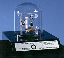
A replica of the first working transistor, a point-contact transistor
 
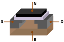
Metal–oxide–semiconductor field-effect transistor (MOSFET), the basic building block of modern electronics

The first working transistor was a point-contact transistor invented by John Bardeen and Walter Houser Brattain while working under William Shockley at the Bell Telephone Laboratories (BTL) in 1947. They then invented the bipolar junction transistor in 1948. While early junction transistors were relatively bulky devices that were difficult to manufacture on a mass-production basis, they opened the door for more compact devices.

The first integrated circuits were the hybrid integrated circuit invented by Jack Kilby at Texas Instruments in 1958 and the monolithic integrated circuit chip invented by Robert Noyce at Fairchild Semiconductor in 1959.

The MOSFET (metal-oxide-semiconductor field-effect transistor, or MOS transistor) was invented by Mohamed Atalla and Dawon Kahng at BTL in 1959. It was the first truly compact transistor that could be miniaturised and mass-produced for a wide range of uses. It revolutionized the electronics industry, becoming the most widely used electronic device in the world.

The MOSFET made it possible to build high-density integrated circuit chips. The earliest experimental MOS IC chip to be fabricated was built by Fred Heiman and Steven Hofstein at RCA Laboratories in 1962. MOS technology enabled Moore's law, the doubling of transistors on an IC chip every two years, predicted by Gordon Moore in 1965. Silicon-gate MOS technology was developed by Federico Faggin at Fairchild in 1968. Since then, the MOSFET has been the basic building block of modern electronics. The mass-production of silicon MOSFETs and MOS integrated circuit chips, along with continuous MOSFET scaling miniaturization at an exponential pace (as predicted by Moore's law), has since led to revolutionary changes in technology, economy, culture and thinking.

The Apollo program which culminated in landing astronauts on the Moon with Apollo 11 in 1969 was enabled by NASA's adoption of advances in semiconductor electronic technology, including MOSFETs in the Interplanetary Monitoring Platform (IMP) and silicon integrated circuit chips in the Apollo Guidance Computer (AGC).

The development of MOS integrated circuit technology in the 1960s led to the invention of the microprocessor in the early 1970s. The first single-chip microprocessor was the Intel 4004, released in 1971. The Intel 4004 was designed and realized by Federico Faggin at Intel with his silicon-gate MOS technology, along with Intel's Marcian Hoff and Stanley Mazor and Busicom's Masatoshi Shima. The microprocessor led to the development of microcomputers and personal computers, and the microcomputer revolution.

Subfields

One of the properties of electricity is that it is very useful for energy transmission as well as for information transmission. These were also the first areas in which electrical engineering was developed. Today electrical engineering has many subdisciplines, the most common of which are listed below. Although there are electrical engineers who focus exclusively on one of these subdisciplines, many deal with a combination of them. Sometimes certain fields, such as electronic engineering and computer engineering, are considered disciplines in their own right.

Power and energy

The top of a power pole

Power & Energy engineering deals with the generation, transmission, and distribution of electricity as well as the design of a range of related devices. These include transformers, electric generators, electric motors, high voltage engineering, and power electronics. In many regions of the world, governments maintain an electrical network called a power grid that connects a variety of generators together with users of their energy. Users purchase electrical energy from the grid, avoiding the costly exercise of having to generate their own. Power engineers may work on the design and maintenance of the power grid as well as the power systems that connect to it. Such systems are called on-grid power systems and may supply the grid with additional power, draw power from the grid, or do both. Power engineers may also work on systems that do not connect to the grid, called off-grid power systems, which in some cases are preferable to on-grid systems. The future includes Satellite controlled power systems, with feedback in real time to prevent power surges and prevent blackouts.

Telecommunications

Satellite dishes are a crucial component in the analysis of satellite information.

Telecommunications engineering focuses on the transmission of information across a communication channel such as a coax cable, optical fiber or free space. Transmissions across free space require information to be encoded in a carrier signal to shift the information to a carrier frequency suitable for transmission; this is known as modulation. Popular analog modulation techniques include amplitude modulation and frequency modulation. The choice of modulation affects the cost and performance of a system and these two factors must be balanced carefully by the engineer.

Once the transmission characteristics of a system are determined, telecommunication engineers design the transmitters and receivers needed for such systems. These two are sometimes combined to form a two-way communication device known as a transceiver. A key consideration in the design of transmitters is their power consumption as this is closely related to their signal strength. Typically, if the power of the transmitted signal is insufficient once the signal arrives at the receiver's antenna(s), the information contained in the signal will be corrupted by noise, specifically static.

Control engineering

Control systems play a critical role in spaceflight.

Control engineering focuses on the modeling of a diverse range of dynamic systems and the design of controllers that will cause these systems to behave in the desired manner. To implement such controllers, electronics control engineers may use electronic circuits, digital signal processors, microcontrollers, and programmable logic controllers (PLCs). Control engineering has a wide range of applications from the flight and propulsion systems of commercial airliners to the cruise control present in many modern automobiles. It also plays an important role in industrial automation.

Control engineers often use feedback when designing control systems. For example, in an automobile with cruise control the vehicle's speed is continuously monitored and fed back to the system which adjusts the motor's power output accordingly. Where there is regular feedback, control theory can be used to determine how the system responds to such feedback.

Control engineers also work in robotics to design autonomous systems using control algorithms which interpret sensory feedback to control actuators that move robots such as autonomous vehicles, autonomous drones and others used in a variety of industries.

Electronics

Electronic engineering involves the design and testing of electronic circuits that use the properties of components such as resistors, capacitors, inductors, diodes, and transistors to achieve a particular functionality. The tuned circuit, which allows the user of a radio to filter out all but a single station, is just one example of such a circuit. Another example to research is a pneumatic signal conditioner.

Prior to the Second World War, the subject was commonly known as radio engineering and basically was restricted to aspects of communications and radar, commercial radio, and early television. Later, in post-war years, as consumer devices began to be developed, the field grew to include modern television, audio systems, computers, and microprocessors. In the mid-to-late 1950s, the term radio engineering gradually gave way to the name electronic engineering.

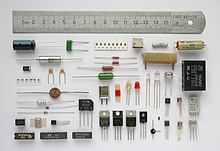
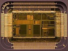
Before the invention of the integrated circuit in 1959, electronic circuits were constructed from discrete components that could be manipulated by humans. These discrete circuits consumed much space and power and were limited in speed, although they are still common in some applications. By contrast, integrated circuits packed a large number—often millions—of tiny electrical components, mainly transistors, into a small chip around the size of a coin. This allowed for the powerful computers and other electronic devices we see today.

Microelectronics and nanoelectronics

Microelectronics engineering deals with the design and microfabrication of very small electronic circuit components for use in an integrated circuit or sometimes for use on their own as a general electronic component. The most common microelectronic components are semiconductor transistors, although all main electronic components (resistors, capacitors etc.) can be created at a microscopic level.

Nanoelectronics is the further scaling of devices down to nanometer levels. Modern devices are already in the nanometer regime, with below 100 nm processing having been standard since around 2002.

Microelectronic components are created by chemically fabricating wafers of semiconductors such as silicon (at higher frequencies, compound semiconductors like gallium arsenide and indium phosphide) to obtain the desired transport of electronic charge and control of current. The field of microelectronics involves a significant amount of chemistry and material science and requires the electronic engineer working in the field to have a very good working knowledge of the effects of quantum mechanics.

Signal processing

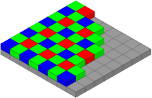
A Bayer filter on a CCD requires signal processing to get a red, green, and blue value at each pixel.

Signal processing deals with the analysis and manipulation of signals. Signals can be either analog, in which case the signal varies continuously according to the information, or digital, in which case the signal varies according to a series of discrete values representing the information. For analog signals, signal processing may involve the amplification and filtering of audio signals for audio equipment or the modulation and demodulation of signals for telecommunications. For digital signals, signal processing may involve the compression, error detection and error correction of digitally sampled signals.

Signal Processing is a very mathematically oriented and intensive area forming the core of digital signal processing and it is rapidly expanding with new applications in every field of electrical engineering such as communications, control, radar, audio engineering, broadcast engineering, power electronics, and biomedical engineering as many already existing analog systems are replaced with their digital counterparts. Analog signal processing is still important in the design of many control systems.

DSP processor ICs are found in many types of modern electronic devices, such as digital television sets, radios, Hi-Fi audio equipment, mobile phones, multimedia players, camcorders and digital cameras, automobile control systems, noise cancelling headphones, digital spectrum analyzers, missile guidance systems, radar systems, and telematics systems. In such products, DSP may be responsible for noise reduction, speech recognition or synthesis, encoding or decoding digital media, wirelessly transmitting or receiving data, triangulating positions using GPS, and other kinds of image processing, video processing, audio processing, and speech processing.

Instrumentation

Flight instruments provide pilots with the tools to control aircraft analytically.

Instrumentation engineering deals with the design of devices to measure physical quantities such as pressure, flow, and temperature. The design of such instruments requires a good understanding of physics that often extends beyond electromagnetic theory. For example, flight instruments measure variables such as wind speed and altitude to enable pilots the control of aircraft analytically. Similarly, thermocouples use the Peltier-Seebeck effect to measure the temperature difference between two points.

Often instrumentation is not used by itself, but instead as the sensors of larger electrical systems. For example, a thermocouple might be used to help ensure a furnace's temperature remains constant. For this reason, instrumentation engineering is often viewed as the counterpart of control.

Computers

Computer engineering deals with the design of computers and computer systems. This may involve the design of new hardware. Computer engineers may also work on a system's software. However, the design of complex software systems is often the domain of software engineering, which is usually considered a separate discipline. Desktop computers represent a tiny fraction of the devices a computer engineer might work on, as computer-like architectures are now found in a range of embedded devices including video game consoles and DVD players. Computer engineers are involved in many hardware and software aspects of computing. Robots are one of the applications of computer engineering.

Photonics and optics

Photonics and optics deals with the generation, transmission, amplification, modulation, detection, and analysis of electromagnetic radiation. The application of optics deals with design of optical instruments such as lenses, microscopes, telescopes, and other equipment that uses the properties of electromagnetic radiation. Other prominent applications of optics include electro-optical sensors and measurement systems, lasers, fiber optic communication systems, and optical disc systems (e.g. CD and DVD). Photonics builds heavily on optical technology, supplemented with modern developments such as optoelectronics (mostly involving semiconductors), laser systems, optical amplifiers and novel materials (e.g. metamaterials).

Related disciplines

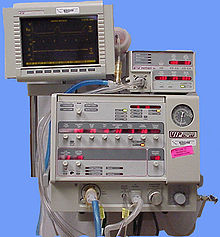
The Bird VIP Infant ventilator

Mechatronics is an engineering discipline which deals with the convergence of electrical and mechanical systems. Such combined systems are known as electromechanical systems and have widespread adoption. Examples include automated manufacturing systems, heating, ventilation and air-conditioning systems, and various subsystems of aircraft and automobilesElectronic systems design is the subject within electrical engineering that deals with the multi-disciplinary design issues of complex electrical and mechanical systems.

The term mechatronics is typically used to refer to macroscopic systems but futurists have predicted the emergence of very small electromechanical devices. Already, such small devices, known as Microelectromechanical systems (MEMS), are used in automobiles to tell airbags when to deploy, in digital projectors to create sharper images, and in inkjet printers to create nozzles for high definition printing. In the future it is hoped the devices will help build tiny implantable medical devices and improve optical communication.

In Aerospace engineering and robotics, an example is the most recent electric propulsion and ion propulsion.

Education

Electrical engineers typically possess an academic degree with a major in electrical engineering, electronics engineering, electrical engineering technology, or electrical and electronic engineering. The same fundamental principles are taught in all programs, though emphasis may vary according to title. The length of study for such a degree is usually four or five years and the completed degree may be designated as a Bachelor of Science in Electrical/Electronics Engineering Technology, Bachelor of Engineering, Bachelor of Science, Bachelor of Technology, or Bachelor of Applied Science, depending on the university. The bachelor's degree generally includes units covering physics, mathematics, computer science, project management, and a variety of topics in electrical engineering. Initially such topics cover most, if not all, of the subdisciplines of electrical engineering. At some schools, the students can then choose to emphasize one or more subdisciplines towards the end of their courses of study.

An example circuit diagram, which is useful in circuit design and troubleshooting.

At many schools, electronic engineering is included as part of an electrical award, sometimes explicitly, such as a Bachelor of Engineering (Electrical and Electronic), but in others, electrical and electronic engineering are both considered to be sufficiently broad and complex that separate degrees are offered.

Some electrical engineers choose to study for a postgraduate degree such as a Master of Engineering/Master of Science (MEng/MSc), a Master of Engineering Management, a Doctor of Philosophy (PhD) in Engineering, an Engineering Doctorate (Eng.D.), or an Engineer's degree. The master's and engineer's degrees may consist of either research, coursework or a mixture of the two. The Doctor of Philosophy and Engineering Doctorate degrees consist of a significant research component and are often viewed as the entry point to academia. In the United Kingdom and some other European countries, Master of Engineering is often considered to be an undergraduate degree of slightly longer duration than the Bachelor of Engineering rather than a standalone postgraduate degree.

Professional practice

Belgian electrical engineers inspecting the rotor of a 40,000 kilowatt turbine of the General Electric Company in New York City

In most countries, a bachelor's degree in engineering represents the first step towards professional certification and the degree program itself is certified by a professional body. After completing a certified degree program the engineer must satisfy a range of requirements (including work experience requirements) before being certified. Once certified the engineer is designated the title of Professional Engineer (in the United States, Canada and South Africa), Chartered engineer or Incorporated Engineer (in India, Pakistan, the United Kingdom, Ireland and Zimbabwe), Chartered Professional Engineer (in Australia and New Zealand) or European Engineer (in much of the European Union).

The IEEE corporate office is on the 17th floor of 3 Park Avenue in New York City

The advantages of licensure vary depending upon location. For example, in the United States and Canada "only a licensed engineer may seal engineering work for public and private clients". This requirement is enforced by state and provincial legislation such as Quebec's Engineers Act. In other countries, no such legislation exists. Practically all certifying bodies maintain a code of ethics that they expect all members to abide by or risk expulsion. In this way these organizations play an important role in maintaining ethical standards for the profession. Even in jurisdictions where certification has little or no legal bearing on work, engineers are subject to contract law. In cases where an engineer's work fails he or she may be subject to the tort of negligence and, in extreme cases, the charge of criminal negligence. An engineer's work must also comply with numerous other rules and regulations, such as building codes and legislation pertaining to environmental law.

Professional bodies of note for electrical engineers include the Institute of Electrical and Electronics Engineers (IEEE) and the Institution of Engineering and Technology (IET). The IEEE claims to produce 30% of the world's literature in electrical engineering, has over 360,000 members worldwide and holds over 3,000 conferences annually. The IET publishes 21 journals, has a worldwide membership of over 150,000, and claims to be the largest professional engineering society in Europe. Obsolescence of technical skills is a serious concern for electrical engineers. Membership and participation in technical societies, regular reviews of periodicals in the field and a habit of continued learning are therefore essential to maintaining proficiency. An MIET(Member of the Institution of Engineering and Technology) is recognised in Europe as an Electrical and computer (technology) engineer.

In Australia, Canada, and the United States electrical engineers make up around 0.25% of the labor force.

Tools and work

From the Global Positioning System to electric power generation, electrical engineers have contributed to the development of a wide range of technologies. They design, develop, test, and supervise the deployment of electrical systems and electronic devices. For example, they may work on the design of telecommunication systems, the operation of electric power stations, the lighting and wiring of buildings, the design of household appliances, or the electrical control of industrial machinery.

Satellite communications is typical of what electrical engineers work on.

Fundamental to the discipline are the sciences of physics and mathematics as these help to obtain both a qualitative and quantitative description of how such systems will work. Today most engineering work involves the use of computers and it is commonplace to use computer-aided design programs when designing electrical systems. Nevertheless, the ability to sketch ideas is still invaluable for quickly communicating with others.

Although most electrical engineers will understand basic circuit theory (that is the interactions of elements such as resistors, capacitors, diodes, transistors, and inductors in a circuit), the theories employed by engineers generally depend upon the work they do. For example, quantum mechanics and solid state physics might be relevant to an engineer working on VLSI (the design of integrated circuits), but are largely irrelevant to engineers working with macroscopic electrical systems. Even circuit theory may not be relevant to a person designing telecommunication systems that use off-the-shelf components. Perhaps the most important technical skills for electrical engineers are reflected in university programs, which emphasize strong numerical skills, computer literacy, and the ability to understand the technical language and concepts that relate to electrical engineering.

A laser bouncing down an acrylic rod, illustrating the total internal reflection of light in a multi-mode optical fiber.

A wide range of instrumentation is used by electrical engineers. For simple control circuits and alarms, a basic multimeter measuring voltage, current, and resistance may suffice. Where time-varying signals need to be studied, the oscilloscope is also an ubiquitous instrument. In RF engineering and high frequency telecommunications, spectrum analyzers and network analyzers are used. In some disciplines, safety can be a particular concern with instrumentation. For instance, medical electronics designers must take into account that much lower voltages than normal can be dangerous when electrodes are directly in contact with internal body fluids. Power transmission engineering also has great safety concerns due to the high voltages used; although voltmeters may in principle be similar to their low voltage equivalents, safety and calibration issues make them very different. Many disciplines of electrical engineering use tests specific to their discipline. Audio electronics engineers use audio test sets consisting of a signal generator and a meter, principally to measure level but also other parameters such as harmonic distortion and noise. Likewise, information technology have their own test sets, often specific to a particular data format, and the same is true of television broadcasting.

Radome at the Misawa Air Base Misawa Security Operations Center, Misawa, Japan

For many engineers, technical work accounts for only a fraction of the work they do. A lot of time may also be spent on tasks such as discussing proposals with clients, preparing budgets and determining project schedules. Many senior engineers manage a team of technicians or other engineers and for this reason project management skills are important. Most engineering projects involve some form of documentation and strong written communication skills are therefore very important.

The workplaces of engineers are just as varied as the types of work they do. Electrical engineers may be found in the pristine lab environment of a fabrication plant, on board a Naval ship, the offices of a consulting firm or on site at a mine. During their working life, electrical engineers may find themselves supervising a wide range of individuals including scientists, electricians, computer programmers, and other engineers.

Electrical engineering has an intimate relationship with the physical sciences. For instance, the physicist Lord Kelvin played a major role in the engineering of the first transatlantic telegraph cable. Conversely, the engineer Oliver Heaviside produced major work on the mathematics of transmission on telegraph cables. Electrical engineers are often required on major science projects. For instance, large particle accelerators such as CERN need electrical engineers to deal with many aspects of the project including the power distribution, the instrumentation, and the manufacture and installation of the superconducting electromagnets.

History of life

From Wikipedia, the free encyclopedia https://en.wikipedia.org/wiki/History_of_life Part of a series on Evo...