Search This Blog

Thursday, May 25, 2023

Natural nuclear fission reactor

From Wikipedia, the free encyclopedia
 
Geological situation in Gabon leading to natural nuclear fission reactors
  1. Nuclear reactor zones
  2. Sandstone
  3. Uranium ore layer
  4. Granite

A natural nuclear fission reactor is a uranium deposit where self-sustaining nuclear chain reactions occur. The conditions under which a natural nuclear reactor could exist had been predicted in 1956 by Paul Kuroda. The remnants of an extinct or fossil nuclear fission reactor, where self-sustaining nuclear reactions have occurred in the past, can be verified by analysis of isotope ratios of uranium and of the fission products (and the stable daughter nuclides of those fission products). An example of this phenomenon was discovered in 1972 in Oklo, Gabon by Francis Perrin under conditions very similar to Kuroda's predictions.

Oklo is the only location where this phenomenon is known to have occurred, and consists of 16 sites with patches of centimeter-sized ore layers. Here self-sustaining nuclear fission reactions are thought to have taken place approximately 1.7 billion years ago, during the Statherian period of the Paleoproterozoic, and continued for a few hundred thousand years, probably averaging less than 100 kW of thermal power during that time.

History

In May 1972 at the Tricastin uranium enrichment site at Pierrelatte in France, routine mass spectrometry comparing UF6 samples from the Oklo Mine, located in Gabon, showed a discrepancy in the amount of the 235
U
isotope. Normally the concentration is 0.72% while these samples had only 0.60%, a significant difference (some 17% less U-235 was contained in the samples than expected). This discrepancy required explanation, as all civilian uranium handling facilities must meticulously account for all fissionable isotopes to ensure that none are diverted to the construction of nuclear weapons. Furthermore since fissile material is why people mine uranium, a significant amount "going missing" was also of direct economic concern.

Thus the French Commissariat à l'énergie atomique (CEA) began an investigation. A series of measurements of the relative abundances of the two most significant isotopes of the uranium mined at Oklo showed anomalous results compared to those obtained for uranium from other mines. Further investigations into this uranium deposit discovered uranium ore with a 235
U
concentration as low as 0.44% (almost 40% below the normal value). Subsequent examination of isotopes of fission products such as neodymium and ruthenium also showed anomalies, as described in more detail below. However, the trace radioisotope 234
U
did not deviate significantly in its concentration from other natural samples. Both depleted uranium and reprocessed uranium will usually have 234
U
concentrations significantly different from the secular equilibrium of 55 ppm 234
U
relative to 238
U
. This is due to 234
U
being enriched together with 235
U
and due to it being both consumed by neutron capture and produced from 235
U
by fast neutron induced (n,2n) reactions in nuclear reactors. In Oklo any possible deviation of 234
U
concentration present at the time the reactor was active would have long since decayed away. 236
U
must have also been present in higher than usual ratios during the time the reactor was operating, but due to its half life of 2.348×10⁷ years being almost two orders of magnitude shorter than the time elapsed since the reactor operated, it has decayed to roughly 1.4×10⁻²² its original value and thus basically nothing and below any abilities of current equipment to detect.

This loss in 235
U
is exactly what happens in a nuclear reactor. A possible explanation was that the uranium ore had operated as a natural fission reactor in the distant geological past. Other observations led to the same conclusion, and on 25 September 1972 the CEA announced their finding that self-sustaining nuclear chain reactions had occurred on Earth about 2 billion years ago. Later, other natural nuclear fission reactors were discovered in the region.

Fission product isotope signatures

Isotope signatures of natural neodymium and fission product neodymium from 235
U
which had been subjected to thermal neutrons.

Neodymium

Neodymium and other elements were found with isotopic compositions different from what is usually found on Earth. For example, Oklo contained less than 6% of the 142
Nd
isotope while natural neodymium contains 27%; however Oklo contained more of the 143
Nd
isotope. Subtracting the natural isotopic Nd abundance from the Oklo-Nd, the isotopic composition matched that produced by the fission of 235
U
.

Ruthenium

Isotope signatures of natural ruthenium and fission product ruthenium from 235
U
which had been subjected to thermal neutrons. The 100
Mo
(an extremely long-lived double beta emitter) has not had time to decay to 100
Ru
in more than trace quantities over the time since the reactors stopped working.

Similar investigations into the isotopic ratios of ruthenium at Oklo found a much higher 99
Ru
concentration than otherwise naturally occurring (27–30% vs. 12.7%). This anomaly could be explained by the decay of 99
Tc
to 99
Ru
. In the bar chart the normal natural isotope signature of ruthenium is compared with that for fission product ruthenium which is the result of the fission of 235
U
with thermal neutrons. It is clear that the fission ruthenium has a different isotope signature. The level of 100
Ru
in the fission product mixture is low because fission produces neutron rich isotopes which subsequently beta decay and 100
Ru
would only be produced in appreciable quantities by double beta decay of the very long-lived (half life 7.1×10¹⁸ years) molybdenum isotope 100
Mo
. On the timescale of when the reactors were in operation, very little (about 0.17 ppb) decay to 100
Ru
will have occurred. Other pathways of 100
Ru
production like neutron capture in 99
Ru
or 99
Tc
(quickly followed by beta decay) can only have occurred during high neutron flux and thus ceased when the fission chain reaction stopped.

Mechanism

The natural nuclear reactor formed when a uranium-rich mineral deposit became inundated with groundwater, which could act as a moderator for the neutrons produced by nuclear fission. A chain reaction took place, producing heat that caused the groundwater to boil away; without a moderator that could slow the neutrons, however, the reaction slowed or stopped. The reactor thus had a negative void coefficient of reactivity, something employed as a safety mechanism in human-made light water reactors. After cooling of the mineral deposit, the water returned, and the reaction restarted, completing a full cycle every 3 hours. The fission reaction cycles continued for hundreds of thousands of years and ended when the ever-decreasing fissile materials, coupled with the build-up of neutron poisons, no longer could sustain a chain reaction.

Fission of uranium normally produces five known isotopes of the fission-product gas xenon; all five have been found trapped in the remnants of the natural reactor, in varying concentrations. The concentrations of xenon isotopes, found trapped in mineral formations 2 billion years later, make it possible to calculate the specific time intervals of reactor operation: approximately 30 minutes of criticality followed by 2 hours and 30 minutes of cooling down (exponentially decreasing residual decay heat) to complete a 3-hour cycle. Xenon-135 is the strongest known neutron poison. However, it is not produced directly in appreciable amounts but rather as a decay product of Iodine-135 (or one of its parent nuclides). Xenon-135 itself is unstable and decays to Caesium-135 if not allowed to absorb neutrons. While Caesium-135 is relatively long lived, all Caesium-135 produced by the Oklo reactor has since decayed further to stable Barium-135. Meanwhile Xenon-136, the product of neutron capture in Xenon-135 only decays extremely slowly via double beta decay and thus scientists were able to determine the neutronics of this reactor by calculations based on those isotope ratios almost two billion years after it stopped fissioning uranium.

A key factor that made the reaction possible was that, at the time the reactor went critical 1.7 billion years ago, the fissile isotope 235
U
made up about 3.1% of the natural uranium, which is comparable to the amount used in some of today's reactors. (The remaining 96.9% was non-fissile 238
U
and roughly 55 ppm 234
U
.) Because 235
U
has a shorter half-life than 238
U
, and thus decays more rapidly, the current abundance of 235
U
in natural uranium is only 0.72%. A natural nuclear reactor is therefore no longer possible on Earth without heavy water or graphite.

The Oklo uranium ore deposits are the only known sites in which natural nuclear reactors existed. Other rich uranium ore bodies would also have had sufficient uranium to support nuclear reactions at that time, but the combination of uranium, water and physical conditions needed to support the chain reaction was unique, as far as is currently known, to the Oklo ore bodies. It is also possible, that other natural nuclear fission reactors were once operating but have since been geologically disturbed so much as to be unrecognizable, possibly even "diluting" the uranium so far that the isotope ratio would no longer serve as a "fingerprint". Only a small part of the continental crust and no part of the oceanic crust reaches the age of the deposits at Oklo or an age during which isotope ratios of natural uranium would have allowed a self sustaining chain reaction with water as a moderator.

Another factor which probably contributed to the start of the Oklo natural nuclear reactor at 2 billion years, rather than earlier, was the increasing oxygen content in the Earth's atmosphere. Uranium is naturally present in the rocks of the earth, and the abundance of fissile 235
U
was at least 3% or higher at all times prior to reactor startup. Uranium is soluble in water only in the presence of oxygen. Therefore, increasing oxygen levels during the aging of the Earth may have allowed uranium to be dissolved and transported with groundwater to places where a high enough concentration could accumulate to form rich uranium ore bodies. Without the new aerobic environment available on Earth at the time, these concentrations probably could not have taken place.

It is estimated that nuclear reactions in the uranium in centimeter- to meter-sized veins consumed about five tons of 235
U
and elevated temperatures to a few hundred degrees Celsius. Most of the non-volatile fission products and actinides have only moved centimeters in the veins during the last 2 billion years. Studies have suggested this as a useful natural analogue for nuclear waste disposal. The overall mass defect from the fission of five tons of 235
U
is about 4.6 kilograms (10 lb). Over its lifetime the reactor produced roughly 100 megatonnes of TNT (420 PJ) in thermal energy, including neutrinos. If one ignores fission of plutonium (which makes up roughly a third of fission events over the course of normal burnup in modern humanmade light water reactors), then fission product yields amount to roughly 129 kilograms (284 lb) of Technetium-99 (since decayed to Ruthenium-99) 108 kilograms (238 lb) of Zirconium-93 (since decayed to Niobium-93), 198 kilograms (437 lb) of Caesium-135 (since decayed to Barium-135, but the real value is probably lower as its parent nuclide, Xenon-135, is a strong neutron poison and will have absorbed neutrons before decaying to Cs-135 in some cases), 28 kilograms (62 lb) of Palladium-107 (since decayed to Silver), 86 kilograms (190 lb) of Strontium-90 (long since decayed to Zirconium) and 185 kilograms (408 lb) of Caesium-137 (long since decayed to Barium).

Relation to the atomic fine-structure constant

The natural reactor of Oklo has been used to check if the atomic fine-structure constant α might have changed over the past 2 billion years. That is because α influences the rate of various nuclear reactions. For example, 149
Sm
captures a neutron to become 150
Sm
, and since the rate of neutron capture depends on the value of α, the ratio of the two samarium isotopes in samples from Oklo can be used to calculate the value of α from 2 billion years ago.

Several studies have analysed the relative concentrations of radioactive isotopes left behind at Oklo, and most have concluded that nuclear reactions then were much the same as they are today, which implies α was the same too.

Photodiode

From Wikipedia, the free encyclopedia
 
Fotodio.jpg
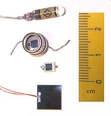
One Ge (top) and three Si (bottom) photodiodes
TypePassive, diode
Working principleConverts light into current
Pin configuration anode and cathode
Electronic symbol
IEEE 315-1975 (1993) 8.5.4.1.svg

A photodiode is a light-sensitive semiconductor diode. It produces current when it absorbs photons.

The package of a photodiode allows light (or infrared or ultraviolet radiation, or X-rays) to reach the sensitive part of the device. The package may include lenses or optical filters. Devices designed for use specially as a photodiode use a PIN junction rather than a p–n junction, to increase the speed of response. Photodiodes usually have a slower response time as their surface area increases. A photodiode is designed to operate in reverse bias. A solar cell used to generate electric solar power is a large area photodiode.

Photodiodes are used in scientific and industrial instruments to measure light intensity, either for its own sake or as a measure of some other property (density of smoke, for example). A photodiode can be used as the receiver of data encoded on an infrared beam, as in household remote controls. Photodiodes can be used to form an optocoupler, allowing transmission of signals between circuits without a direct metallic connection between them, allowing isolation from high voltage differences.

Principle of operation

A photodiode is a PIN structure or p–n junction. When a photon of sufficient energy strikes the diode, it creates an electronhole pair. This mechanism is also known as the inner photoelectric effect. If the absorption occurs in the junction's depletion region, or one diffusion length away from it, these carriers are swept from the junction by the built-in electric field of the depletion region. Thus holes move toward the anode, and electrons toward the cathode, and a photocurrent is produced. The total current through the photodiode is the sum of the dark current (current that is generated in the absence of light) and the photocurrent, so the dark current must be minimized to maximize the sensitivity of the device.

To first order, for a given spectral distribution, the photocurrent is linearly proportional to the irradiance.

Photovoltaic mode

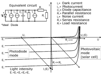
I-V characteristic of a photodiode. The linear load lines represent the response of the external circuit: I=(Applied bias voltage-Diode voltage)/Total resistance. The points of intersection with the curves represent the actual current and voltage for a given bias, resistance and illumination.

In photovoltaic mode (zero bias), photocurrent flows into the anode through a short circuit to the cathode. If the circuit is opened or has a load impedance, restricting the photocurrent out of the device, a voltage builds up in the direction that forward biases the diode, that is, anode positive with respect to cathode. If the circuit is shorted or the impedance is low, a forward current will consume all or some of the photocurrent. This mode exploits the photovoltaic effect, which is the basis for solar cells – a traditional solar cell is just a large area photodiode. For optimum power output, the photovoltaic cell will be operated at a voltage that causes only a small forward current compared to the photocurrent.

Photoconductive mode

In photoconductive mode the diode is reverse biased, that is, with the cathode driven positive with respect to the anode. This reduces the response time because the additional reverse bias increases the width of the depletion layer, which decreases the junction's capacitance and increases the region with an electric field that will cause electrons to be quickly collected. The reverse bias also creates dark current without much change in the photocurrent.

Although this mode is faster, the photoconductive mode can exhibit more electronic noise due to dark current or avalanche effects. The leakage current of a good PIN diode is so low (<1 nA) that the Johnson–Nyquist noise of the load resistance in a typical circuit often dominates.

Related devices

Avalanche photodiodes are photodiodes with structure optimized for operating with high reverse bias, approaching the reverse breakdown voltage. This allows each photo-generated carrier to be multiplied by avalanche breakdown, resulting in internal gain within the photodiode, which increases the effective responsivity of the device.

Electronic symbol for a phototransistor

A phototransistor is a light-sensitive transistor. A common type of phototransistor, the bipolar phototransistor, is in essence a bipolar transistor encased in a transparent case so that light can reach the base–collector junction. It was invented by Dr. John N. Shive (more famous for his wave machine) at Bell Labs in 1948 but it was not announced until 1950. The electrons that are generated by photons in the base–collector junction are injected into the base, and this photodiode current is amplified by the transistor's current gain β (or hfe). If the base and collector leads are used and the emitter is left unconnected, the phototransistor becomes a photodiode. While phototransistors have a higher responsivity for light they are not able to detect low levels of light any better than photodiodes. Phototransistors also have significantly longer response times. Another type of phototransistor, the field-effect phototransistor (also known as photoFET), is a light-sensitive field-effect transistor. Unlike photobipolar transistors, photoFETs control drain-source current by creating a gate voltage.

A solaristor is a two-terminal gate-less phototransistor. A compact class of two-terminal phototransistors or solaristors have been demonstrated in 2018 by ICN2 researchers. The novel concept is a two-in-one power source plus transistor device that runs on solar energy by exploiting a memresistive effect in the flow of photogenerated carriers.

Materials

The material used to make a photodiode is critical to defining its properties, because only photons with sufficient energy to excite electrons across the material's bandgap will produce significant photocurrents.

Materials commonly used to produce photodiodes are listed in the table below.

Material Electromagnetic spectrum
wavelength range (nm)
Silicon 190–1100
Germanium 400–1700
Indium gallium arsenide 800–2600
Lead(II) sulfide <1000–3500
Mercury cadmium telluride 400–14000

Because of their greater bandgap, silicon-based photodiodes generate less noise than germanium-based photodiodes.

Binary materials, such as MoS2, and graphene emerged as new materials for the production of photodiodes.

Unwanted and wanted photodiode effects

Any p–n junction, if illuminated, is potentially a photodiode. Semiconductor devices such as diodes, transistors and ICs contain p–n junctions, and will not function correctly if they are illuminated by unwanted electromagnetic radiation (light) of wavelength suitable to produce a photocurrent. This is avoided by encapsulating devices in opaque housings. If these housings are not completely opaque to high-energy radiation (ultraviolet, X-rays, gamma rays), diodes, transistors and ICs can malfunction due to induced photo-currents. Background radiation from the packaging is also significant. Radiation hardening mitigates these effects.

In some cases, the effect is actually wanted, for example to use LEDs as light-sensitive devices (see LED as light sensor) or even for energy harvesting, then sometimes called light-emitting and light-absorbing diodes (LEADs).

Features

Response of a silicon photo diode vs wavelength of the incident light

Critical performance parameters of a photodiode include spectral responsivity, dark current, response time and noise-equivalent power.

Spectral responsivity
The spectral responsivity is a ratio of the generated photocurrent to incident light power, expressed in A/W when used in photoconductive mode. The wavelength-dependence may also be expressed as a quantum efficiency or the ratio of the number of photogenerated carriers to incident photons which is a unitless quantity.
Dark current
The dark current is the current through the photodiode in the absence of light, when it is operated in photoconductive mode. The dark current includes photocurrent generated by background radiation and the saturation current of the semiconductor junction. Dark current must be accounted for by calibration if a photodiode is used to make an accurate optical power measurement, and it is also a source of noise when a photodiode is used in an optical communication system.
Response time
The response time is the time required for the detector to respond to an optical input. A photon absorbed by the semiconducting material will generate an electron–hole pair which will in turn start moving in the material under the effect of the electric field and thus generate a current. The finite duration of this current is known as the transit-time spread and can be evaluated by using Ramo's theorem. One can also show with this theorem that the total charge generated in the external circuit is e and not 2e as one might expect by the presence of the two carriers. Indeed, the integral of the current due to both electron and hole over time must be equal to e. The resistance and capacitance of the photodiode and the external circuitry give rise to another response time known as RC time constant (). This combination of R and C integrates the photoresponse over time and thus lengthens the impulse response of the photodiode. When used in an optical communication system, the response time determines the bandwidth available for signal modulation and thus data transmission.
Noise-equivalent power
Noise-equivalent power (NEP) is the minimum input optical power to generate photocurrent, equal to the rms noise current in a 1 hertz bandwidth. NEP is essentially the minimum detectable power. The related characteristic detectivity () is the inverse of NEP (1/NEP) and the specific detectivity () is the detectivity multiplied by the square root of the area () of the photodetector () for a 1 Hz bandwidth. The specific detectivity allows different systems to be compared independent of sensor area and system bandwidth; a higher detectivity value indicates a low-noise device or system. Although it is traditional to give () in many catalogues as a measure of the diode's quality, in practice, it is hardly ever the key parameter.

When a photodiode is used in an optical communication system, all these parameters contribute to the sensitivity of the optical receiver which is the minimum input power required for the receiver to achieve a specified bit error rate.

Applications

P–n photodiodes are used in similar applications to other photodetectors, such as photoconductors, charge-coupled devices (CCD), and photomultiplier tubes. They may be used to generate an output which is dependent upon the illumination (analog for measurement), or to change the state of circuitry (digital, either for control and switching or for digital signal processing).

Photodiodes are used in consumer electronics devices such as compact disc players, smoke detectors, medical devices and the receivers for infrared remote control devices used to control equipment from televisions to air conditioners. For many applications either photodiodes or photoconductors may be used. Either type of photosensor may be used for light measurement, as in camera light meters, or to respond to light levels, as in switching on street lighting after dark.

Photosensors of all types may be used to respond to incident light or to a source of light which is part of the same circuit or system. A photodiode is often combined into a single component with an emitter of light, usually a light-emitting diode (LED), either to detect the presence of a mechanical obstruction to the beam (slotted optical switch) or to couple two digital or analog circuits while maintaining extremely high electrical isolation between them, often for safety (optocoupler). The combination of LED and photodiode is also used in many sensor systems to characterize different types of products based on their optical absorbance.

Photodiodes are often used for accurate measurement of light intensity in science and industry. They generally have a more linear response than photoconductors.

They are also widely used in various medical applications, such as detectors for computed tomography (coupled with scintillators), instruments to analyze samples (immunoassay), and pulse oximeters.

PIN diodes are much faster and more sensitive than p–n junction diodes, and hence are often used for optical communications and in lighting regulation.

P–n photodiodes are not used to measure extremely low light intensities. Instead, if high sensitivity is needed, avalanche photodiodes, intensified charge-coupled devices or photomultiplier tubes are used for applications such as astronomy, spectroscopy, night vision equipment and laser rangefinding.

Comparison with photomultipliers

Advantages compared to photomultipliers:

  1. Excellent linearity of output current as a function of incident light
  2. Spectral response from 190 nm to 1100 nm (silicon), longer wavelengths with other semiconductor materials
  3. Low noise
  4. Ruggedized to mechanical stress
  5. Low cost
  6. Compact and light weight
  7. Long lifetime
  8. High quantum efficiency, typically 60–80%
  9. No high voltage required

Disadvantages compared to photomultipliers:

  1. Small area
  2. No internal gain (except avalanche photodiodes, but their gain is typically 102–103 compared to 105-108 for the photomultiplier)
  3. Much lower overall sensitivity
  4. Photon counting only possible with specially designed, usually cooled photodiodes, with special electronic circuits
  5. Response time for many designs is slower
  6. Latent effect

Pinned photodiode

The pinned photodiode (PPD) has a shallow implant (P+ or N+) in N-type or P-type diffusion layer, respectively, over a P-type or N-type (respectively) substrate layer, such that the intermediate diffusion layer can be fully depleted of majority carriers, like the base region of a bipolar junction transistor. The PPD (usually PNP) is used in CMOS active-pixel sensors; a precursor NPNP triple junction variant with the MOS buffer capacitor and the back-light illumination scheme with complete charge transfer and no image lag was invented by Sony in 1975. This scheme was widely used in many applications of charge transfer devices.

Early charge-coupled device image sensors suffered from shutter lag. This was largely explained with the re-invention of the pinned photodiode. It was developed by Nobukazu Teranishi, Hiromitsu Shiraki and Yasuo Ishihara at NEC in 1980. Sony in 1975 recognized that lag can be eliminated if the signal carriers could be transferred from the photodiode to the CCD. This led to their invention of the pinned photodiode, a photodetector structure with low lag, low noise, high quantum efficiency and low dark current. It was first publicly reported by Teranishi and Ishihara with A. Kohono, E. Oda and K. Arai in 1982, with the addition of an anti-blooming structure. The new photodetector structure invented by Sony in 1975, developed by NEC in 1982 by Kodak in 1984 was given the name "pinned photodiode" (PPD) by B.C. Burkey at Kodak in 1984. In 1987, the PPD began to be incorporated into most CCD sensors, becoming a fixture in consumer electronic video cameras and then digital still cameras.

Advanced CMOS scaling process technology was on the way. And in 1994, Eric Fossum, while working at NASA's Jet Propulsion Laboratory (JPL), explained in public an improvement to the CMOS sensor: the integration of the pinned photodiode. A CMOS sensor with PPD technology was first fabricated in 1995 by a joint JPL and Kodak team that included Fossum along with P.P.K. Lee, R.C. Gee, R.M. Guidash and T.H. Lee. Since then, the PPD has been used in nearly all CMOS sensors. The CMOS sensor with PPD technology was further advanced and refined by R.M. Guidash in 1997, K. Yonemoto and H. Sumi in 2000, and I. Inoue in 2003. This led to CMOS sensors achieve imaging performance on par with CCD sensors, and later exceeding CCD sensors.

Photodiode array

A one-dimensional photodiode array chip with more than 200 diodes in the line across the center
 
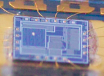
A two-dimensional photodiode array of only 4 × 4 pixels occupies the left side of the first optical mouse sensor chip, c. 1982.

A one-dimensional array of hundreds or thousands of photodiodes can be used as a position sensor, for example as part of an angle sensor. A two-dimensional array is used in image sensors and optical mice.

In some applications, photodiode arrays allow for high-speed parallel readout, as opposed to integrating scanning electronics as in a charge-coupled device (CCD) or CMOS sensor. The optical mouse chip shown in the photo has parallel (not multiplexed) access to all 16 photodiodes in its 4 × 4 array.

Passive-pixel image sensor

The passive-pixel sensor (PPS) is a type of photodiode array. It was the precursor to the active-pixel sensor (APS). A passive-pixel sensor consists of passive pixels which are read out without amplification, with each pixel consisting of a photodiode and a MOSFET switch. In a photodiode array, pixels contain a p–n junction, integrated capacitor, and MOSFETs as selection transistors. A photodiode array was proposed by G. Weckler in 1968, predating the CCD. This was the basis for the PPS.

The noise of photodiode arrays is sometimes a limitation to performance. It was not possible to fabricate active pixel sensors with a practical pixel size in the 1970s, due to limited microlithography technology at the time.

Torque

From Wikipedia, the free encyclopedia
Torque
Torque animation.gif
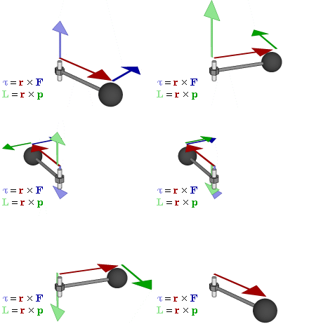
Relationship between force F, torque τ, linear momentum p, and angular momentum L in a system which has rotation constrained to only one plane (forces and moments due to gravity and friction not considered).
Common symbols
, M
SI unitN⋅m
Other units
pound-force-feet, lbf⋅inch, ozf⋅in
In SI base unitskg⋅m2⋅s−2
DimensionM L2T−2

In physics and mechanics, torque is the rotational analogue of linear force. It is also referred to as the moment of force (also abbreviated to moment). It describes the rate of change of angular momentum that would be imparted to an isolated body.

The concept originated with the studies by Archimedes of the usage of levers, which is reflected in his famous quote: "Give me a lever and a place to stand and I will move the Earth". Just as a linear force is a push or a pull applied to a body, a torque can be thought of as a twist applied to an object with respect to a chosen point. Torque is defined as the product of the magnitude of the perpendicular component of the force and the distance of the line of action of a force from the point around which it is being determined. The law of conservation of energy can also be used to understand torque. The symbol for torque is typically , the lowercase Greek letter tau. When being referred to as moment of force, it is commonly denoted by M.

In three dimensions, the torque is a pseudovector; for point particles, it is given by the cross product of the displacement vector and the force vector. The magnitude of torque applied to a rigid body depends on three quantities: the force applied, the lever arm vector connecting the point about which the torque is being measured to the point of force application, and the angle between the force and lever arm vectors. In symbols:

where

  • is the torque vector and is the magnitude of the torque,
  • is the position vector (a vector from the point about which the torque is being measured to the point where the force is applied), and r is the magnitude of the position vector,
  • is the force vector, and F is the magnitude of the force vector,
  • denotes the cross product, which produces a vector that is perpendicular both to r and to F following the right-hand rule,
  • is the angle between the force vector and the lever arm vector.

The SI unit for torque is the newton-metre (N⋅m). For more on the units of torque, see § Units.

History

The term torque (from Latin torquēre "to twist") is said to have been suggested by James Thomson and appeared in print in April, 1884. Usage is attested the same year by Silvanus P. Thompson in the first edition of Dynamo-Electric Machinery. Thompson motivates the term as follows:

Just as the Newtonian definition of force is that which produces or tends to produce motion (along a line), so torque may be defined as that which produces or tends to produce torsion (around an axis). It is better to use a term which treats this action as a single definite entity than to use terms like "couple" and "moment", which suggest more complex ideas. The single notion of a twist applied to turn a shaft is better than the more complex notion of applying a linear force (or a pair of forces) with a certain leverage.

Today, torque is referred to using different vocabulary depending on geographical location and field of study. This article follows the definition used in US physics in its usage of the word torque.

In the UK and in US mechanical engineering, torque is referred to as moment of force, usually shortened to moment. This terminology can be traced back to at least 1811 in Siméon Denis Poisson's Traité de mécanique. An English translation of Poisson's work appears in 1842.

Definition and relation to angular momentum

A particle is located at position r relative to its axis of rotation. When a force F is applied to the particle, only the perpendicular component F produces a torque. This torque τ = r × F has magnitude τ = |r| |F| = |r| |F| sin θ and is directed outward from the page.

A force applied perpendicularly to a lever multiplied by its distance from the lever's fulcrum (the length of the lever arm) is its torque. A force of three newtons applied two metres from the fulcrum, for example, exerts the same torque as a force of one newton applied six metres from the fulcrum. The direction of the torque can be determined by using the right hand grip rule: if the fingers of the right hand are curled from the direction of the lever arm to the direction of the force, then the thumb points in the direction of the torque.

More generally, the torque on a point particle (which has the position r in some reference frame) can be defined as the cross product:

where F is the force acting on the particle. The magnitude τ of the torque is given by

where F is the magnitude of the force applied, and θ is the angle between the position and force vectors. Alternatively,

where F is the amount of force directed perpendicularly to the position of the particle. Any force directed parallel to the particle's position vector does not produce a torque.

It follows from the properties of the cross product that the torque vector is perpendicular to both the position and force vectors. Conversely, the torque vector defines the plane in which the position and force vectors lie. The resulting torque vector direction is determined by the right-hand rule.

The net torque on a body determines the rate of change of the body's angular momentum,

where L is the angular momentum vector and t is time.

For the motion of a point particle,

where I is the moment of inertia and ω is the orbital angular velocity pseudovector. It follows that

where α is the angular acceleration of the particle, and p|| is the radial component of its linear momentum. This equation is the rotational analogue of Newton's second law for point particles, and is valid for any type of trajectory. Note that although force and acceleration are always parallel and directly proportional, the torque τ need not be parallel or directly proportional to the angular acceleration α. This arises from the fact that although mass is always conserved, the moment of inertia in general is not.

In some simple cases like a rotating disc, the moment of inertia is a constant, the rotational Newton's second law can be

where and .

Proof of the equivalence of definitions

The definition of angular momentum for a single point particle is:

where p is the particle's linear momentum and r is the position vector from the origin. The time-derivative of this is:

This result can easily be proven by splitting the vectors into components and applying the product rule. Now using the definition of force (whether or not mass is constant) and the definition of velocity

The cross product of momentum with its associated velocity is zero because velocity and momentum are parallel, so the second term vanishes.

By definition, torque τ = r × F. Therefore, torque on a particle is equal to the first derivative of its angular momentum with respect to time.

If multiple forces are applied, Newton's second law instead reads Fnet = ma, and it follows that

This is a general proof for point particles.

The proof can be generalized to a system of point particles by applying the above proof to each of the point particles and then summing over all the point particles. Similarly, the proof can be generalized to a continuous mass by applying the above proof to each point within the mass, and then integrating over the entire mass.

Units

Torque has the dimension of force times distance, symbolically T−2L2M. Although those fundamental dimensions are the same as that for energy or work, official SI literature suggests using the unit newton-metre (N⋅m) and never the joule. The unit newton-metre is properly denoted N⋅m.

The traditional imperial and U.S. customary units for torque are the pound foot (lbf-ft), or for small values the pound inch (lbf-in). In the US, torque is most commonly referred to as the foot-pound (denoted as either lb-ft or ft-lb) and the inch-pound (denoted as in-lb). Practitioners depend on context and the hyphen in the abbreviation to know that these refer to torque and not to energy or moment of mass (as the symbolism ft-lb would properly imply).

Special cases and other facts

Moment arm formula

Moment arm diagram

A very useful special case, often given as the definition of torque in fields other than physics, is as follows:

The construction of the "moment arm" is shown in the figure to the right, along with the vectors r and F mentioned above. The problem with this definition is that it does not give the direction of the torque but only the magnitude, and hence it is difficult to use in three-dimensional cases. If the force is perpendicular to the displacement vector r, the moment arm will be equal to the distance to the centre, and torque will be a maximum for the given force. The equation for the magnitude of a torque, arising from a perpendicular force:

For example, if a person places a force of 10 N at the terminal end of a wrench that is 0.5 m long (or a force of 10 N acting 0.5 m from the twist point of a wrench of any length), the torque will be 5 N⋅m – assuming that the person moves the wrench by applying force in the plane of movement and perpendicular to the wrench.

The torque caused by the two opposing forces Fg and −Fg causes a change in the angular momentum L in the direction of that torque. This causes the top to precess.

Static equilibrium

For an object to be in static equilibrium, not only must the sum of the forces be zero, but also the sum of the torques (moments) about any point. For a two-dimensional situation with horizontal and vertical forces, the sum of the forces requirement is two equations: ΣH = 0 and ΣV = 0, and the torque a third equation: Στ = 0. That is, to solve statically determinate equilibrium problems in two-dimensions, three equations are used.

Net force versus torque

When the net force on the system is zero, the torque measured from any point in space is the same. For example, the torque on a current-carrying loop in a uniform magnetic field is the same regardless of the point of reference. If the net force is not zero, and is the torque measured from , then the torque measured from is

Machine torque

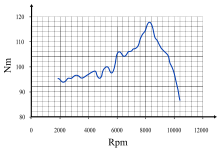
Torque curve of a motorcycle ("BMW K 1200 R 2005"). The horizontal axis shows the speed (in rpm) that the crankshaft is turning, and the vertical axis is the torque (in newton-metres) that the engine is capable of providing at that speed.

Torque forms part of the basic specification of an engine: the power output of an engine is expressed as its torque multiplied by the angular speed of the drive shaft. Internal-combustion engines produce useful torque only over a limited range of rotational speeds (typically from around 1,000–6,000 rpm for a small car). One can measure the varying torque output over that range with a dynamometer, and show it as a torque curve.

Steam engines and electric motors tend to produce maximum torque close to zero rpm, with the torque diminishing as rotational speed rises (due to increasing friction and other constraints). Reciprocating steam-engines and electric motors can start heavy loads from zero rpm without a clutch.

Relationship between torque, power, and energy

If a force is allowed to act through a distance, it is doing mechanical work. Similarly, if torque is allowed to act through an angular displacement, it is doing work. Mathematically, for rotation about a fixed axis through the center of mass, the work W can be expressed as

where τ is torque, and θ1 and θ2 represent (respectively) the initial and final angular positions of the body.

Proof

The work done by a variable force acting over a finite linear displacement is given by integrating the force with respect to an elemental linear displacement

However, the infinitesimal linear displacement is related to a corresponding angular displacement and the radius vector as

Substitution in the above expression for work gives

The expression is a scalar triple product given by . An alternate expression for the same scalar triple product is

But as per the definition of torque,

Corresponding substitution in the expression of work gives,

Since the parameter of integration has been changed from linear displacement to angular displacement, the limits of the integration also change correspondingly, giving

If the torque and the angular displacement are in the same direction, then the scalar product reduces to a product of magnitudes; i.e., giving

It follows from the work–energy principle that W also represents the change in the rotational kinetic energy Er of the body, given by

where I is the moment of inertia of the body and ω is its angular speed.

Power is the work per unit time, given by

where P is power, τ is torque, ω is the angular velocity, and represents the scalar product.

Algebraically, the equation may be rearranged to compute torque for a given angular speed and power output. Note that the power injected by the torque depends only on the instantaneous angular speed – not on whether the angular speed increases, decreases, or remains constant while the torque is being applied (this is equivalent to the linear case where the power injected by a force depends only on the instantaneous speed – not on the resulting acceleration, if any).

In practice, this relationship can be observed in bicycles: Bicycles are typically composed of two road wheels, front and rear gears (referred to as sprockets) meshing with a chain, and a derailleur mechanism if the bicycle's transmission system allows multiple gear ratios to be used (i.e. multi-speed bicycle), all of which attached to the frame. A cyclist, the person who rides the bicycle, provides the input power by turning pedals, thereby cranking the front sprocket (commonly referred to as chainring). The input power provided by the cyclist is equal to the product of angular speed (i.e. the number of pedal revolutions per minute times 2π) and the torque at the spindle of the bicycle's crankset. The bicycle's drivetrain transmits the input power to the road wheel, which in turn conveys the received power to the road as the output power of the bicycle. Depending on the gear ratio of the bicycle, a (torque, angular speed)input pair is converted to a (torque, angular speed)output pair. By using a larger rear gear, or by switching to a lower gear in multi-speed bicycles, angular speed of the road wheels is decreased while the torque is increased, product of which (i.e. power) does not change.

For SI units, the unit of power is the watt, the unit of torque is the newton-metre and the unit of angular speed is the radian per second (not rpm and not revolutions per second).

The unit newton-metre is dimensionally equivalent to the joule, which is the unit of energy. In the case of torque, the unit is assigned to a vector, whereas for energy, it is assigned to a scalar. This means that the dimensional equivalence of the newton-metre and the joule may be applied in the former, but not in the latter case. This problem is addressed in orientational analysis, which treats the radian as a base unit rather than as a dimensionless unit.

Conversion to other units

A conversion factor may be necessary when using different units of power or torque. For example, if rotational speed (unit: revolution per minute or second) is used in place of angular speed (unit: radian per second), we must multiply by 2π radians per revolution. In the following formulas, P is power, τ is torque, and ν (Greek letter nu) is rotational speed.

Showing units:

Dividing by 60 seconds per minute gives us the following.

where rotational speed is in revolutions per minute (rpm, rev/min).

Some people (e.g., American automotive engineers) use horsepower (mechanical) for power, foot-pounds (lbf⋅ft) for torque and rpm for rotational speed. This results in the formula changing to:

The constant below (in foot-pounds per minute) changes with the definition of the horsepower; for example, using metric horsepower, it becomes approximately 32,550.

The use of other units (e.g., BTU per hour for power) would require a different custom conversion factor.

Derivation

For a rotating object, the linear distance covered at the circumference of rotation is the product of the radius with the angle covered. That is: linear distance = radius × angular distance. And by definition, linear distance = linear speed × time = radius × angular speed × time.

By the definition of torque: torque = radius × force. We can rearrange this to determine force = torque ÷ radius. These two values can be substituted into the definition of power:

The radius r and time t have dropped out of the equation. However, angular speed must be in radians per unit of time, by the assumed direct relationship between linear speed and angular speed at the beginning of the derivation. If the rotational speed is measured in revolutions per unit of time, the linear speed and distance are increased proportionately by 2π in the above derivation to give:

If torque is in newton-metres and rotational speed in revolutions per second, the above equation gives power in newton-metres per second or watts. If Imperial units are used, and if torque is in pounds-force feet and rotational speed in revolutions per minute, the above equation gives power in foot pounds-force per minute. The horsepower form of the equation is then derived by applying the conversion factor 33,000 ft⋅lbf/min per horsepower:

because

Principle of moments

The principle of moments, also known as Varignon's theorem (not to be confused with the geometrical theorem of the same name) states that the resultant torques due to several forces applied to about a point is equal to the sum of the contributing torques:

From this it follows that the torques resulting from two forces acting around a pivot on an object are balanced when

Torque multiplier

Torque can be multiplied via three methods: by locating the fulcrum such that the length of a lever is increased; by using a longer lever; or by the use of a speed-reducing gearset or gear box. Such a mechanism multiplies torque, as rotation rate is reduced.

Classical radicalism

From Wikipedia, the free encyclopedia https://en.wikipedia.org/wiki/Cla...