Search This Blog

Friday, May 25, 2018

Joseph Henry

From Wikipedia, the free encyclopedia
Joseph Henry
Joseph Henry (1879).jpg

1st Secretary of the Smithsonian Institution
In office
1846–1878
Succeeded by Spencer Fullerton Baird
Personal details
Born December 17, 1797
Albany, New York, U.S.
Died May 13, 1878 (aged 80)
Washington, D.C., U.S.
Nationality American
Spouse(s) Hariet Henry (née Alexander)
Children William Alexander (1832–1862)
Mary Anna (1834–1903)
Helen Louisa (1836–1912)
Caroline (1839–1920)
Alma mater The Albany Academy
Known for Electromagnetic induction, Inventor of a precursor to the electric doorbell and electric relay

Joseph Henry (December 17, 1797 – May 13, 1878) was an American scientist who served as the first Secretary of the Smithsonian Institution. He was the secretary for the National Institute for the Promotion of Science, a precursor of the Smithsonian Institution.[1] He was highly regarded during his lifetime. While building electromagnets, Henry discovered the electromagnetic phenomenon of self-inductance. He also discovered mutual inductance independently of Michael Faraday, though Faraday was the first to make the discovery and publish his results.[2][3][4] Henry developed the electromagnet into a practical device. He invented a precursor to the electric doorbell (specifically a bell that could be rung at a distance via an electric wire, 1831)[5] and electric relay (1835).[6] The SI unit of inductance, the henry, is named in his honor. Henry's work on the electromagnetic relay was the basis of the practical electrical telegraph, invented by Samuel F. B. Morse and Sir Charles Wheatstone, separately.

Biography

Henry was born in Albany, New York, to Scottish immigrants Ann Alexander Henry and William Henry. His parents were poor, and Henry's father died while he was still young. For the rest of his childhood, Henry lived with his grandmother in Galway, New York. He attended a school which would later be named the "Joseph Henry Elementary School" in his honor. After school, he worked at a general store, and at the age of thirteen became an apprentice watchmaker and silversmith. Joseph's first love was theater and he came close to becoming a professional actor. His interest in science was sparked at the age of sixteen by a book of lectures on scientific topics titled Popular Lectures on Experimental Philosophy. In 1819 he entered The Albany Academy, where he was given free tuition. Even with free tuition he was so poor that he had to support himself with teaching and private tutoring positions. He intended to go into medicine, but in 1824 he was appointed an assistant engineer for the survey of the State road being constructed between the Hudson River and Lake Erie. From then on, he was inspired to a career in either civil or mechanical engineering.


Historical marker in Academy Park (Albany, New York) commemorating Henry's work with electricity.

Henry excelled at his studies (so much so, that he would often help his teachers teach science) and in 1826 was appointed Professor of Mathematics and Natural Philosophy at The Albany Academy by Principal T. Romeyn Beck. Some of his most important research was conducted in this new position. His curiosity about terrestrial magnetism led him to experiment with magnetism in general. He was the first to coil insulated wire tightly around an iron core in order to make a more powerful electromagnet, improving on William Sturgeon's electromagnet which used loosely coiled uninsulated wire. Using this technique, he built the strongest electromagnet at the time for Yale. He also showed that, when making an electromagnet using just two electrodes attached to a battery, it is best to wind several coils of wire in parallel, but when using a set-up with multiple batteries, there should be only one single long coil. The latter made the telegraph feasible. Because of his early experiments in electromagnetism some historians credit Henry with discoveries pre-dating Faraday and Hertz, however, Henry is not credited due to not publishing his work.[7]


Joseph Henry, taken between 1865 and 1878, possibly by Mathew Brady.

Using his newly developed electromagnetic principle, Henry in 1831 created one of the first machines to use electromagnetism for motion. This was the earliest ancestor of modern DC motor. It did not make use of rotating motion, but was merely an electromagnet perched on a pole, rocking back and forth. The rocking motion was caused by one of the two leads on both ends of the magnet rocker touching one of the two battery cells, causing a polarity change, and rocking the opposite direction until the other two leads hit the other battery.

This apparatus allowed Henry to recognize the property of self inductance. British scientist Michael Faraday also recognized this property around the same time. Since Faraday published his results first, he became the officially recognized discoverer of the phenomenon.

From 1832 to 1846, Henry served as the first Chair of Natural History at the College of New Jersey (now Princeton University).[8][9] While in Princeton, he taught a wide range of courses including natural history, chemistry, and architecture, and ran a laboratory on campus. Decades later, Henry wrote that he made "several thousand original investigations on electricity, magnetism, and electro-magnetism" while on the Princeton faculty.[10] Henry relied heavily on an African American research assistant, Sam Parker, in his laboratory and experiments. Parker was a free black man hired by the Princeton trustees to assist Henry. In an 1841 letter to mathematician Elias Loomis, Henry wrote:
The Trustees have however furnished me with an article which I now find indispensible namely with a coloured servant whom I have taught to manage my batteries and who now relieves me from all the dirty work of the laboratory.[11]
In his letters, Henry described Parker providing materials for experiments, fixing technical issues with Henry's equipment, and at times being used as a test subject in electrical experiments in which Henry and his students would shock Parker in classroom demonstrations.[8][9] In 1842, when Parker fell ill, Henry's experiments stopped completely until he recovered.[8][9]

Henry was appointed the first Secretary of the Smithsonian Institution in 1846, and served in this capacity until 1878. In 1848, while Secretary, Henry worked in conjunction with Professor Stephen Alexander to determine the relative temperatures for different parts of the solar disk. They used a thermopile to determine that sunspots were cooler than the surrounding regions.[12][13][14][15] This work was shown to the astronomer Angelo Secchi who extended it, but with some question as to whether Henry was given proper credit for his earlier work.[16]

In late 1861 and early 1862, during the American Civil War, Henry oversaw a series of lectures by prominent abolitionists at the Smithsonian Institution.[17] Speakers included white clergymen, politicians, and activists such as Wendell Phillips, Horace Greeley, Henry Ward Beecher, and Ralph Waldo Emerson. Famous orator and former fugitive slave Frederick Douglass was scheduled as the final speaker; Henry, however, refused to allow him to attend, stating: "I would not let the lecture of the coloured man be given in the rooms of the Smithsonian."[8][17]

In the fall of 2014 history author Jeremy T.K. Farley released "The Civil War Out My Window: Diary of Mary Henry." The 262-page book featured the diary of Henry's daughter Mary, from the years of 1855 to 1878. Throughout the diary, Henry is repeatedly mentioned by his daughter, who showed a keen affection to her father.[18]

Influences in aeronautics

Prof. Henry was introduced to Prof. Thaddeus Lowe, a balloonist from New Hampshire who had taken interest in the phenomenon of lighter-than-air gases, and exploits into meteorology, in particular, the high winds which we call the Jet stream today. It was Lowe's intent to make a transatlantic crossing by utilizing an enormous gas-inflated aerostat. Henry took a great interest in Lowe's endeavors, promoting him among some of the more prominent scientists and institutions of the day.

In June 1860, Lowe had made a successful test flight with his gigantic balloon, first named the City of New York and later renamed The Great Western, flying from Philadelphia to Medford, New York. Lowe would not be able to attempt a transatlantic flight until late Spring of the 1861, so Henry convinced him to take his balloon to a point more West and fly the balloon back to the eastern seaboard, an exercise that would keep his investors interested.

Lowe took several smaller balloons to Cincinnati, Ohio in March 1861. On 19 April, he launched on a fateful flight that landed him in Confederate South Carolina. With the Southern States seceding from the Union, during that winter and spring of 1861, and the onset of Civil War, Lowe abandoned further attempts at a trans-Atlantic crossing and, with Henry's endorsement, went to Washington, D.C. to offer his services as an aeronaut to the Federal government. Henry submitted a letter to U.S. Secretary of War at the time Simon Cameron of Pennsylvania which carried Henry's endorsement:
Hon. SIMON CAMERON

DEAR SIR: In accordance with your request made to me orally on the morning of the 6th of June, I have examined the apparatus and witnessed the balloon experiments of Mr. Lowe, and have come to the following conclusions

1st. The balloon prepared by Mr. Lowe, inflated with ordinary street gas, will retain its charge for several days.

2d. In an inflated condition it can be towed by a few men along an ordinary road, or over fields, in ordinarily calm weather, from the places where it is galled [i.e. swelled or inflated] to another, twenty or more miles distant.

3d. It can be let up into the air by means of a rope in a calm day to a height sufficient to observe the country for twenty miles around and more, according to the degree of clearness of the atmosphere. The ascent may also be made at night and the camp lights of the enemy observed.

4th. From experiments made here for the first time it is conclusively proved that telegrams can be sent with ease and certainty between the balloon and the quarters of the commanding officer.

5th. I feel assured, although I have not witnessed the experiment, that when the surface wind is from the east, as it was for several days last week, an observer in the balloon can be made to float nearly to the enemy's camp (as it is now situated to the west of us), or even to float over it, and then return eastward by rising to a higher elevation. This assumption is based on the fact that the upper strata of wind in this latitude is always flowing eastward. Mr. Lowe informs me, and I do not doubt his statement, that he will on any day which is favorable make an excursion of the kind above mentioned.

6th. From all the facts I have observed and the information I have gathered I am sure that important information may be obtained in regard to the topography of the country and to the position and movements of an enemy by means of the balloon now, and that Mr. Lowe is well qualified to render service in this way by the balloon now in his possession.

7th. The balloon which Mr. Lowe now has in Washington can only be inflated in a city where street gas is to be obtained. If an exploration is required at a point too distant for the transportation of the inflated balloon, an additional apparatus for the generation of hydrogen gas will be required. The necessity of generating the gas renders the use of the balloon more expensive, but this, where important results are required, is of comparatively small importance.

For these preliminary experiments, as you may recollect, a sum not to exceed $200 or $250 was to be appropriated, and in accordance with this Mr. Lowe has presented me with the in closed statement of items, which I think are reasonable, since nothing is charged for labor and time of the aeronautic.

I have the honor to remain, very respectfully, your obedient servant,
JOSEPH HENRY,
Secretary Smithsonian Institution.
On Henry's recommendation Lowe went on to form the United States Army/"Union Army" Balloon Corps and served two years with the Army of the Potomac as a Civil War "Aeronaut".

Later years


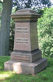
Henry's grave, Oak Hill Cemetery, Washington, D.C.

As a famous scientist and director of the Smithsonian Institution, Henry received visits from other scientists and inventors who sought his advice. Henry was patient, kindly, self-controlled, and gently humorous.[19] One such visitor was Alexander Graham Bell, who on 1 March 1875 carried a letter of introduction to Henry. Henry showed an interest in seeing Bell's experimental apparatus, and Bell returned the following day. After the demonstration, Bell mentioned his untested theory on how to transmit human speech electrically by means of a "harp apparatus" which would have several steel reeds tuned to different frequencies to cover the voice spectrum. Henry said Bell had "the germ of a great invention". Henry advised Bell not to publish his ideas until he had perfected the invention. When Bell objected that he lacked the necessary knowledge, Henry firmly advised: "Get it!"

On 25 June 1876, Bell's experimental telephone (using a different design) was demonstrated at the Centennial Exhibition in Philadelphia where Henry was one of the judges for electrical exhibits. On 13 January 1877, Bell demonstrated his instruments to Henry at the Smithsonian Institution and Henry invited Bell to demonstrate them again that night at the Washington Philosophical Society. Henry praised "the value and astonishing character of Mr. Bell's discovery and invention."[20]

Henry died on 13 May 1878, and was buried in Oak Hill Cemetery in the Georgetown section of northwest Washington, D.C. John Phillips Sousa wrote the Transit of Venus March for the unveiling of the Joseph Henry statue in front of the Smithsonian Castle.

Legacy

Henry was a member of the United States Lighthouse Board from 1852 until his death. He was appointed chairman in 1871 and served in that position the remainder of his life. He was the only civilian to serve as chairman. The United States Coast Guard honored Henry for his work on lighthouses and fog signal acoustics by naming a cutter after him. The Joseph Henry, usually referred to as the Joe Henry, was launched in 1880 and was active until 1904.[21]

In 1915 Henry was inducted into the Hall of Fame for Great Americans in the Bronx, New York.

Bronze statues of Henry and Isaac Newton represent science on the balustrade of the galleries of the Main Reading Room in the Thomas Jefferson Building of the Library of Congress on Capitol Hill in Washington, D.C. They are two of the 16 historical figures depicted in the reading room, each pair representing one of the 8 pillars of civilization.

In 1872 John Wesley Powell named a mountain range in southeastern Utah after Henry. The Henry Mountains were the last mountain range to be added to the map of the 48 contiguous U.S. states.

At Princeton, the Joseph Henry Laboratories and the Joseph Henry House are named for him.[22]

After the Albany Academy moved out of its downtown building in the early 1930s, its old building in Academy Park was renamed Joseph Henry Memorial, with a statue of him out front. It is now the main offices of the Albany City School District. In 1971 it was listed on the National Register of Historic Places; later it was included as a contributing property when the Lafayette Park Historic District was listed on the Register.

Curriculum vitae


Statue of Henry before Smithsonian Institution

Other honors

Elected a member of the American Antiquarian Society in 1851.[23]

The District of Columbia named a school, built in 1878–80, on P Street between 6th and 7th the Joseph Henry School. It was demolished at some point after 1932.

The Henry Mountains (Utah) had been so named by geologist Almon Thompson in his honour.

Faraday's law of induction

From Wikipedia, the free encyclopedia
Faraday's law of induction is a basic law of electromagnetism predicting how a magnetic field will interact with an electric circuit to produce an electromotive force (EMF)—a phenomenon called electromagnetic induction. It is the fundamental operating principle of transformers, inductors, and many types of electrical motors, generators and solenoids.[1][2]

The Maxwell–Faraday equation is a generalization of Faraday's law, and is listed as one of Maxwell's equations.

History

A diagram of Faraday's iron ring apparatus. The changing magnetic flux of the left coil induces a current in the right coil.[3]
 
Faraday's disk, the first electric generator, a type of homopolar generator.

Electromagnetic induction was discovered independently by Michael Faraday in 1831 and Joseph Henry in 1832.[4] Faraday was the first to publish the results of his experiments.[5][6] In Faraday's first experimental demonstration of electromagnetic induction (August 29, 1831),[7] he wrapped two wires around opposite sides of an iron ring (torus) (an arrangement similar to a modern toroidal transformer). Based on his assessment of recently discovered properties of electromagnets, he expected that when current started to flow in one wire, a sort of wave would travel through the ring and cause some electrical effect on the opposite side. He plugged one wire into a galvanometer, and watched it as he connected the other wire to a battery. Indeed, he saw a transient current (which he called a "wave of electricity") when he connected the wire to the battery, and another when he disconnected it.[8] This induction was due to the change in magnetic flux that occurred when the battery was connected and disconnected.[3] Within two months, Faraday had found several other manifestations of electromagnetic induction. For example, he saw transient currents when he quickly slid a bar magnet in and out of a coil of wires, and he generated a steady (DC) current by rotating a copper disk near the bar magnet with a sliding electrical lead ("Faraday's disk").[9]

Michael Faraday explained electromagnetic induction using a concept he called lines of force. However, scientists at the time widely rejected his theoretical ideas, mainly because they were not formulated mathematically.[10] An exception was James Clerk Maxwell, who in 1861-2 used Faraday's ideas as the basis of his quantitative electromagnetic theory.[10][11][12] In Maxwell's papers, the time-varying aspect of electromagnetic induction is expressed as a differential equation which Oliver Heaviside referred to as Faraday's law even though it is different from the original version of Faraday's law, and does not describe motional EMF. Heaviside's version (see Maxwell–Faraday equation below) is the form recognized today in the group of equations known as Maxwell's equations.

Lenz's law, formulated by Emil Lenz in 1834,[13] describes "flux through the circuit", and gives the direction of the induced EMF and current resulting from electromagnetic induction (elaborated upon in the examples below).

Faraday's experiment showing induction between coils of wire: The liquid battery (right) provides a current which flows through the small coil (A), creating a magnetic field. When the coils are stationary, no current is induced. But when the small coil is moved in or out of the large coil (B), the magnetic flux through the large coil changes, inducing a current which is detected by the galvanometer (G).[14]

Faraday's law

Qualitative statement

The most widespread version of Faraday's law states:
The induced electromotive force in any closed circuit is equal to the negative of the time rate of change of the magnetic flux enclosed by the circuit.[15][16]
This version of Faraday's law strictly holds only when the closed circuit is a loop of infinitely thin wire,[17] and is invalid in other circumstances as discussed below. A different version, the Maxwell–Faraday equation (discussed below), is valid in all circumstances.

Quantitative

The definition of surface integral relies on splitting the surface Σ into small surface elements. Each element is associated with a vector dA of magnitude equal to the area of the element and with direction normal to the element and pointing "outward" (with respect to the orientation of the surface).

Faraday's law of induction makes use of the magnetic flux ΦB through a hypothetical surface Σ whose boundary is a wire loop. Since the wire loop may be moving, we write Σ(t) for the surface. The magnetic flux is defined by a surface integral:
{\displaystyle \Phi _{B}=\iint \limits _{\Sigma (t)}\mathbf {B} (\mathbf {r} ,t)\cdot d\mathbf {A} \,,}
where dA is an element of surface area of the moving surface Σ(t), B is the magnetic field (also called "magnetic flux density"), and B·dA is a vector dot product (the infinitesimal amount of magnetic flux through the infinitesimal area element dA). In more visual terms, the magnetic flux through the wire loop is proportional to the number of magnetic flux lines that pass through the loop.

When the flux changes—because B changes, or because the wire loop is moved or deformed, or both—Faraday's law of induction says that the wire loop acquires an EMF, , defined as the energy available from a unit charge that has travelled once around the wire loop.[17][18][19][20] Equivalently, it is the voltage that would be measured by cutting the wire to create an open circuit, and attaching a voltmeter to the leads.

Faraday's law states that the EMF is also given by the rate of change of the magnetic flux:
{\displaystyle {\mathcal {E}}=-{\frac {d\Phi _{B}}{dt}},}
where {\mathcal {E}} is the electromotive force (EMF) and ΦB is the magnetic flux.

The direction of the electromotive force is given by Lenz's law.

The laws of induction of electric currents in mathematical form was established by Franz Ernst Neumann in 1845.[21]

Faraday's law contains the information about the relationships between both the magnitudes and the directions of its variables. However, the relationships between the directions are not explicit; they are hidden in the mathematical formula.

A Left Hand Rule for Faraday’s Law.
The sign of ΔΦB, the change in flux, is found based on the relationship between the magnetic field B, the area of the loop A, and the normal n to that area, as represented by the fingers of the left hand. If ΔΦB is positive, the direction of the EMF is the same as that of the curved fingers (yellow arrowheads). If ΔΦB is negative, the direction of the EMF is against the arrowheads.[22]

It is possible to find out the direction of the electromotive force (EMF) directly from Faraday’s law, without invoking Lenz's law. A left hand rule helps doing that, as follows:[22][23]
  • Align the curved fingers of the left hand with the loop (yellow line).
  • Stretch your thumb. The stretched thumb indicates the direction of n (brown), the normal to the area enclosed by the loop.
  • Find the sign of ΔΦB, the change in flux. Determine the initial and final fluxes (whose difference is ΔΦB) with respect to the normal n, as indicated by the stretched thumb.
  • If the change in flux, ΔΦB, is positive, the curved fingers show the direction of the electromotive force (yellow arrowheads).
  • If ΔΦB is negative, the direction of the electromotive force is opposite to the direction of the curved fingers (opposite to the yellow arrowheads).
For a tightly wound coil of wire, composed of N identical turns, each with the same ΦB, Faraday's law of induction states that[24][25]
{\displaystyle {\mathcal {E}}=-N{\frac {d\Phi _{B}}{dt}}}
where N is the number of turns of wire and ΦB is the magnetic flux through a single loop.

Maxwell–Faraday equation

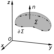
An illustration of the Kelvin–Stokes theorem with surface Σ, its boundary Σ, and orientation n set by the right-hand rule.

The Maxwell–Faraday equation is a modification and generalisation of Faraday's law that states that a time-varying magnetic field will always accompany a spatially varying, non-conservative electric field, and vice versa. The Maxwell–Faraday equation is
\nabla \times \mathbf {E} =-{\frac {\partial \mathbf {B} }{\partial t}}
(in SI units) where ∇ × is the curl operator and again E(r, t) is the electric field and B(r, t) is the magnetic field. These fields can generally be functions of position r and time t.

The Maxwell–Faraday equation is one of the four Maxwell's equations, and therefore plays a fundamental role in the theory of classical electromagnetism. It can also be written in an integral form by the Kelvin–Stokes theorem:[26]
{\displaystyle \oint _{\partial \Sigma }\mathbf {E} \cdot d\mathbf {l} =-\int _{\Sigma }{\frac {\partial \mathbf {B} }{\partial t}}\cdot d\mathbf {A} }
where, as indicated in the figure:
Σ is a surface bounded by the closed contour Σ,
E is the electric field, B is the magnetic field.
dl is an infinitesimal vector element of the contour ∂Σ,
dA is an infinitesimal vector element of surface Σ. If its direction is orthogonal to that surface patch, the magnitude is the area of an infinitesimal patch of surface.
Both dl and dA have a sign ambiguity; to get the correct sign, the right-hand rule is used, as explained in the article Kelvin–Stokes theorem. For a planar surface Σ, a positive path element dl of curve Σ is defined by the right-hand rule as one that points with the fingers of the right hand when the thumb points in the direction of the normal n to the surface Σ.

The integral around Σ is called a path integral or line integral.

Notice that a nonzero path integral for E is different from the behavior of the electric field generated by charges. A charge-generated E-field can be expressed as the gradient of a scalar field that is a solution to Poisson's equation, and has a zero path integral. See gradient theorem.

The integral equation is true for any path Σ through space, and any surface Σ for which that path is a boundary.

If the surface Σ is not changing in time, the equation can be rewritten:
{\displaystyle \oint _{\partial \Sigma }\mathbf {E} \cdot d\mathbf {l} =-{\frac {d}{dt}}\int _{\Sigma }\mathbf {B} \cdot d\mathbf {A} .}
The surface integral at the right-hand side is the explicit expression for the magnetic flux ΦB through Σ.

Proof of Faraday's law

The four Maxwell's equations (including the Maxwell–Faraday equation), along with the Lorentz force law, are a sufficient foundation to derive everything in classical electromagnetism.[17][18] Therefore, it is possible to "prove" Faraday's law starting with these equations.[27][28]

The starting point is the time-derivative of flux through an arbitrary, possibly moving surface in space Σ:
{\frac {d\Phi _{B}}{dt}}={\frac {d}{dt}}\int _{\Sigma (t)}\mathbf {B} (t)\cdot d\mathbf {A}
(by definition). This total time derivative can be evaluated and simplified with the help of the Maxwell–Faraday equation, Gauss's law for magnetism, and some vector calculus.  The result is:
{\displaystyle {\frac {d\Phi _{B}}{dt}}=-\oint _{\partial \Sigma }\left(\mathbf {E} +\mathbf {v} _{\mathbf {l} }\times \mathbf {B} \right)\cdot d\mathbf {l} .}
where ∂Σ is the boundary of the surface Σ, and vl is the velocity of that boundary.

While this equation is true for any arbitrary moving surface Σ in space, it can be simplified further in the special case that ∂Σ is a loop of wire. In this case, we can relate the right-hand-side to EMF. Specifically, EMF is defined as the energy available per unit charge that travels once around the loop. Therefore, by the Lorentz force law,
{\displaystyle {\mathcal {E}}=\oint \left(\mathbf {E} +\mathbf {v} _{m}\times \mathbf {B} \right)\cdot {\text{d}}\mathbf {l} }
where {\mathcal {E}} is EMF and vm is the material velocity, i.e. the velocity of the atoms that makes up the circuit. If ∂Σ is a loop of wire, then vm=vl, and hence:
{\displaystyle {\frac {d\Phi _{B}}{dt}}=-{\mathcal {E}}}

EMF for non-thin-wire circuits

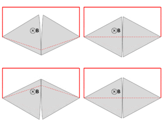
It is tempting to generalize Faraday's law to state that If ∂Σ is any arbitrary closed loop in space whatsoever, then the total time derivative of magnetic flux through Σ equals the EMF around ∂Σ. This statement, however, is not always true—and not just for the obvious reason that EMF is undefined in empty space when no conductor is present. As noted in the previous section, Faraday's law is not guaranteed to work unless the velocity of the abstract curve ∂Σ matches the actual velocity of the material conducting the electricity.[30] The two examples illustrated below show that one often obtains incorrect results when the motion of ∂Σ is divorced from the motion of the material.[17]
One can analyze examples like these by taking care that the path ∂Σ moves with the same velocity as the material.[30] Alternatively, one can always correctly calculate the EMF by combining the Lorentz force law with the Maxwell–Faraday equation:[17][31]
{\displaystyle {\mathcal {E}}=\int _{\partial \Sigma }(\mathbf {E} +\mathbf {v} _{m}\times \mathbf {B} )\cdot d\mathbf {l} =-\int _{\Sigma }{\frac {\partial \mathbf {B} }{\partial t}}\cdot d\mathbf {\Sigma } +\oint _{\partial \Sigma }(\mathbf {v} _{m}\times \mathbf {B} )\cdot d\mathbf {l} }
where "it is very important to notice that (1) [vm] is the velocity of the conductor ... not the velocity of the path element dl and (2) in general, the partial derivative with respect to time cannot be moved outside the integral since the area is a function of time".[31]

Faraday's law and relativity

Two phenomena

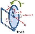
Faraday's law is a single equation describing two different phenomena: the motional EMF generated by a magnetic force on a moving wire (see Lorentz force), and the transformer EMF generated by an electric force due to a changing magnetic field (due to the Maxwell–Faraday equation).

James Clerk Maxwell drew attention to this fact in his 1861 paper On Physical Lines of Force.[32] In the latter half of Part II of that paper, Maxwell gives a separate physical explanation for each of the two phenomena.

A reference to these two aspects of electromagnetic induction is made in some modern textbooks.[33] As Richard Feynman states:[17]
So the "flux rule" that the emf in a circuit is equal to the rate of change of the magnetic flux through the circuit applies whether the flux changes because the field changes or because the circuit moves (or both) ...

Yet in our explanation of the rule we have used two completely distinct laws for the two cases – v × B for "circuit moves" and ∇ × E = −∂tB for "field changes".

We know of no other place in physics where such a simple and accurate general principle requires for its real understanding an analysis in terms of two different phenomena.

— Richard P. Feynman, The Feynman Lectures on Physics

Einstein's view

Reflection on this apparent dichotomy was one of the principal paths that led Einstein to develop special relativity:
It is known that Maxwell's electrodynamics—as usually understood at the present time—when applied to moving bodies, leads to asymmetries which do not appear to be inherent in the phenomena. Take, for example, the reciprocal electrodynamic action of a magnet and a conductor.

The observable phenomenon here depends only on the relative motion of the conductor and the magnet, whereas the customary view draws a sharp distinction between the two cases in which either the one or the other of these bodies is in motion. For if the magnet is in motion and the conductor at rest, there arises in the neighbourhood of the magnet an electric field with a certain definite energy, producing a current at the places where parts of the conductor are situated.

But if the magnet is stationary and the conductor in motion, no electric field arises in the neighbourhood of the magnet. In the conductor, however, we find an electromotive force, to which in itself there is no corresponding energy, but which gives rise—assuming equality of relative motion in the two cases discussed—to electric currents of the same path and intensity as those produced by the electric forces in the former case.

Examples of this sort, together with unsuccessful attempts to discover any motion of the earth relative to the "light medium," suggest that the phenomena of electrodynamics as well as of mechanics possess no properties corresponding to the idea of absolute rest.

Thermoelectric generator

From Wikipedia, the free encyclopedia
 
A thermoelectric generator (TEG), also called a Seebeck generator, is a solid state device that converts heat flux (temperature differences) directly into electrical energy through a phenomenon called the Seebeck effect (a form of thermoelectric effect). Thermoelectric generators function like heat engines, but are less bulky and have no moving parts. However, TEGs are typically more expensive and less efficient.[1]

Thermoelectric generators could be used in power plants in order to convert waste heat into additional electrical power and in automobiles as automotive thermoelectric generators (ATGs) to increase fuel efficiency. Another application is radioisotope thermoelectric generators which are used in space probes, which has the same mechanism but use radioisotopes to generate the required heat difference.[1]

History

In 1821, Thomas Johann Seebeck discovered that a thermal gradient formed between two dissimilar conductors can produce electricity.[2] At the heart of the thermoelectric effect is the fact that a temperature gradient in a conducting material results in heat flow; this results in the diffusion of charge carriers. The flow of charge carriers between the hot and cold regions in turn creates a voltage difference. In 1834, Jean Charles Athanase Peltier discovered the reverse effect, that running an electric current through the junction of two dissimilar conductors could, depending on the direction of the current, cause it to act as a heater or cooler.[3]

Construction

Thermoelectric power generators consist of three major components: thermoelectric materials, thermoelectric modules and thermoelectric systems that interface with the heat source.[4]

Thermoelectric materials

Thermoelectric materials generate power directly from heat by converting temperature differences into electric voltage. These materials must have both high electrical conductivity (σ) and low thermal conductivity (κ) to be good thermoelectric materials. Having low thermal conductivity ensures that when one side is made hot, the other side stays cold, which helps to generate a large voltage while in a temperature gradient. The measure of the magnitude of electrons flow in response to a temperature difference across that material is given by the Seebeck coefficient (S). The efficiency of a given material to produce a thermoelectric power is governed by its “figure of merit” zT = S2σT/κ.

For many years, the main three semiconductors known to have both low thermal conductivity and high power factor were bismuth telluride (Bi2Te3), lead telluride (PbTe), and silicon germanium (SiGe). These materials have very rare elements which make them very expensive compounds.

Today, the thermal conductivity of semiconductors can be lowered without affecting their high electrical properties using nanotechnology. This can be achieved by creating nanoscale features such as particles, wires or interfaces in bulk semiconductor materials. However, the manufacturing processes of nano-materials is still challenging.

A thermoelectric circuit composed of materials of different Seebeck coefficient (p-doped and n-doped semiconductors), configured as a thermoelectric generator.

Thermoelectric module

A thermoelectric module is a circuit containing thermoelectric materials which generates electricity from heat directly. A thermoelectric module consists of two dissimilar thermoelectric materials joined at their ends: an n-type (negatively charged); and a p-type (positively charged) semiconductors. A direct electric current will flow in the circuit when there is a temperature difference between the two materials. Generally, the current magnitude is directly proportional to the temperature difference.[citation needed]

In application, thermoelectric modules in power generation work in very tough mechanical and thermal conditions. Because they operate in very high temperature gradient, the modules are subject to large thermally induced stresses and strains for long periods of time. They also are subject to mechanical fatigue caused by large number of thermal cycles.

Thus, the junctions and materials must be selected so that they survive these tough mechanical and thermal conditions. Also, the module must be designed such that the two thermoelectric materials are thermally in parallel, but electrically in series. The efficiency of a thermoelectric module is greatly affected by the geometry of its design.

Thermoelectric system

Using thermoelectric modules, a thermoelectric system generates power by taking in heat from a source such as a hot exhaust flue. In order to do that, the system needs a large temperature gradient, which is not easy in real-world applications. The cold side must be cooled by air or water. Heat exchangers are used on both sides of the modules to supply this heating and cooling.

There are many challenges in designing a reliable TEG system that operates at high temperatures. Achieving high efficiency in the system requires extensive engineering design in order to balance between the heat flow through the modules and maximizing the temperature gradient across them. To do this, designing heat exchanger technologies in the system is one of the most important aspects of TEG engineering. In addition, the system requires to minimize the thermal losses due to the interfaces between materials at several places. Another challenging constraint is avoiding large pressure drops between the heating and cooling sources.

After the DC power from the TE modules passes through an inverter, the TEG produces AC power, which in turn, requires an integrated power electronics system to deliver it to the customer.

Materials for TEG

Only a few known materials to date are identified as thermoelectric materials. Most thermoelectric materials today have a zT, the figure of merit, value of around 1, such as in Bismuth Telluride (Bi2Te3) at room temperature and lead telluride (PbTe) at 500-700K. However, in order to be competitive with other power generation systems, TEG materials should have a zT of 2-3. Most research in thermoelectric materials has focused on increasing the Seebeck coefficient (S) and reducing the thermal conductivity, especially by manipulating the nanostructure of the thermoelectric materials. Because the thermal and electrical conductivity correlate with the charge carriers, new means must be introduced in order to conciliate the contradiction between high electrical conductivity and low thermal conductivity as indicated.[5]

When selecting materials for thermoelectric generation, a number of other factors need to be considered. During operation, ideally the thermoelectric generator has a large temperature gradient across it. Thermal expansion will then introduce stress in the device which may cause fracture of the thermoelectric legs, or separation from the coupling material. The mechanical properties of the materials must be considered and the coefficient of thermal expansion of the n and p-type material must be matched reasonably well. In segmented thermoelectric generators, the material's compatibility must also be considered. A material's compatibility factor is defined as
{\displaystyle s=\left({\frac {{\sqrt {1-zT}}-1}{ST}}\right)}.[6] When the compatibility factor from one segment to the next differs by more than a factor of about two, the device will not operate efficiently. The material parameters determining s (as well as zT) are temperature dependent, so the compatibility factor may change from the hot side to the cold side of the device, even in one segment. This behavior is referred to as self-compatibility and may become important in devices design for low temperature operation.

In general, thermoelectric materials can be categorized into conventional and new materials:

Conventional materials

There are many TEG materials that are employed in commercial applications today. These materials can be divided into three groups based on the temperature range of operation:
  1. Low temperature materials (up to around 450K): Alloys based on Bismuth (Bi) in combinations with Antimony (Sb), Tellurium (Te) or Selenium (Se).
  2. Intermediate temperature (up to 850K): such as materials based on alloys of Lead (Pb)
  3. Highest temperatures material (up to 1300K): materials fabricated from silicon germanium (SiGe) alloys.
Although these materials still remain the cornerstone for commercial and practical applications in thermoelectric power generation, significant advances have been made in synthesizing new materials and fabricating material structures with improved thermoelectric performance. Recent research have focused on improving the material’s figure-of-merit (zT), and hence the conversion efficiency, by reducing the lattice thermal conductivity.[5]

New materials

Researchers are trying to develop new thermoelectric materials for power generation by improving the figure-of-merit zT. One example of these materials is the semiconductor compound ß-Zn4Sb3, which possesses an exceptionally low thermal conductivity and exhibits a maximum zT of 1.3 at a temperature of 670K. This material is also relatively inexpensive and stable up to this temperature in a vacuum, and can be a good alternative in the temperature range between materials based on Bi2Te3 and PbTe.[5]

Beside improving the figure-of-merit, there is increasing focus to develop new materials by increasing the electrical power output, decreasing cost and developing environmentally friendly materials. For example, when the fuel cost is low or almost free, such as in waste heat recovery, then the cost per watt is only determined by the power per unit area and the operating period. As a result, it has initiated a search for materials with high power output rather than conversion efficiency. For example, the rare earth compounds YbAl3 has a low figure-of-merit, but it has a power output of at least double that of any other material, and can operate over the temperature range of a waste heat source.[5]

Novel Processing

In order to increase the figure of merit (zT), a material’s thermal conductivity should be minimized while its electrical conductivity and Seebeck coefficient is maximized. In most cases, methods to increase or decrease one property result in the same effect on other properties due to their interdependence.[7] A novel processing technique exploits the scattering of different phonon frequencies to selectively reduce lattice thermal conductivity without the typical negative effects on electrical conductivity from the simultaneous increased scattering of electrons. In a bismuth antimony tellurium ternary system, liquid-phase sintering is used to produce low-energy semicoherent grain boundaries, which do not have a significant scattering effect on electrons.[8] The breakthrough is then applying a pressure to the liquid in the sintering process, which creates a transient flow of the Te rich liquid and facilitates the formation of dislocations that greatly reduce the lattice conductivity.[8] The ability to selectively decrease the lattice conductivity results in reported zT values of 1.86 ± .15 which are a significant improvement over current commercial thermoelectric generators which have typical figures of merit closer to .3-.6.[9] These improvements highlight the fact that in addition to development of novel materials for thermoelectric applications, using different processing techniques to design microstructure is a viable and worthwhile effort. In fact, it often makes sense to work to optimize both composition and microstructure.[10]

Efficiency

The typical efficiency of TEGs is around 5–8%. Older devices used bimetallic junctions and were bulky. More recent devices use highly doped semiconductors made from bismuth telluride (Bi2Te3), lead telluride (PbTe),[11] calcium manganese oxide (Ca2Mn3O8),[12][13] or combinations thereof,[14] depending on temperature. These are solid-state devices and unlike dynamos have no moving parts, with the occasional exception of a fan or pump.

Uses

Thermoelectric generators have a variety of applications. Frequently, thermoelectric generators are used for low power remote applications or where bulkier but more efficient heat engines such as Stirling engines would not be possible. Unlike heat engines, the solid state electrical components typically used to perform thermal to electric energy conversion have no moving parts. The thermal to electric energy conversion can be performed using components that require no maintenance, have inherently high reliability, and can be used to construct generators with long service-free lifetimes. This makes thermoelectric generators well suited for equipment with low to modest power needs in remote uninhabited or inaccessible locations such as mountaintops, the vacuum of space, or the deep ocean.
  • Common application is the use of thermoelectric generators on gas pipelines. For example, for cathodic protection, radio communication, and other telemetry. On gas pipelines for power consumption of up to 5 kW thermal generators are preferable to other power sources. The manufacturers of generators for gas pipelines are Gentherm Global Power Technologies (Formerly Global Thermoelectric), (Calgary, Canada) and TELGEN (Russia).
  • Thermoelectric Generators are primarily used as remote and off-grid power generators for unmanned sites. They are the most reliable power generator in such situations as they do not have moving parts (thus virtually maintenance free), work day and night, perform under all weather conditions, and can work without battery backup. Although Solar Photovoltaic systems are also implemented in remote sites, Solar PV may not be a suitable solution where solar radiation is low, i.e. areas at higher latitudes with snow or no sunshine, areas with lots of cloud or tree canopy cover, dusty deserts, forests, etc.
  • Gentherm Global Power Technologies (GPT) formerly known as Global Thermoelectric (Canada) has Hybrid Solar-TEG solutions where the Thermoelectric Generator backs up the Solar-PV, such that if the Solar panel is down and the backup battery backup goes into deep discharge then a sensor starts the TEG as a backup power source until the Solar is up again. The TEG heat can be produced by a low pressure flame fueled by Propane or Natural Gas.
  • Many space probes, including the Mars Curiosity rover, generate electricity using a radioisotope thermoelectric generator whose heat source is a radioactive element.
  • Cars and other automobiles produce waste heat (in the exhaust and in the cooling agents). Harvesting that heat energy, using a thermoelectric generator, can increase the fuel efficiency of the car. For more details, see the article: Automotive thermoelectric generator.
  • In addition to automobiles, waste heat is also generated in many other places, such as in industrial processes and in heating (wood stoves, outdoor boilers, cooking, oil and gas fields, pipelines, and remote communication towers).
  • Microprocessors generate waste heat. Researchers have considered whether some of that energy could be recycled.[15] (However, see below for problems that can arise.)
  • Solar cells use only the high frequency part of the radiation, while the low frequency heat energy is wasted. Several patents about the use of thermoelectric devices in tandem with solar cells have been filed.[16] The idea is to increase the efficiency of the combined solar/thermoelectric system to convert the solar radiation into useful electricity.
  • The Maritime Applied Physics Corporation in Baltimore, Maryland [17] is developing a thermoelectric generator to produce electric power on the deep-ocean offshore seabed using the temperature difference between cold seawater and hot fluids released by hydrothermal vents, hot seeps, or from drilled geothermal wells. A high reliability source of seafloor electric power is needed for ocean observatories and sensors used in the geological, environmental, and ocean sciences, by seafloor mineral and energy resource developers, and by the military.
  • Ann Makosinski from British Columbia, Canada has developed several devices using Peltier tiles to harvest heat (from a human hand,[18] the forehead, and hot beverage[19]) that claims to generate enough electricity to power an LED light or charge a mobile device, although the inventor admits that the brightness of the LED light is not competitive with those on the market.[20]

Practical limitations

Besides low efficiency and relatively high cost, practical problems exist in using thermoelectric devices in certain types of applications resulting from a relatively high electrical output resistance, which increases self-heating, and a relatively low thermal conductivity, which makes them unsuitable for applications where heat removal is critical, as with heat removal from an electrical device such as microprocessors.
  • High generator output resistance: In order to get voltage output levels in the range required by digital electrical devices, a common approach is to place many thermoelectric elements in series within a generator module. The element's voltages add, but so do their individual output resistance. The maximum power transfer theorem dictates that maximum power is delivered to a load when the source and load resistances are identically matched. For low impedance loads near zero ohms, as the generator resistance rises the power delivered to the load decreases. To lower the output resistance, some commercial devices place more individual elements in parallel and fewer in series and employ a boost regulator to raise the voltage to the voltage needed by the load.
  • Low thermal conductivity: Because a very high thermal conductivity is required to transport thermal energy away from a heat source such as a digital microprocessor, the low thermal conductivity of thermoelectric generators makes them unsuitable to recover the heat.
  • Cold-side heat removal with air: In air-cooled thermoelectric applications, such as when harvesting thermal energy from a motor vehicle's crankcase, the large amount of thermal energy that must be dissipated into ambient air presents a significant challenge. As a thermoelectric generator's cool side temperature rises, the device's differential working temperature decreases. As the temperature rises, the device's electrical resistance increases causing greater parasitic generator self-heating. In motor vehicle applications a supplementary radiator is sometimes used for improved heat removal, though the use of an electric water pump to circulate a coolant adds an additional parasitic loss to total generator output power. Water cooling the thermoelectric generator's cold side, as when generating thermoelectric power from the hot crank case of an inboard boat motor, would not suffer from this disadvantage. Water is a far easier coolant to use effectively in contrast to air.

Future market

While TEG technology has been used in military and aerospace applications for decades, new TE materials and systems are being developed to generate power using low or high temperatures waste heat, and that could provide a significant opportunity in the near future. These systems can also be scalable to any size and have lower operation and maintenance cost.

In general, investing in TEG technology is increasing rapidly. The global market for thermoelectric generators is estimated to be US$320 million in 2015. A recent study estimated that TEG is expected to reach $720 million in 2021 with a growth rate of 14.5%. Today, North America capture 66% of the market share and it will continue to be the biggest market in the near future.[21] However, Asia-Pacific and European countries are projected to grow at relatively higher rates. A study found that the Asia-Pacific market would grow at a Compound Annual Growth Rate (CAGR) of 18.3% in the period from 2015 to 2020 due to the high demand of thermoelectric generators by the automotive industries to increase overall fuel efficiency, as well as the growing industrialization in the region.[22]

Low power TEG or "sub-watt" (i.e. generating up to 1 Watt peak) market is a growing part of the TEG market, capitalizing on latest technologies. Main applications are sensors, low power applications and more globally Internet of things applications. A specialized market research company indicated that 100 000 units have been shipped in 2014 and expects 9 million units per year by 2020.[23]

Butane

From Wikipedia, the free encyclopedia ...