Faraday's law of induction is a basic law of electromagnetism predicting how a magnetic field will interact with an electric circuit to produce an electromotive force (EMF)—a phenomenon called electromagnetic induction. It is the fundamental operating principle of transformers, inductors, and many types of electrical motors, generators and solenoids.[1][2]
The Maxwell–Faraday equation is a generalization of Faraday's law, and is listed as one of Maxwell's equations.
The Maxwell–Faraday equation is a generalization of Faraday's law, and is listed as one of Maxwell's equations.
History
A diagram of Faraday's iron ring apparatus. The changing magnetic flux of the left coil induces a current in the right coil.[3]
Faraday's disk, the first electric generator, a type of homopolar generator.
Electromagnetic induction was discovered independently by Michael Faraday in 1831 and Joseph Henry in 1832.[4] Faraday was the first to publish the results of his experiments.[5][6] In Faraday's first experimental demonstration of electromagnetic induction (August 29, 1831),[7] he wrapped two wires around opposite sides of an iron ring (torus) (an arrangement similar to a modern toroidal transformer). Based on his assessment of recently discovered properties of electromagnets, he expected that when current started to flow in one wire, a sort of wave would travel through the ring and cause some electrical effect on the opposite side. He plugged one wire into a galvanometer, and watched it as he connected the other wire to a battery. Indeed, he saw a transient current (which he called a "wave of electricity") when he connected the wire to the battery, and another when he disconnected it.[8] This induction was due to the change in magnetic flux that occurred when the battery was connected and disconnected.[3] Within two months, Faraday had found several other manifestations of electromagnetic induction. For example, he saw transient currents when he quickly slid a bar magnet in and out of a coil of wires, and he generated a steady (DC) current by rotating a copper disk near the bar magnet with a sliding electrical lead ("Faraday's disk").[9]
Michael Faraday explained electromagnetic induction using a concept he called lines of force. However, scientists at the time widely rejected his theoretical ideas, mainly because they were not formulated mathematically.[10] An exception was James Clerk Maxwell, who in 1861-2 used Faraday's ideas as the basis of his quantitative electromagnetic theory.[10][11][12] In Maxwell's papers, the time-varying aspect of electromagnetic induction is expressed as a differential equation which Oliver Heaviside referred to as Faraday's law even though it is different from the original version of Faraday's law, and does not describe motional EMF. Heaviside's version (see Maxwell–Faraday equation below) is the form recognized today in the group of equations known as Maxwell's equations.
Lenz's law, formulated by Emil Lenz in 1834,[13] describes "flux through the circuit", and gives the direction of the induced EMF and current resulting from electromagnetic induction (elaborated upon in the examples below).
Faraday's experiment showing induction between coils of wire: The liquid battery (right) provides a current which flows through the small coil (A),
creating a magnetic field. When the coils are stationary, no current is
induced. But when the small coil is moved in or out of the large coil (B), the magnetic flux through the large coil changes, inducing a current which is detected by the galvanometer (G).[14]
Faraday's law
Qualitative statement
The most widespread version of Faraday's law states:The induced electromotive force in any closed circuit is equal to the negative of the time rate of change of the magnetic flux enclosed by the circuit.[15][16]This version of Faraday's law strictly holds only when the closed circuit is a loop of infinitely thin wire,[17] and is invalid in other circumstances as discussed below. A different version, the Maxwell–Faraday equation (discussed below), is valid in all circumstances.
Quantitative
The definition of surface integral relies on splitting the surface Σ into small surface elements. Each element is associated with a vector dA
of magnitude equal to the area of the element and with direction normal
to the element and pointing "outward" (with respect to the orientation
of the surface).
Faraday's law of induction makes use of the magnetic flux ΦB through a hypothetical surface Σ whose boundary is a wire loop. Since the wire loop may be moving, we write Σ(t) for the surface. The magnetic flux is defined by a surface integral:
When the flux changes—because B changes, or because the wire loop is moved or deformed, or both—Faraday's law of induction says that the wire loop acquires an EMF, ℰ, defined as the energy available from a unit charge that has travelled once around the wire loop.[17][18][19][20] Equivalently, it is the voltage that would be measured by cutting the wire to create an open circuit, and attaching a voltmeter to the leads.
Faraday's law states that the EMF is also given by the rate of change of the magnetic flux:
 is the electromotive force (EMF) and ΦB is the magnetic flux.
The direction of the electromotive force is given by Lenz's law.
The laws of induction of electric currents in mathematical form was established by Franz Ernst Neumann in 1845.[21]
Faraday's law contains the information about the relationships between both the magnitudes and the directions of its variables. However, the relationships between the directions are not explicit; they are hidden in the mathematical formula.
A Left Hand Rule for Faraday’s Law.
The sign of ΔΦB, the change in flux, is found based on the relationship between the magnetic field B, the area of the loop A, and the normal n to that area, as represented by the fingers of the left hand. If ΔΦB is positive, the direction of the EMF is the same as that of the curved fingers (yellow arrowheads). If ΔΦB is negative, the direction of the EMF is against the arrowheads.[22]
The sign of ΔΦB, the change in flux, is found based on the relationship between the magnetic field B, the area of the loop A, and the normal n to that area, as represented by the fingers of the left hand. If ΔΦB is positive, the direction of the EMF is the same as that of the curved fingers (yellow arrowheads). If ΔΦB is negative, the direction of the EMF is against the arrowheads.[22]
It is possible to find out the direction of the electromotive force (EMF) directly from Faraday’s law, without invoking Lenz's law. A left hand rule helps doing that, as follows:[22][23]
- Align the curved fingers of the left hand with the loop (yellow line).
- Stretch your thumb. The stretched thumb indicates the direction of n (brown), the normal to the area enclosed by the loop.
- Find the sign of ΔΦB, the change in flux. Determine the initial and final fluxes (whose difference is ΔΦB) with respect to the normal n, as indicated by the stretched thumb.
- If the change in flux, ΔΦB, is positive, the curved fingers show the direction of the electromotive force (yellow arrowheads).
- If ΔΦB is negative, the direction of the electromotive force is opposite to the direction of the curved fingers (opposite to the yellow arrowheads).
Maxwell–Faraday equation
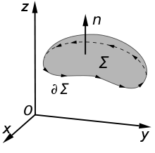
An illustration of the Kelvin–Stokes theorem with surface Σ, its boundary ∂Σ, and orientation n set by the right-hand rule.
The Maxwell–Faraday equation is a modification and generalisation of Faraday's law that states that a time-varying magnetic field will always accompany a spatially varying, non-conservative electric field, and vice versa. The Maxwell–Faraday equation is
The Maxwell–Faraday equation is one of the four Maxwell's equations, and therefore plays a fundamental role in the theory of classical electromagnetism. It can also be written in an integral form by the Kelvin–Stokes theorem:[26]
- Σ is a surface bounded by the closed contour ∂Σ,
- E is the electric field, B is the magnetic field.
- dl is an infinitesimal vector element of the contour ∂Σ,
- dA is an infinitesimal vector element of surface Σ. If its direction is orthogonal to that surface patch, the magnitude is the area of an infinitesimal patch of surface.
The integral around ∂Σ is called a path integral or line integral.
Notice that a nonzero path integral for E is different from the behavior of the electric field generated by charges. A charge-generated E-field can be expressed as the gradient of a scalar field that is a solution to Poisson's equation, and has a zero path integral. See gradient theorem.
The integral equation is true for any path ∂Σ through space, and any surface Σ for which that path is a boundary.
If the surface Σ is not changing in time, the equation can be rewritten:
Proof of Faraday's law
The four Maxwell's equations (including the Maxwell–Faraday equation), along with the Lorentz force law, are a sufficient foundation to derive everything in classical electromagnetism.[17][18] Therefore, it is possible to "prove" Faraday's law starting with these equations.[27][28]The starting point is the time-derivative of flux through an arbitrary, possibly moving surface in space Σ:
While this equation is true for any arbitrary moving surface Σ in space, it can be simplified further in the special case that ∂Σ is a loop of wire. In this case, we can relate the right-hand-side to EMF. Specifically, EMF is defined as the energy available per unit charge that travels once around the loop. Therefore, by the Lorentz force law,
 is EMF and vm is the material velocity, i.e. the velocity of the atoms that makes up the circuit. If ∂Σ is a loop of wire, then vm=vl, and hence:
EMF for non-thin-wire circuits
It is tempting to generalize Faraday's law to state that If ∂Σ is any arbitrary closed loop in space whatsoever, then the total time derivative of magnetic flux through Σ equals the EMF around ∂Σ. This statement, however, is not always true—and not just for the obvious reason that EMF is undefined in empty space when no conductor is present. As noted in the previous section, Faraday's law is not guaranteed to work unless the velocity of the abstract curve ∂Σ matches the actual velocity of the material conducting the electricity.[30] The two examples illustrated below show that one often obtains incorrect results when the motion of ∂Σ is divorced from the motion of the material.[17]-
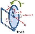
Faraday's homopolar generator. The disc rotates with angular rate ω, sweeping the conducting radius circularly in the static magnetic field B. The magnetic Lorentz force v × B drives the current along the conducting radius to the conducting rim, and from there the circuit completes through the lower brush and the axle supporting the disc. This device generates an EMF and a current, although the shape of the "circuit" is constant and thus the flux through the circuit does not change with time.
-
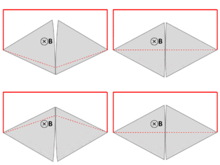
A wire (solid red lines) connects to two touching metal plates (silver) to form a circuit. The whole system sits in a uniform magnetic field, normal to the page. If the abstract path ∂Σ follows the primary path of current flow (marked in red), then the magnetic flux through this path changes dramatically as the plates are rotated, yet the EMF is almost zero. After Feynman Lectures on Physics Vol. II page 17-3.
Faraday's law and relativity
Two phenomena
Faraday's law is a single equation describing two different phenomena: the motional EMF generated by a magnetic force on a moving wire (see Lorentz force), and the transformer EMF generated by an electric force due to a changing magnetic field (due to the Maxwell–Faraday equation).James Clerk Maxwell drew attention to this fact in his 1861 paper On Physical Lines of Force.[32] In the latter half of Part II of that paper, Maxwell gives a separate physical explanation for each of the two phenomena.
A reference to these two aspects of electromagnetic induction is made in some modern textbooks.[33] As Richard Feynman states:[17]
So the "flux rule" that the emf in a circuit is equal to the rate of change of the magnetic flux through the circuit applies whether the flux changes because the field changes or because the circuit moves (or both) ...
Yet in our explanation of the rule we have used two completely distinct laws for the two cases – v × B for "circuit moves" and ∇ × E = −∂tB for "field changes".
We know of no other place in physics where such a simple and accurate general principle requires for its real understanding an analysis in terms of two different phenomena.
— Richard P. Feynman, The Feynman Lectures on Physics
Einstein's view
Reflection on this apparent dichotomy was one of the principal paths that led Einstein to develop special relativity:It is known that Maxwell's electrodynamics—as usually understood at the present time—when applied to moving bodies, leads to asymmetries which do not appear to be inherent in the phenomena. Take, for example, the reciprocal electrodynamic action of a magnet and a conductor.
The observable phenomenon here depends only on the relative motion of the conductor and the magnet, whereas the customary view draws a sharp distinction between the two cases in which either the one or the other of these bodies is in motion. For if the magnet is in motion and the conductor at rest, there arises in the neighbourhood of the magnet an electric field with a certain definite energy, producing a current at the places where parts of the conductor are situated.
But if the magnet is stationary and the conductor in motion, no electric field arises in the neighbourhood of the magnet. In the conductor, however, we find an electromotive force, to which in itself there is no corresponding energy, but which gives rise—assuming equality of relative motion in the two cases discussed—to electric currents of the same path and intensity as those produced by the electric forces in the former case.
Examples of this sort, together with unsuccessful attempts to discover any motion of the earth relative to the "light medium," suggest that the phenomena of electrodynamics as well as of mechanics possess no properties corresponding to the idea of absolute rest.


