Search This Blog

Monday, February 18, 2019

Optical microscope

From Wikipedia, the free encyclopedia

Microscope
UsesSmall sample observation
Notable experimentsDiscovery of cells
Related itemsMicroscope
Electron microscope
Scanning probe microscope
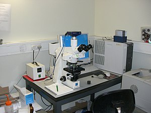
A modern microscope with a mercury bulb for fluorescence microscopy. The microscope has a digital camera, and is attached to a computer.
 
The optical microscope, often referred to as the light microscope, is a type of microscope that commonly uses visible light and a system of lenses to magnify images of small objects. Optical microscopes are the oldest design of microscope and were possibly invented in their present compound form in the 17th century. Basic optical microscopes can be very simple, although many complex designs aim to improve resolution and sample contrast. Often used in the classroom and at home unlike the electron microscope which is used for closer viewing. 

The image from an optical microscope can be captured by normal, photosensitive cameras to generate a micrograph. Originally images were captured by photographic film, but modern developments in CMOS and charge-coupled device (CCD) cameras allow the capture of digital images. Purely digital microscopes are now available which use a CCD camera to examine a sample, showing the resulting image directly on a computer screen without the need for eyepieces.

Alternatives to optical microscopy which do not use visible light include scanning electron microscopy and transmission electron microscopy and scanning probe microscopy.

On 8 October 2014, the Nobel Prize in Chemistry was awarded to Eric Betzig, William Moerner and Stefan Hell for "the development of super-resolved fluorescence microscopy," which brings "optical microscopy into the nanodimension".

Types

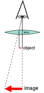
Diagram of a simple microscope
 
There are two basic types of optical microscopes: simple microscopes and compound microscopes. A simple microscope is one which uses a single lens for magnification, such as a magnifying glass. A compound microscope uses several lenses to enhance the magnification of an object. The vast majority of modern research microscopes are compound microscopes while some cheaper commercial digital microscopes are simple single lens microscopes. Compound microscopes can be further divided into a variety of other types of microscopes which differ in their optical configurations, cost, and intended purposes.

Regular microscope

A regular microscope uses a lens or set of lenses to enlarge an object through angular magnification alone, giving the viewer an erect enlarged virtual image. The use of a single convex lens or groups of lenses are found in simple magnification devices such as the magnifying glass, loupes, and eyepieces for telescopes and microscopes.

Compound microscope

Diagram of a compound microscope
 
A compound microscope uses a lens close to the object being viewed to collect light (called the objective lens) which focuses a real image of the object inside the microscope (image 1). That image is then magnified by a second lens or group of lenses (called the eyepiece) that gives the viewer an enlarged inverted virtual image of the object (image 2). The use of a compound objective/eyepiece combination allows for much higher magnification. Common compound microscopes often feature exchangeable objective lenses, allowing the user to quickly adjust the magnification. A compound microscope also enables more advanced illumination setups, such as phase contrast.

Other microscope variants

There are many variants of the compound optical microscope design for specialized purposes. Some of these are physical design differences allowing specialization for certain purposes:
  • Stereo microscope, a low-powered microscope which provides a stereoscopic view of the sample, commonly used for dissection.
  • Comparison microscope, which has two separate light paths allowing direct comparison of two samples via one image in each eye.
  • Inverted microscope, for studying samples from below; useful for cell cultures in liquid, or for metallography.
  • Fiber optic connector inspection microscope, designed for connector end-face inspection
  • Traveling microscope, for studying samples of high optical resolution.
Other microscope variants are designed for different illumination techniques:
  • Petrographic microscope, whose design usually includes a polarizing filter, rotating stage and gypsum plate to facilitate the study of minerals or other crystalline materials whose optical properties can vary with orientation.
  • Polarizing microscope, similar to the petrographic microscope.
  • Phase contrast microscope, which applies the phase contrast illumination method.
  • Epifluorescence microscope, designed for analysis of samples which include fluorophores.
  • Confocal microscope, a widely used variant of epifluorescent illumination which uses a scanning laser to illuminate a sample for fluorescence.
  • Two-photon microscope, used to image fluorescence deeper in scattering media and reduce photobleaching, especially in living samples.
  • Student microscope – an often low-power microscope with simplified controls and sometimes low quality optics designed for school use or as a starter instrument for children.
  • Ultramicroscope, an adapted light microscope that uses light scattering to allow viewing of tiny particles whose diameter is below or near the wavelength of visible light (around 500 nanometers); mostly obsolete since the advent of electron microscopes

Digital microscope

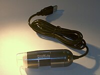
A miniature USB microscope.

A digital microscope is a microscope equipped with a digital camera allowing observation of a sample via a computer. Microscopes can also be partly or wholly computer-controlled with various levels of automation. Digital microscopy allows greater analysis of a microscope image, for example measurements of distances and areas and quantitaton of a fluorescent or histological stain.

Low-powered digital microscopes, USB microscopes, are also commercially available. These are essentially webcams with a high-powered macro lens and generally do not use transillumination. The camera attached directly to the USB port of a computer, so that the images are shown directly on the monitor. They offer modest magnifications (up to about 200×) without the need to use eyepieces, and at very low cost. High power illumination is usually provided by an LED source or sources adjacent to the camera lens. 

Digital microscopy with very low light levels to avoid damage to vulnerable biological samples is available using sensitive photon-counting digital cameras. It has been demonstrated that a light source providing pairs of entangled photons may minimize the risk of damage to the most light-sensitive samples. In this application of ghost imaging to photon-sparse microscopy, the sample is illuminated with infrared photons, each of which is spatially correlated with an entangled partner in the visible band for efficient imaging by a photon-counting camera.

History

Invention

The earliest microscopes were single lens magnifying glasses with limited magnification which date at least as far back as the widespread use of lenses in eyeglasses in the 13th century.

Compound microscopes first appeared in Europe around 1620 including one demonstrated by Cornelis Drebbel in London (around 1621) and one exhibited in Rome in 1624.

The actual inventor of the compound microscope is unknown although many claims have been made over the years. These include a claim 35 years after they appeared by Dutch spectacle-maker Johannes Zachariassen that his father, Zacharias Janssen, invented the compound microscope and/or the telescope as early as 1590. Johannes' (some claim dubious) testimony pushes the invention date so far back that Zacharias would have been a child at the time, leading to speculation that, for Johannes' claim to be true, the compound microscope would have to have been invented by Johannes' grandfather, Hans Martens. Another claim is that Janssen's competitor, Hans Lippershey (who applied for the first telescope patent in 1608) also invented the compound microscope. Other historians point to the Dutch innovator Cornelis Drebbel with his 1621 compound microscope.

Galileo Galilei is also sometimes cited as a compound microscope inventor. After 1610 he found that he could close focus his telescope to view small objects, such as flies, close up and/or could look through the wrong end in reverse to magnify small objects. The only drawback was that his 2 foot long telescope had to be extended out to 6 feet to view objects that close. After seeing the compound microscope built by Drebbel exhibited in Rome in 1624, Galileo built his own improved version. In 1625 Giovanni Faber coined the name microscope for the compound microscope Galileo submitted to the Accademia dei Lincei in 1624 (Galileo had called it the "occhiolino" or "little eye"). Faber coined the name from the Greek words μικρόν (micron) meaning "small", and σκοπεῖν (skopein) meaning "to look at", a name meant to be analogous with "telescope", another word coined by the Linceans.

Christiaan Huygens, another Dutchman, developed a simple 2-lens ocular system in the late 17th century that was achromatically corrected, and therefore a huge step forward in microscope development. The Huygens ocular is still being produced to this day, but suffers from a small field size, and other minor disadvantages.

Popularization

The oldest published image known to have been made with a microscope: bees by Francesco Stelluti, 1630
 
Antonie van Leeuwenhoek (1632–1724) is credited with bringing the microscope to the attention of biologists, even though simple magnifying lenses were already being produced in the 16th century. Van Leeuwenhoek's home-made microscopes were simple microscopes, with a single very small, yet strong lens. They were awkward in use, but enabled van Leeuwenhoek to see detailed images. It took about 150 years of optical development before the compound microscope was able to provide the same quality image as van Leeuwenhoek's simple microscopes, due to difficulties in configuring multiple lenses. In the 1850s John Leonard Riddell, Professor of Chemistry at Tulane University, invented the first practical binocular microscope while carrying out one of the earliest and most extensive American microscopic investigations of cholera.

Lighting techniques

While basic microscope technology and optics have been available for over 400 years it is much more recently that techniques in sample illumination were developed to generate the high quality images seen today. 

In August 1893 August Köhler developed Köhler illumination. This method of sample illumination gives rise to extremely even lighting and overcomes many limitations of older techniques of sample illumination. Before development of Köhler illumination the image of the light source, for example a lightbulb filament, was always visible in the image of the sample.

The Nobel Prize in physics was awarded to Dutch physicist Frits Zernike in 1953 for his development of phase contrast illumination which allows imaging of transparent samples. By using interference rather than absorption of light, extremely transparent samples, such as live mammalian cells, can be imaged without having to use staining techniques. Just two years later, in 1955, Georges Nomarski published the theory for differential interference contrast microscopy, another interference-based imaging technique.

Fluorescence microscopy

Modern biological microscopy depends heavily on the development of fluorescent probes for specific structures within a cell. In contrast to normal trans-illuminated light microscopy, in fluorescence microscopy the sample is illuminated through the objective lens with a narrow set of wavelengths of light. This light interacts with fluorophores in the sample which then emit light of a longer wavelength. It is this emitted light which makes up the image.

Since the mid 20th century chemical fluorescent stains, such as DAPI which binds to DNA, have been used to label specific structures within the cell. More recent developments include immunofluorescence, which uses fluorescently labelled antibodies to recognize specific proteins within a sample, and fluorescent proteins like GFP which a live cell can express making it fluorescent.

Components

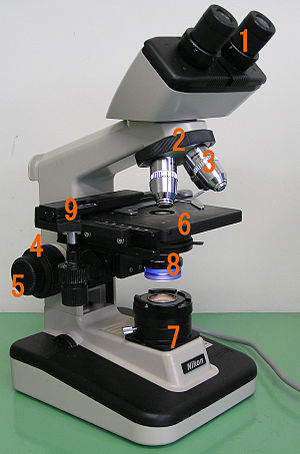
Basic optical transmission microscope elements (1990s)
 
All modern optical microscopes designed for viewing samples by transmitted light share the same basic components of the light path. In addition, the vast majority of microscopes have the same 'structural' components (numbered below according to the image on the right):
  • Eyepiece (ocular lens) (1)
  • Objective turret, revolver, or revolving nose piece (to hold multiple objective lenses) (2)
  • Objective lenses (3)
  • Focus knobs (to move the stage)
    • Coarse adjustment (4)
    • Fine adjustment (5)
  • Stage (to hold the specimen) (6)
  • Light source (a light or a mirror) (7)
  • Diaphragm and condenser (8)
  • Mechanical stage (9)

Eyepiece (ocular lens)

The eyepiece, or ocular lens, is a cylinder containing two or more lenses; its function is to bring the image into focus for the eye. The eyepiece is inserted into the top end of the body tube. Eyepieces are interchangeable and many different eyepieces can be inserted with different degrees of magnification. Typical magnification values for eyepieces include 5×, 10× (the most common), 15× and 20×. In some high performance microscopes, the optical configuration of the objective lens and eyepiece are matched to give the best possible optical performance. This occurs most commonly with apochromatic objectives.

Objective turret (revolver or revolving nose piece)

Objective turret, revolver, or revolving nose piece is the part that holds the set of objective lenses. It allows the user to switch between objective lenses.

Objective

At the lower end of a typical compound optical microscope, there are one or more objective lenses that collect light from the sample. The objective is usually in a cylinder housing containing a glass single or multi-element compound lens. Typically there will be around three objective lenses screwed into a circular nose piece which may be rotated to select the required objective lens. These arrangements are designed to be parfocal, which means that when one changes from one lens to another on a microscope, the sample stays in focus. Microscope objectives are characterized by two parameters, namely, magnification and numerical aperture. The former typically ranges from 5× to 100× while the latter ranges from 0.14 to 0.7, corresponding to focal lengths of about 40 to 2 mm, respectively. Objective lenses with higher magnifications normally have a higher numerical aperture and a shorter depth of field in the resulting image. Some high performance objective lenses may require matched eyepieces to deliver the best optical performance.

Oil immersion objective

Two Leica oil immersion microscope objective lenses: 100× (left) and 40× (right)

Some microscopes make use of oil-immersion objectives or water-immersion objectives for greater resolution at high magnification. These are used with index-matching material such as immersion oil or water and a matched cover slip between the objective lens and the sample. The refractive index of the index-matching material is higher than air allowing the objective lens to have a larger numerical aperture (greater than 1) so that the light is transmitted from the specimen to the outer face of the objective lens with minimal refraction. Numerical apertures as high as 1.6 can be achieved. The larger numerical aperture allows collection of more light making detailed observation of smaller details possible. An oil immersion lens usually has a magnification of 40 to 100×.

Focus knobs

Adjustment knobs move the stage up and down with separate adjustment for coarse and fine focusing. The same controls enable the microscope to adjust to specimens of different thickness. In older designs of microscopes, the focus adjustment wheels move the microscope tube up or down relative to the stand and had a fixed stage.

Frame

The whole of the optical assembly is traditionally attached to a rigid arm, which in turn is attached to a robust U-shaped foot to provide the necessary rigidity. The arm angle may be adjustable to allow the viewing angle to be adjusted. 

The frame provides a mounting point for various microscope controls. Normally this will include controls for focusing, typically a large knurled wheel to adjust coarse focus, together with a smaller knurled wheel to control fine focus. Other features may be lamp controls and/or controls for adjusting the condenser.

Stage

The stage is a platform below the objective which supports the specimen being viewed. In the center of the stage is a hole through which light passes to illuminate the specimen. The stage usually has arms to hold slides (rectangular glass plates with typical dimensions of 25×75 mm, on which the specimen is mounted). 

At magnifications higher than 100× moving a slide by hand is not practical. A mechanical stage, typical of medium and higher priced microscopes, allows tiny movements of the slide via control knobs that reposition the sample/slide as desired. If a microscope did not originally have a mechanical stage it may be possible to add one. 

All stages move up and down for focus. With a mechanical stage slides move on two horizontal axes for positioning the specimen to examine specimen details.

Focusing starts at lower magnification in order to center the specimen by the user on the stage. Moving to a higher magnification requires the stage to be moved higher vertically for re-focus at the higher magnification and may also require slight horizontal specimen position adjustment. Horizontal specimen position adjustments are the reason for having a mechanical stage. 

Due to the difficulty in preparing specimens and mounting them on slides, for children it's best to begin with prepared slides that are centered and focus easily regardless of the focus level used.

Light source

Many sources of light can be used. At its simplest, daylight is directed via a mirror. Most microscopes, however, have their own adjustable and controllable light source – often a halogen lamp, although illumination using LEDs and lasers are becoming a more common provision. Köhler illumination is often provided on more expensive instruments.

Condenser

The condenser is a lens designed to focus light from the illumination source onto the sample. The condenser may also include other features, such as a diaphragm and/or filters, to manage the quality and intensity of the illumination. For illumination techniques like dark field, phase contrast and differential interference contrast microscopy additional optical components must be precisely aligned in the light path.

Magnification

The actual power or magnification of a compound optical microscope is the product of the powers of the ocular (eyepiece) and the objective lens. The maximum normal magnifications of the ocular and objective are 10× and 100× respectively, giving a final magnification of 1,000×.

Magnification and micrographs

When using a camera to capture a micrograph the effective magnification of the image must take into account the size of the image. This is independent of whether it is on a print from a film negative or displayed digitally on a computer screen

In the case of photographic film cameras the calculation is simple; the final magnification is the product of: the objective lens magnification, the camera optics magnification and the enlargement factor of the film print relative to the negative. A typical value of the enlargement factor is around 5× (for the case of 35 mm film and a 15 × 10 cm (6 × 4 inch) print). 

In the case of digital cameras the size of the pixels in the CMOS or CCD detector and the size of the pixels on the screen have to be known. The enlargement factor from the detector to the pixels on screen can then be calculated. As with a film camera the final magnification is the product of: the objective lens magnification, the camera optics magnification and the enlargement factor.

Operation

Illumination techniques

Many techniques are available which modify the light path to generate an improved contrast image from a sample. Major techniques for generating increased contrast from the sample include cross-polarized light, dark field, phase contrast and differential interference contrast illumination. A recent technique (Sarfus) combines cross-polarized light and specific contrast-enhanced slides for the visualization of nanometric samples.

Other techniques

Modern microscopes allow more than just observation of transmitted light image of a sample; there are many techniques which can be used to extract other kinds of data. Most of these require additional equipment in addition to a basic compound microscope.
  • Reflected light, or incident, illumination (for analysis of surface structures)
  • Fluorescence microscopy, both:
  • Microspectroscopy (where a UV-visible spectrophotometer is integrated with an optical microscope)
  • Ultraviolet microscopy
  • Near-Infrared microscopy
  • Multiple transmission microscopy for contrast enhancement and aberration reduction.
  • Automation (for automatic scanning of a large sample or image capture)

Applications

A 40x magnification image of cells in a medical smear test taken through an optical microscope using a wet mount technique, placing the specimen on a glass slide and mixing with a salt solution
 
Optical microscopy is used extensively in microelectronics, nanophysics, biotechnology, pharmaceutic research, mineralogy and microbiology.

Optical microscopy is used for medical diagnosis, the field being termed histopathology when dealing with tissues, or in smear tests on free cells or tissue fragments.

In industrial use, binocular microscopes are common. Aside from applications needing true depth perception, the use of dual eyepieces reduces eye strain associated with long workdays at a microscopy station. In certain applications, long-working-distance or long-focus microscopes are beneficial. An item may need to be examined behind a window, or industrial subjects may be a hazard to the objective. Such optics resemble telescopes with close-focus capabilities.

Measuring microscopes are used for precision measurement. There are two basic types. One has a reticle graduated to allow measuring distances in the focal plane. The other (and older) type has simple crosshairs and a micrometer mechanism for moving the subject relative to the microscope.

Limitations

At very high magnifications with transmitted light, point objects are seen as fuzzy discs surrounded by diffraction rings. These are called Airy disks. The resolving power of a microscope is taken as the ability to distinguish between two closely spaced Airy disks (or, in other words the ability of the microscope to reveal adjacent structural detail as distinct and separate). It is these impacts of diffraction that limit the ability to resolve fine details. The extent and magnitude of the diffraction patterns are affected by both the wavelength of light (λ), the refractive materials used to manufacture the objective lens and the numerical aperture (NA) of the objective lens. There is therefore a finite limit beyond which it is impossible to resolve separate points in the objective field, known as the diffraction limit. Assuming that optical aberrations in the whole optical set-up are negligible, the resolution d, can be stated as:
Usually a wavelength of 550 nm is assumed, which corresponds to green light. With air as the external medium, the highest practical NA is 0.95, and with oil, up to 1.5. In practice the lowest value of d obtainable with conventional lenses is about 200 nm. A new type of lens using multiple scattering of light allowed to improve the resolution to below 100 nm.

Surpassing the resolution limit

Multiple techniques are available for reaching resolutions higher than the transmitted light limit described above. Holographic techniques, as described by Courjon and Bulabois in 1979, are also capable of breaking this resolution limit, although resolution was restricted in their experimental analysis.

Using fluorescent samples more techniques are available. Examples include Vertico SMI, near field scanning optical microscopy which uses evanescent waves, and stimulated emission depletion. In 2005, a microscope capable of detecting a single molecule was described as a teaching tool.

Despite significant progress in the last decade, techniques for surpassing the diffraction limit remain limited and specialized.

While most techniques focus on increases in lateral resolution there are also some techniques which aim to allow analysis of extremely thin samples. For example, sarfus methods place the thin sample on a contrast-enhancing surface and thereby allows to directly visualize films as thin as 0.3 nanometers.

Structured illumination SMI

SMI (spatially modulated illumination microscopy) is a light optical process of the so-called point spread function (PSF) engineering. These are processes which modify the PSF of a microscope in a suitable manner to either increase the optical resolution, to maximize the precision of distance measurements of fluorescent objects that are small relative to the wavelength of the illuminating light, or to extract other structural parameters in the nanometer range.

Localization microscopy SPDMphymod

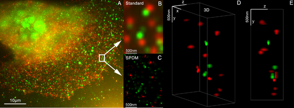
3D dual color super resolution microscopy with Her2 and Her3 in breast cells, standard dyes: Alexa 488, Alexa 568 LIMON
 
SPDM (spectral precision distance microscopy), the basic localization microscopy technology is a light optical process of fluorescence microscopy which allows position, distance and angle measurements on "optically isolated" particles (e.g. molecules) well below the theoretical limit of resolution for light microscopy. "Optically isolated" means that at a given point in time, only a single particle/molecule within a region of a size determined by conventional optical resolution (typically approx. 200–250 nm diameter) is being registered. This is possible when molecules within such a region all carry different spectral markers (e.g. different colors or other usable differences in the light emission of different particles).

Many standard fluorescent dyes like GFP, Alexa dyes, Atto dyes, Cy2/Cy3 and fluorescein molecules can be used for localization microscopy, provided certain photo-physical conditions are present. Using this so-called SPDMphymod (physically modifiable fluorophores) technology a single laser wavelength of suitable intensity is sufficient for nanoimaging.

3D super resolution microscopy

3D super resolution microscopy with standard fluorescent dyes can be achieved by combination of localization microscopy for standard fluorescent dyes SPDMphymod and structured illumination SMI.

STED

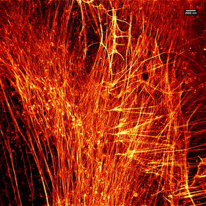
Stimulated emission depletion (STED) microscopy image of actin filaments within a cell.
 
Stimulated emission depletion is a simple example of how higher resolution surpassing the diffraction limit is possible, but it has major limitations. STED is a fluorescence microscopy technique which uses a combination of light pulses to induce fluorescence in a small sub-population of fluorescent molecules in a sample. Each molecule produces a diffraction-limited spot of light in the image, and the centre of each of these spots corresponds to the location of the molecule. As the number of fluorescing molecules is low the spots of light are unlikely to overlap and therefore can be placed accurately. This process is then repeated many times to generate the image. Stefan Hell of the Max Planck Institute for Biophysical Chemistry was awarded the 10th German Future Prize in 2006 and Nobel Prize for Chemistry in 2014 for his development of the STED microscope and associated methodologies.

Alternatives

In order to overcome the limitations set by the diffraction limit of visible light other microscopes have been designed which use other waves.
It is important to note that higher frequency waves have limited interaction with matter, for example soft tissues are relatively transparent to X-rays resulting in distinct sources of contrast and different target applications. 

The use of electrons and X-rays in place of light allows much higher resolution – the wavelength of the radiation is shorter so the diffraction limit is lower. To make the short-wavelength probe non-destructive, the atomic beam imaging system (atomic nanoscope) has been proposed and widely discussed in the literature, but it is not yet competitive with conventional imaging systems. 

STM and AFM are scanning probe techniques using a small probe which is scanned over the sample surface. Resolution in these cases is limited by the size of the probe; micromachining techniques can produce probes with tip radii of 5–10 nm. 

Additionally, methods such as electron or X-ray microscopy use a vacuum or partial vacuum, which limits their use for live and biological samples (with the exception of an environmental scanning electron microscope). The specimen chambers needed for all such instruments also limits sample size, and sample manipulation is more difficult. Color cannot be seen in images made by these methods, so some information is lost. They are however, essential when investigating molecular or atomic effects, such as age hardening in aluminium alloys, or the microstructure of polymers.
Refracting telescope

From Wikipedia, the free encyclopedia

Image of a refracting telescope from the Cincinnati Observatory in 1848

A refracting telescope (also called a refractor) is a type of optical telescope that uses a lens as its objective to form an image (also referred to a dioptric telescope). The refracting telescope design was originally used in spy glasses and astronomical telescopes but is also used for long focus camera lenses. Although large refracting telescopes were very popular in the second half of the 19th century, for most research purposes the refracting telescope has been superseded by the reflecting telescope which allows larger apertures. A refractor's magnification is calculated by dividing the focal length of the objective lens by that of the eyepiece.

Invention

Refractors were the earliest type of optical telescope. The first practical refracting telescopes appeared in the Netherlands about 1608, and were credited to three individuals, Hans Lippershey and Zacharias Janssen, spectacle-makers in Middelburg, and Jacob Metius of Alkmaar. Galileo Galilei, happening to be in Venice in about the month of May 1609, heard of the invention and constructed a version of his own. Galileo then communicated the details of his invention to the public, and presented the instrument itself to the Doge Leonardo Donato, sitting in full council.

Refracting telescope designs

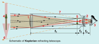
Kepschem.png
All refracting telescopes use the same principles. The combination of an objective lens 1 and some type of eyepiece 2 is used to gather more light than the human eye is able to collect on its own, focus it 5, and present the viewer with a brighter, clearer, and magnified virtual image 6

The objective in a refracting telescope refracts or bends light. This refraction causes parallel light rays to converge at a focal point; while those not parallel converge upon a focal plane. The telescope converts a bundle of parallel rays to make an angle α, with the optical axis to a second parallel bundle with angle β. The ratio β/α is called the angular magnification. It equals the ratio between the retinal image sizes obtained with and without the telescope.

Refracting telescopes can come in many different configurations to correct for image orientation and types of aberration. Because the image was formed by the bending of light, or refraction, these telescopes are called refracting telescopes or refractors.

Galileo's telescope

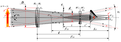
Optical diagram of Galilean telescope y – Distant object ; y′ – Real image from objective ; y″ – Magnified virtual image from eyepiece ; D – Entrance pupil diameter ; d – Virtual exit pupil diameter ; L1 – Objective lens ; L2 – Eyepiece lens e – Virtual exit pupil – Telescope equals 
 
The design Galileo Galilei used in 1609 is commonly called a Galilean telescope. It used a convergent (plano-convex) objective lens and a divergent (plano-concave) eyepiece lens (Galileo, 1610). A Galilean telescope, because the design has no intermediary focus, results in a non-inverted and upright image. 

Galileo’s best telescope magnified objects about 30 times. Because of flaws in its design, such as the shape of the lens and the narrow field of view, the images were blurry and distorted. Despite these flaws, the telescope was still good enough for Galileo to explore the sky. The Galilean telescope could view the phases of Venus, and was able to see craters on the Moon and four moons orbiting Jupiter. 

Parallel rays of light from a distant object (y) would be brought to a focus in the focal plane of the objective lens (F′ L1 / y′). The (diverging) eyepiece (L2) lens intercepts these rays and renders them parallel once more. Non-parallel rays of light from the object traveling at an angle α1 to the optical axis travel at a larger angle (α2 > α1) after they passed through the eyepiece. This leads to an increase in the apparent angular size and is responsible for the perceived magnification.

The final image (y″) is a virtual image, located at infinity and is the same way up as the object.

Keplerian telescope

Woodcut illustration of a 46 m (150 ft) focal length Keplerian astronomical refracting telescope built by Johannes Hevelius.
 
The Keplerian telescope, invented by Johannes Kepler in 1611, is an improvement on Galileo's design. It uses a convex lens as the eyepiece instead of Galileo's concave one. The advantage of this arrangement is that the rays of light emerging from the eyepiece are converging. This allows for a much wider field of view and greater eye relief, but the image for the viewer is inverted. Considerably higher magnifications can be reached with this design, but to overcome aberrations the simple objective lens needs to have a very high f-ratio (Johannes Hevelius built one with a 46-metre (150 ft) focal length, and even longer tubeless "aerial telescopes" were constructed). The design also allows for use of a micrometer at the focal plane (used to determine the angular size and/or distance between objects observed).

Achromatic refractors

The achromatic refracting lens was invented in 1733 by an English barrister named Chester Moore Hall, although it was independently invented and patented by John Dollond around 1758. The design overcame the need for very long focal lengths in refracting telescopes by using an objective made of two pieces of glass with different dispersion, 'crown' and 'flint glass', to limit the effects of chromatic and spherical aberration. Each side of each piece is ground and polished, and then the two pieces are assembled together. Achromatic lenses are corrected to bring two wavelengths (typically red and blue) into focus in the same plane. The era of the 'great refractors' in the 19th century saw large achromatic lenses culminating with the largest achromatic refractor ever built, the Great Paris Exhibition Telescope of 1900.

Apochromatic refractors

Apochromatic refractors have objectives built with special, extra-low dispersion materials. They are designed to bring three wavelengths (typically red, green, and blue) into focus in the same plane. The residual color error (tertiary spectrum) can be up to an order of magnitude less than that of an achromatic lens. Such telescopes contain elements of fluorite or special, extra-low dispersion (ED) glass in the objective and produce a very crisp image that is virtually free of chromatic aberration. Due to the special materials needed in the fabrication, apochromatic refractors are usually more expensive than telescopes of other types with a comparable aperture.

Technical considerations

The 1.0-meter (40 in) refractor, at Yerkes Observatory, the largest achromatic refractor ever put into astronomical use
 
Refractors suffer from residual chromatic and spherical aberration. This affects shorter focal ratios more than longer ones. A 100 mm (4 in) f/6 achromatic refractor is likely to show considerable color fringing (generally a purple halo around bright objects). A 100 mm (4 in) f/16 has little color fringing. 

In very large apertures, there is also a problem of lens sagging, a result of gravity deforming glass. Since a lens can only be held in place by its edge, the center of a large lens sags due to gravity, distorting the images it produces. The largest practical lens size in a refracting telescope is around 1 meter (39 in).

There is a further problem of glass defects, striae or small air bubbles trapped within the glass. In addition, glass is opaque to certain wavelengths, and even visible light is dimmed by reflection and absorption when it crosses the air-glass interfaces and passes through the glass itself. Most of these problems are avoided or diminished in reflecting telescopes, which can be made in far larger apertures and which have all but replaced refractors for astronomical research.

List of the largest refracting telescopes

A list of the largest refracting telescopes over 60 cm (24 in) diameter.

Glass (updated)

From Wikipedia, the free encyclopedia

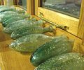
A jar made of soda-lime glass. Although transparent in thin sections, the glass is greenish-blue in thick sections from impurities. Bubbles remained trapped in the glass as it cooled from a liquid, through the glass transition, becoming a non-crystalline solid.
 
The joining of two tubes made of lead glass during glass welding.
 
Glass is a non-crystalline, amorphous solid that is often transparent and has widespread practical, technological, and decorative usage in, for example, window panes, tableware, and optoelectronics. The most familiar, and historically the oldest, types of manufactured glass are "silicate glasses" based on the chemical compound silica (silicon dioxide, or quartz), the primary constituent of sand. The term glass, in popular usage, is often used to refer only to this type of material, which is familiar from use as window glass and in glass bottles. Of the many silica-based glasses that exist, ordinary glazing and container glass is formed from a specific type called soda-lime glass, composed of approximately 75% silicon dioxide (SiO2), sodium oxide (Na2O) from sodium carbonate (Na2CO3), calcium oxide (CaO), also called lime, and several minor additives. 

Many applications of silicate glasses derive from their optical transparency, giving rise to their primary use as window panes. Glass will transmit, reflect and refract light; these qualities can be enhanced by cutting and polishing to make optical lenses, prisms, fine glassware, and optical fibers for high speed data transmission by light. Glass can be colored by adding metallic salts, and can also be painted and printed with vitreous enamels. These qualities have led to the extensive use of glass in the manufacture of art objects and in particular, stained glass windows. Although brittle, silicate glass is extremely durable, and many examples of glass fragments exist from early glass-making cultures. Because glass can be formed or molded into any shape, it has been traditionally used for vessels: bowls, vases, bottles, jars and drinking glasses. In its most solid forms it has also been used for paperweights, marbles, and beads. When extruded as glass fiber and matted as glass wool in a way to trap air, it becomes a thermal insulating material, and when these glass fibers are embedded into an organic polymer plastic, they are a key structural reinforcement part of the composite material fiberglass. Some objects historically were so commonly made of silicate glass that they are simply called by the name of the material, such as drinking glasses and eyeglasses.

Scientifically, the term "glass" is often defined in a broader sense, encompassing every solid that possesses a non-crystalline (that is, amorphous) structure at the atomic scale and that exhibits a glass transition when heated towards the liquid state. Porcelains and many polymer thermoplastics familiar from everyday use are glasses. These sorts of glasses can be made of quite different kinds of materials than silica: metallic alloys, ionic melts, aqueous solutions, molecular liquids, and polymers. For many applications, like glass bottles or eyewear, polymer glasses (acrylic glass, polycarbonate or polyethylene terephthalate) are a lighter alternative than traditional glass.

Silicate glass

Ingredients

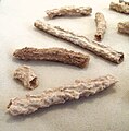
Silicon dioxide (SiO2) is a common fundamental constituent of glass. In nature, vitrification of quartz occurs when lightning strikes sand, forming hollow, branching root-like structures called fulgurites.

Fused quartz is a glass made from chemically-pure silica. It has excellent resistance to thermal shock, being able to survive immersion in water while red hot. However, its high melting temperature (1723 °C) and viscosity make it difficult to work with. Normally, other substances are added to simplify processing. One is sodium carbonate (Na2CO3, "soda"), which lowers the glass-transition temperature. The soda makes the glass water-soluble, which is usually undesirable, so lime (CaO, calcium oxide, generally obtained from limestone), some magnesium oxide (MgO) and aluminium oxide (Al2O3) are added to provide for a better chemical durability. The resulting glass contains about 70 to 74% silica by weight and is called a soda-lime glass. Soda-lime glasses account for about 90% of manufactured glass.

Most common glass contains other ingredients to change its properties. Lead glass or flint glass is more "brilliant" because the increased refractive index causes noticeably more specular reflection and increased optical dispersion. Adding barium also increases the refractive index. Thorium oxide gives glass a high refractive index and low dispersion and was formerly used in producing high-quality lenses, but due to its radioactivity has been replaced by lanthanum oxide in modern eyeglasses. Iron can be incorporated into glass to absorb infrared radiation, for example in heat-absorbing filters for movie projectors, while cerium(IV) oxide can be used for glass that absorbs ultraviolet wavelengths.

The following is a list of the more common types of silicate glasses and their ingredients, properties, and applications:
  • Fused quartz, also called fused-silica glass, vitreous-silica glass: silica (SiO2) in vitreous, or glass, form (i.e., its molecules are disordered and random, without crystalline structure). It has very low thermal expansion, is very hard, and resists high temperatures (1000–1500 °C). It is also the most resistant against weathering (caused in other glasses by alkali ions leaching out of the glass, while staining it). Fused quartz is used for high-temperature applications such as furnace tubes, lighting tubes, melting crucibles, etc.
  • Soda-lime-silica glass, window glass: silica + sodium oxide (Na2O) + lime (CaO) + magnesia (MgO) + alumina (Al2O3). Is transparent, easily formed and most suitable for window glass (see flat glass). It has a high thermal expansion and poor resistance to heat (500–600 °C). It is used for windows, some low-temperature incandescent light bulbs, and tableware. Container glass is a soda-lime glass that is a slight variation on flat glass, which uses more alumina and calcium, and less sodium and magnesium, which are more water-soluble. This makes it less susceptible to water erosion.
  • Sodium borosilicate glass, Pyrex: silica + boron trioxide (B2O3) + soda (Na2O) + alumina (Al2O3). Stands heat expansion much better than window glass. Used for chemical glassware, cooking glass, car head lamps, etc. Borosilicate glasses (e.g. Pyrex, Duran) have as main constituents silica and boron trioxide. They have fairly low coefficients of thermal expansion (7740 Pyrex CTE is 3.25×10⁶/°C as compared to about 9×10⁶/°C for a typical soda-lime glass), making them more dimensionally stable. The lower coefficient of thermal expansion (CTE) also makes them less subject to stress caused by thermal expansion, thus less vulnerable to cracking from thermal shock. They are commonly used for reagent bottles, optical components and household cookware.
  • Lead-oxide glass, crystal glass, lead glass: silica + lead oxide (PbO) + potassium oxide (K2O) + soda (Na2O) + zinc oxide (ZnO) + alumina. Because of its high density (resulting in a high electron density), it has a high refractive index, making the look of glassware more brilliant (called "crystal", though of course it is a glass and not a crystal). It also has a high elasticity, making glassware "ring". It is also more workable in the factory, but cannot stand heating very well. This kind of glass is also more fragile than other glasses and is easier to cut.
  • Aluminosilicate glass: silica + alumina + lime + magnesia + barium oxide (BaO) + boric oxide (B2O3). Extensively used for fiberglass, used for making glass-reinforced plastics (boats, fishing rods, etc.) and for halogen bulb glass. Aluminosilicate glasses are also resistant to weathering and water erosion.
  • Germanium-oxide glass: alumina + germanium dioxide (GeO2). Extremely clear glass, used for fiber-optic waveguides in communication networks. Light loses only 5% of its intensity through 1 km of glass fiber.
Another common glass ingredient is crushed alkali glass or 'cullet' ready for recycled glass. The recycled glass saves on raw materials and energy. Impurities in the cullet can lead to product and equipment failure. Fining agents such as sodium sulfate, sodium chloride, or antimony oxide may be added to reduce the number of air bubbles in the glass mixture. Glass batch calculation is the method by which the correct raw material mixture is determined to achieve the desired glass composition.

Physical properties

Optical properties

Glass is in widespread use largely due to the production of glass compositions that are transparent to visible light. In contrast, polycrystalline materials do not generally transmit visible light. The individual crystallites may be transparent, but their facets (grain boundaries) reflect or scatter light resulting in diffuse reflection. Glass does not contain the internal subdivisions associated with grain boundaries in polycrystals and hence does not scatter light in the same manner as a polycrystalline material. The surface of a glass is often smooth since during glass formation the molecules of the supercooled liquid are not forced to dispose in rigid crystal geometries and can follow surface tension, which imposes a microscopically smooth surface. These properties, which give glass its clearness, can be retained even if glass is partially light-absorbing, i.e., colored.

Glass has the ability to refract, reflect, and transmit light following geometrical optics, without scattering it (due to the absence of grain boundaries). It is used in the manufacture of lenses and windows. Common glass has a refraction index around 1.5. This may be modified by adding low-density materials such as boron, which lowers the index of refraction (see crown glass), or increased (to as much as 1.8) with high-density materials such as (classically) lead oxide (see flint glass and lead glass), or in modern uses, less toxic oxides of zirconium, titanium, or barium. These high-index glasses (inaccurately known as "crystal" when used in glass vessels) cause more chromatic dispersion of light, and are prized for their diamond-like optical properties. 

According to Fresnel equations, the reflectivity of a sheet of glass is about 4% per surface (at normal incidence in air), and the transmissivity of one element (two surfaces) is about 90%. Glass with high germanium oxide content also finds application in optoelectronics—e.g., for light-transmitting optical fibers.
Other properties

In the process of manufacture, silicate glass can be poured, formed, extruded and molded into forms ranging from flat sheets to highly intricate shapes. The finished product is brittle and will fracture, unless laminated or specially treated, but is extremely durable under most conditions. It erodes very slowly and can mostly withstand the action of water. It is mostly resistant to chemical attack, does not react with foods, and is an ideal material for the manufacture of containers for foodstuffs and most chemicals. Glass is also a fairly inert substance.

Corrosion

Although glass is generally corrosion-resistant and more corrosion resistant than other materials, it still can be corroded. The materials that make up a particular glass composition have an effect on how quickly the glass corrodes. A glass containing a high proportion of alkalis or alkali earths is less corrosion-resistant than other kinds of glasses.

Glass flakes have applications as anti-corrosive coating.

Strength

Glass typically has a tensile strength of 7 megapascals (1,000 psi), however theoretically it can have a strength of 17 gigapascals (2,500,000 psi) due to glass's strong chemical bonds. Several factors such as imperfections like scratches and bubbles and the glass's chemical composition impact the tensile strength of glass. Several processes such as toughening can increase the strength of glass.

Contemporary production

Following the glass batch preparation and mixing, the raw materials are transported to the furnace. Soda-lime glass for mass production is melted in gas fired units. Smaller scale furnaces for specialty glasses include electric melters, pot furnaces, and day tanks. After melting, homogenization and refining (removal of bubbles), the glass is formed. Flat glass for windows and similar applications is formed by the float glass process, developed between 1953 and 1957 by Sir Alastair Pilkington and Kenneth Bickerstaff of the UK's Pilkington Brothers, who created a continuous ribbon of glass using a molten tin bath on which the molten glass flows unhindered under the influence of gravity. The top surface of the glass is subjected to nitrogen under pressure to obtain a polished finish. Container glass for common bottles and jars is formed by blowing and pressing methods. This glass is often slightly modified chemically (with more alumina and calcium oxide) for greater water resistance.

Once the desired form is obtained, glass is usually annealed for the removal of stresses and to increase the glass's hardness and durability. Surface treatments, coatings or lamination may follow to improve the chemical durability (glass container coatings, glass container internal treatment), strength (toughened glass, bulletproof glass, windshields), or optical properties (insulated glazing, anti-reflective coating).

Color

Some of the many color possibilities of glass
 
Color in glass may be obtained by addition of electrically charged ions (or color centers) that are homogeneously distributed, and by precipitation of finely dispersed particles (such as in photochromic glasses). Ordinary soda-lime glass appears colorless to the naked eye when it is thin, although iron(II) oxide (FeO) impurities of up to 0.1 wt% produce a green tint, which can be viewed in thick pieces or with the aid of scientific instruments. Further FeO and chromium(III) oxide (Cr2O3) additions may be used for the production of green bottles. Sulfur, together with carbon and iron salts, is used to form iron polysulfides and produce amber glass ranging from yellowish to almost black. A glass melt can also acquire an amber color from a reducing combustion atmosphere. Manganese dioxide can be added in small amounts to remove the green tint given by iron(II) oxide. Art glass and studio glass pieces are colored using closely guarded recipes that involve specific combinations of metal oxides, melting temperatures and "cook" times. Most colored glass used in the art market is manufactured in volume by vendors who serve this market, although there are some glassmakers with the ability to make their own color from raw materials.

History of silicate glass

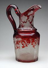
Bohemian flashed and engraved ruby glass (19th-century)
 
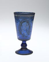
Wine goblet, mid-19th century. Qajar dynasty. Brooklyn Museum.
 
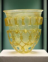
Roman cage cup from the 4th century CE
 
Studio glass. Multiple colors within a single object increase the difficulty of production, as glasses of different colors have different chemical and physical properties when molten.
 
Naturally occurring glass, especially the volcanic glass obsidian, was used by many Stone Age societies across the globe for the production of sharp cutting tools and, due to its limited source areas, was extensively traded. But in general, archaeological evidence suggests that the first true glass was made in coastal north Syria, Mesopotamia or ancient Egypt. The earliest known glass objects, of the mid third millennium BCE, were beads, perhaps initially created as accidental by-products of metal-working (slags) or during the production of faience, a pre-glass vitreous material made by a process similar to glazing.

Glass remained a luxury material, and the disasters that overtook Late Bronze Age civilizations seem to have brought glass-making to a halt. Indigenous development of glass technology in South Asia may have begun in 1730 BCE. In ancient China, though, glassmaking seems to have a late start, compared to ceramics and metal work. The term glass developed in the late Roman Empire. It was in the Roman glassmaking center at Trier, now in modern Germany, that the late-Latin term glesum originated, probably from a Germanic word for a transparent, lustrous substance. Glass objects have been recovered across the Roman Empire in domestic, funerary, and industrial contexts. Examples of Roman glass have been found outside of the former Roman Empire in China, the Baltics, the Middle East and India.

Glass was used extensively during the Middle Ages. Anglo-Saxon glass has been found across England during archaeological excavations of both settlement and cemetery sites. Glass in the Anglo-Saxon period was used in the manufacture of a range of objects including vessels, windows, beads, and was also used in jewelry. From the 10th-century onward, glass was employed in stained glass windows of churches and cathedrals, with famous examples at Chartres Cathedral and the Basilica of Saint Denis. By the 14th-century, architects were designing buildings with walls of stained glass such as Sainte-Chapelle, Paris, (1203–1248) and the East end of Gloucester Cathedral. Stained glass had a major revival with Gothic Revival architecture in the 19th century. With the Renaissance, and a change in architectural style, the use of large stained glass windows became less prevalent. The use of domestic stained glass increased until most substantial houses had glass windows. These were initially small panes leaded together, but with the changes in technology, glass could be manufactured relatively cheaply in increasingly larger sheets. This led to larger window panes, and, in the 20th-century, to much larger windows in ordinary domestic and commercial buildings. 

In the 20th century, new types of glass such as laminated glass, reinforced glass and glass bricks increased the use of glass as a building material and resulted in new applications of glass. Multi-story buildings are frequently constructed with curtain walls made almost entirely of glass. Similarly, laminated glass has been widely applied to vehicles for windscreens. Optical glass for spectacles has been used since the Middle Ages. The production of lenses has become increasingly proficient, aiding astronomers as well as having other application in medicine and science. Glass is also employed as the aperture cover in many solar energy collectors.
From the 19th century, there was a revival in many ancient glass-making techniques including cameo glass, achieved for the first time since the Roman Empire and initially mostly used for pieces in a neo-classical style. The Art Nouveau movement made great use of glass, with René Lalique, Émile Gallé, and Daum of Nancy producing colored vases and similar pieces, often in cameo glass, and also using luster techniques. Louis Comfort Tiffany in America specialized in stained glass, both secular and religious, and his famous lamps. The early 20th-century saw the large-scale factory production of glass art by firms such as Waterford and Lalique. From about 1960 onward, there have been an increasing number of small studios hand-producing glass artworks, and glass artists began to class themselves as in effect sculptors working in glass, and their works as part fine arts
In the 21st century, scientists observe the properties of ancient stained glass windows, in which suspended nanoparticles prevent UV light from causing chemical reactions that change image colors, are developing photographic techniques that use similar stained glass to capture true color images of Mars for the 2019 ESA Mars Rover mission.

Chronology of advances in architectural glass

  • 1226: "Broad Sheet" first produced in Sussex.
  • 1330: "Crown glass" for art work and vessels first produced in Rouen, France. "Broad Sheet" also produced. Both were also supplied for export.
  • 1500s: A method of making mirrors out of plate glass was developed by Venetian glassmakers on the island of Murano, who covered the back of the glass with a mercury-tin amalgam, obtaining near-perfect and undistorted reflection.
  • 1620s: "Blown plate" first produced in London. Used for mirrors and coach plates.
  • 1678: "Crown glass" first produced in London. This process dominated until the 19th century.
  • 1843: An early form of "float glass" invented by Henry Bessemer, pouring glass onto liquid tin. Expensive and not a commercial success.
  • 1874: Tempered glass is developed by Francois Barthelemy Alfred Royer de la Bastie (1830–1901) of Paris, France by quenching almost molten glass in a heated bath of oil or grease.
  • 1888: Machine-rolled glass introduced, allowing patterns.
  • 1898: Wired-cast glass first commercially produced by Pilkington for use where safety or security was an issue.
  • 1959: Float glass launched in UK. Invented by Sir Alastair Pilkington.

Other types

New chemical glass compositions or new treatment techniques can be initially investigated in small-scale laboratory experiments. The raw materials for laboratory-scale glass melts are often different from those used in mass production because the cost factor has a low priority. In the laboratory mostly pure chemicals are used. Care must be taken that the raw materials have not reacted with moisture or other chemicals in the environment (such as alkali or alkaline earth metal oxides and hydroxides, or boron oxide), or that the impurities are quantified (loss on ignition). Evaporation losses during glass melting should be considered during the selection of the raw materials, e.g., sodium selenite may be preferred over easily evaporating SeO2. Also, more readily reacting raw materials may be preferred over relatively inert ones, such as Al(OH)3 over Al2O3. Usually, the melts are carried out in platinum crucibles to reduce contamination from the crucible material. Glass homogeneity is achieved by homogenizing the raw materials mixture (glass batch), by stirring the melt, and by crushing and re-melting the first melt. The obtained glass is usually annealed to prevent breakage during processing.

To make glass from materials with poor glass forming tendencies, novel techniques are used to increase cooling rate, or reduce crystal nucleation triggers. Examples of these techniques include aerodynamic levitation (cooling the melt whilst it floats on a gas stream), splat quenching (pressing the melt between two metal anvils) and roller quenching (pouring the melt through rollers).

Fiberglass

Fiberglass (also called glass-reinforced-plastic) is a composite material made up of glass fibers (also called fiberglass or glass friller) embedded in a plastic resin. It is made by melting glass and stretching the glass into fibers. These fibers are woven together into a cloth and left to set in a plastic resin.

Fiberglass filaments are made through a pultrusion process in which the raw materials (sand, limestone, kaolin clay, fluorspar, colemanite, dolomite and other minerals) are melted in a large furnace into a liquid which is extruded through very small orifices (5–25 micrometers in diameter if the glass is E-glass and 9 micrometers if the glass is S-glass).

Fiberglass has the properties of being lightweight and corrosion resistant. Fiberglass is also a good insulator, allowing it to be used to insulate buildings. Most fiberglass is not alkali resistant. Fiberglass also has the property of becoming stronger as the glass ages.

Network glasses

A CD-RW (CD). Chalcogenide glass form the basis of rewritable CD and DVD solid-state memory technology.
 
Some types of glass that do not include silica as a major constituent may have physico-chemical properties useful for their application in fiber optics and other specialized technical applications. These include fluoride glass, aluminate and aluminosilicate glass, phosphate glass, borate glass, and chalcogenide glass

There are three classes of components for oxide glass: network formers, intermediates, and modifiers. The network formers (silicon, boron, germanium) form a highly cross-linked network of chemical bonds. The intermediates (titanium, aluminum, zirconium, beryllium, magnesium, zinc) can act as both network formers and modifiers, according to the glass composition. The modifiers (calcium, lead, lithium, sodium, potassium) alter the network structure; they are usually present as ions, compensated by nearby non-bridging oxygen atoms, bound by one covalent bond to the glass network and holding one negative charge to compensate for the positive ion nearby. Some elements can play multiple roles; e.g. lead can act both as a network former (Pb4+ replacing Si4+), or as a modifier.

The presence of non-bridging oxygen lowers the relative number of strong bonds in the material and disrupts the network, decreasing the viscosity of the melt and lowering the melting temperature.

The alkali metal ions are small and mobile; their presence in glass allows a degree of electrical conductivity, especially in molten state or at high temperature. Their mobility decreases the chemical resistance of the glass, allowing leaching by water and facilitating corrosion. Alkaline earth ions, with their two positive charges and requirement for two non-bridging oxygen ions to compensate for their charge, are much less mobile themselves and also hinder diffusion of other ions, especially the alkalis. The most common commercial glass types contain both alkali and alkaline earth ions (usually sodium and calcium), for easier processing and satisfying corrosion resistance. Corrosion resistance of glass can be increased by dealkalization, removal of the alkali ions from the glass surface by reaction with sulfur or fluorine compounds. Presence of alkaline metal ions has also detrimental effect to the loss tangent of the glass, and to its electrical resistance; glass manufactured for electronics (sealing, vacuum tubes, lamps ...) have to take this in account.

Addition of lead(II) oxide lowers melting point, lowers viscosity of the melt, and increases refractive index. Lead oxide also facilitates solubility of other metal oxides and is used in colored glass. The viscosity decrease of lead glass melt is very significant (roughly 100 times in comparison with soda glass); this allows easier removal of bubbles and working at lower temperatures, hence its frequent use as an additive in vitreous enamels and glass solders. The high ionic radius of the Pb2+ ion renders it highly immobile in the matrix and hinders the movement of other ions; lead glasses therefore have high electrical resistance, about two orders of magnitude higher than soda-lime glass (108.5 vs 106.5 Ω⋅cm, DC at 250 °C). For more details, see lead glass.

Addition of fluorine lowers the dielectric constant of glass. Fluorine is highly electronegative and attracts the electrons in the lattice, lowering the polarizability of the material. Such silicon dioxide-fluoride is used in manufacture of integrated circuits as an insulator. High levels of fluorine doping lead to formation of volatile SiF2O and such glass is then thermally unstable. Stable layers were achieved with dielectric constant down to about 3.5–3.7.

Amorphous metals

Samples of amorphous metal, with millimeter scale
 
In the past, small batches of amorphous metals with high surface area configurations (ribbons, wires, films, etc.) have been produced through the implementation of extremely rapid rates of cooling. This was initially termed "splat cooling" by doctoral student W. Klement at Caltech, who showed that cooling rates on the order of millions of degrees per second is sufficient to impede the formation of crystals, and the metallic atoms become "locked into" a glassy state. Amorphous metal wires have been produced by sputtering molten metal onto a spinning metal disk. More recently a number of alloys have been produced in layers with thickness exceeding 1 millimeter. These are known as bulk metallic glasses (BMG). Liquidmetal Technologies sell a number of zirconium-based BMGs. Batches of amorphous steel have also been produced that demonstrate mechanical properties far exceeding those found in conventional steel alloys.

In 2004, NIST researchers presented evidence that an isotropic non-crystalline metallic phase (dubbed "q-glass") could be grown from the melt. This phase is the first phase, or "primary phase", to form in the Al-Fe-Si system during rapid cooling. Experimental evidence indicates that this phase forms by a first-order transition. Transmission electron microscopy (TEM) images show that the q-glass nucleates from the melt as discrete particles, which grow spherically with a uniform growth rate in all directions. The diffraction pattern shows it to be an isotropic glassy phase. Yet there is a nucleation barrier, which implies an interfacial discontinuity (or internal surface) between the glass and the melt.

Electrolytes

Electrolytes or molten salts are mixtures of different ions. In a mixture of three or more ionic species of dissimilar size and shape, crystallization can be so difficult that the liquid can easily be supercooled into a glass. The best-studied example is Ca0.4K0.6(NO3)1.4. Glass electrolytes in the form of Ba-doped Li-glass and Ba-doped Na-glass have been proposed as solutions to problems identified with organic liquid electrolytes used in modern lithium-ion battery cells.

Aqueous solutions

Some aqueous solutions can be supercooled into a glassy state, for instance LiCl:RH2O (a solution of lithium chloride salt and water molecules) in the composition range 4 less than R less than 8. An aqueous solution containing sugar has a glassy state and can be used as a surfactant.

Molecular liquids

A molecular liquid is composed of molecules that do not form a covalent network but interact only through weak van der Waals forces or through transient hydrogen bonds. Many molecular liquids can be supercooled into a glass; some are excellent glass formers that normally do not crystallize. An example of this is sugar glass.

Under extremes of pressure and temperature solids may exhibit large structural and physical changes that can lead to polyamorphic phase transitions. In 2006 Italian scientists created an amorphous phase of carbon dioxide using extreme pressure. The substance was named amorphous carbonia (a-CO2) and exhibits an atomic structure resembling that of silica.

Polymers

Important polymer glasses include amorphous and glassy pharmaceutical compounds. These are useful because the solubility of the compound is greatly increased when it is amorphous compared to the same crystalline composition. Many emerging pharmaceuticals are practically insoluble in their crystalline forms.

Colloidal glasses

Concentrated colloidal suspensions may exhibit a distinct glass transition as function of particle concentration or density.

In cell biology, there is recent evidence suggesting that the cytoplasm behaves like a colloidal glass approaching the liquid-glass transition. During periods of low metabolic activity, as in dormancy, the cytoplasm vitrifies and prohibits the movement to larger cytoplasmic particles while allowing the diffusion of smaller ones throughout the cell.

Glass-ceramics

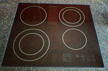
A high-strength glass-ceramic cooktop with negligible thermal expansion.
 
Glass-ceramic materials share many properties with both non-crystalline glass and crystalline ceramics. They are formed as a glass, and then partially crystallized by heat treatment. For example, the microstructure of whiteware ceramics frequently contains both amorphous and crystalline phases. Crystalline grains are often embedded within a non-crystalline intergranular phase of grain boundaries. When applied to whiteware ceramics, vitreous means the material has an extremely low permeability to liquids, often but not always water, when determined by a specified test regime.

The term mainly refers to a mix of lithium and aluminosilicates that yields an array of materials with interesting thermomechanical properties. The most commercially important of these have the distinction of being impervious to thermal shock. Thus, glass-ceramics have become extremely useful for countertop cooking. The negative thermal expansion coefficient (CTE) of the crystalline ceramic phase can be balanced with the positive CTE of the glassy phase. At a certain point (~70% crystalline) the glass-ceramic has a net CTE near zero. This type of glass-ceramic exhibits excellent mechanical properties and can sustain repeated and quick temperature changes up to 1000 °C.

Structure

As in other amorphous solids, the atomic structure of a glass lacks the long-range periodicity observed in crystalline solids. Due to chemical bonding characteristics, glasses do possess a high degree of short-range order with respect to local atomic polyhedra.

The amorphous structure of glassy silica (SiO2) in two dimensions. No long-range order is present, although there is local ordering with respect to the tetrahedral arrangement of oxygen (O) atoms around the silicon (Si) atoms.

Formation from a supercooled liquid

In physics, the standard definition of a glass (or vitreous solid) is a solid formed by rapid melt quenching, although the term glass is often used to describe any amorphous solid that exhibits a glass transition temperature Tg. For melt quenching, if the cooling is sufficiently rapid (relative to the characteristic crystallization time) then crystallization is prevented and instead the disordered atomic configuration of the supercooled liquid is frozen into the solid state at Tg. The tendency for a material to form a glass while quenched is called glass-forming ability. This ability can be predicted by the rigidity theory. Generally, a glass exists in a structurally metastable state with respect to its crystalline form, although in certain circumstances, for example in atactic polymers, there is no crystalline analogue of the amorphous phase.

Glass is sometimes considered to be a liquid due to its lack of a first-order phase transition where certain thermodynamic variables such as volume, entropy and enthalpy are discontinuous through the glass transition range. The glass transition may be described as analogous to a second-order phase transition where the intensive thermodynamic variables such as the thermal expansivity and heat capacity are discontinuous. Nonetheless, the equilibrium theory of phase transformations does not entirely hold for glass, and hence the glass transition cannot be classed as one of the classical equilibrium phase transformations in solids.

Glass is an amorphous solid. It exhibits an atomic structure close to that observed in the supercooled liquid phase but displays all the mechanical properties of a solid. The notion that glass flows to an appreciable extent over extended periods of time is not supported by empirical research or theoretical analysis. Laboratory measurements of room temperature glass flow do show a motion consistent with a material viscosity on the order of 1017–1018 Pa s.

Although the atomic structure of glass shares characteristics of the structure in a supercooled liquid, glass tends to behave as a solid below its glass transition temperature. A supercooled liquid behaves as a liquid, but it is below the freezing point of the material, and in some cases will crystallize almost instantly if a crystal is added as a core. The change in heat capacity at a glass transition and a melting transition of comparable materials are typically of the same order of magnitude, indicating that the change in active degrees of freedom is comparable as well. Both in a glass and in a crystal it is mostly only the vibrational degrees of freedom that remain active, whereas rotational and translational motion is arrested. This helps to explain why both crystalline and non-crystalline solids exhibit rigidity on most experimental time scales.

Behavior of antique glass

The observation that old windows are sometimes found to be thicker at the bottom than at the top is often offered as supporting evidence for the view that glass flows over a timescale of centuries, the assumption being that the glass has exhibited the liquid property of flowing from one shape to another. This assumption is incorrect, as once solidified, glass stops flowing. The reason for the observation is that in the past, when panes of glass were commonly made by glassblowers, the technique used was to spin molten glass so as to create a round, mostly flat and even plate (the crown glass process, described above). This plate was then cut to fit a window. The pieces were not absolutely flat; the edges of the disk became a different thickness as the glass spun. When installed in a window frame, the glass would be placed with the thicker side down both for the sake of stability and to prevent water accumulating in the lead cames at the bottom of the window. Occasionally, such glass has been found installed with the thicker side at the top, left or right.

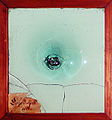
Mass production of glass window panes in the early twentieth century caused a similar effect. In glass factories, molten glass was poured onto a large cooling table and allowed to spread. The resulting glass is thicker at the location of the pour, located at the center of the large sheet. These sheets were cut into smaller window panes with nonuniform thickness, typically with the location of the pour centered in one of the panes (known as "bull's-eyes") for decorative effect. Modern glass intended for windows is produced as float glass and is very uniform in thickness. 

Several other points can be considered that contradict the "cathedral glass flow" theory:
  • Writing in the American Journal of Physics, the materials engineer Edgar D. Zanotto states "... the predicted relaxation time for GeO2 at room temperature is 1032 years. Hence, the relaxation period (characteristic flow time) of cathedral glasses would be even longer." (1032 years is many times longer than the estimated age of the universe.)
  • If medieval glass has flowed perceptibly, then ancient Roman and Egyptian objects should have flowed proportionately more—but this is not observed. Similarly, prehistoric obsidian blades should have lost their edge; this is not observed either (although obsidian may have a different viscosity from window glass).
  • If glass flows at a rate that allows changes to be seen with the naked eye after centuries, then the effect should be noticeable in antique telescopes. Any slight deformation in the antique telescopic lenses would lead to a dramatic decrease in optical performance, a phenomenon that is not observed. However, the glass used in telescopic lenses is generally different from what is used in windowpanes.

Information asymmetry

From Wikipedia, the free encyclopedia https://en.wikipedia.org/wiki/Inf...