Search This Blog

Monday, February 18, 2019

History of optics

From Wikipedia, the free encyclopedia

Optics began with the development of lenses by the ancient Egyptians and Mesopotamians, followed by theories on light and vision developed by ancient Greek philosophers, and the development of geometrical optics in the Greco-Roman world. The word optics is derived from the Greek term τα ὀπτικά meaning "appearance, look". Optics was significantly reformed by the developments in the medieval Islamic world, such as the beginnings of physical and physiological optics, and then significantly advanced in early modern Europe, where diffractive optics began. These earlier studies on optics are now known as "classical optics". The term "modern optics" refers to areas of optical research that largely developed in the 20th century, such as wave optics and quantum optics.
 
The earliest known lenses were made from polished crystal, often quartz, and have been dated as early as 750 BC for Assyrian lenses such as the Nimrud / Layard lens. There are many similar lenses from ancient Egypt, Greece and Babylon. The ancient Romans and Greeks filled glass spheres with water to make lenses. However, glass lenses were not thought of until the Middle Ages.

Some lenses fixed in ancient Egyptian statues are much older than those mentioned above. There is some doubt as to whether or not they qualify as lenses, but they are undoubtedly glass and served at least ornamental purposes. The statues appear to be anatomically correct schematic eyes.

In ancient India, the philosophical schools of Samkhya and Vaisheshika, from around the 6th–5th century BC, developed theories on light. According to the Samkhya school, light is one of the five fundamental "subtle" elements (tanmatra) out of which emerge the gross elements.

In contrast, the Vaisheshika school gives an atomic theory of the physical world on the non-atomic ground of ether, space and time. The basic atoms are those of earth (prthivı), water (apas), fire (tejas), and air (vayu), that should not be confused with the ordinary meaning of these terms. These atoms are taken to form binary molecules that combine further to form larger molecules. Motion is defined in terms of the movement of the physical atoms. Light rays are taken to be a stream of high velocity of tejas (fire) atoms. The particles of light can exhibit different characteristics depending on the speed and the arrangements of the tejas atoms. Around the first century BC, the Vishnu Purana refers to sunlight as "the seven rays of the sun". 

In the fifth century BC, Empedocles postulated that everything was composed of four elements; fire, air, earth and water. He believed that Aphrodite made the human eye out of the four elements and that she lit the fire in the eye which shone out from the eye making sight possible. If this were true, then one could see during the night just as well as during the day, so Empedocles postulated an interaction between rays from the eyes and rays from a source such as the sun. He stated that light has a finite speed.

In his Optics Greek mathematician Euclid observed that "things seen under a greater angle appear greater, and those under a lesser angle less, while those under equal angles appear equal". In the 36 propositions that follow, Euclid relates the apparent size of an object to its distance from the eye and investigates the apparent shapes of cylinders and cones when viewed from different angles. Pappus believed these results to be important in astronomy and included Euclid's Optics, along with his Phaenomena, in the Little Astronomy, a compendium of smaller works to be studied before the Syntaxis (Almagest) of Ptolemy

In 55 BC, Lucretius, a Roman who carried on the ideas of earlier Greek atomists, wrote:
The light and heat of the sun; these are composed of minute atoms which, when they are shoved off, lose no time in shooting right across the interspace of air in the direction imparted by the shove.
— Lucretius, On the nature of the Universe
Despite being similar to later particle theories of light, Lucretius's views were not generally accepted and light was still theorized as emanating from the eye. 

In his Catoptrica, Hero of Alexandria showed by a geometrical method that the actual path taken by a ray of light reflected from a plane mirror is shorter than any other reflected path that might be drawn between the source and point of observation. 

In the second century Claudius Ptolemy, in his Optics undertook studies of reflection and refraction. He measured the angles of refraction between air, water, and glass, and his published results indicate that he adjusted his measurements to fit his (incorrect) assumption that the angle of refraction is proportional to the angle of incidence.

The Indian Buddhists, such as Dignāga in the 5th century and Dharmakirti in the 7th century, developed a type of atomism that is a philosophy about reality being composed of atomic entities that are momentary flashes of light or energy. They viewed light as being an atomic entity equivalent to energy, similar to the modern concept of photons, though they also viewed all matter as being composed of these light/energy particles.

Geometrical optics

The early writers discussed here treated vision more as a geometrical than as a physical, physiological, or psychological problem. The first known author of a treatise on geometrical optics was the geometer Euclid (c. 325 BC–265 BC). Euclid began his study of optics as he began his study of geometry, with a set of self-evident axioms.
  1. Lines (or visual rays) can be drawn in a straight line to the object.
  2. Those lines falling upon an object form a cone.
  3. Those things upon which the lines fall are seen.
  4. Those things seen under a larger angle appear larger.
  5. Those things seen by a higher ray, appear higher.
  6. Right and left rays appear right and left.
  7. Things seen within several angles appear clearer.
Euclid did not define the physical nature of these visual rays but, using the principles of geometry, he discussed the effects of perspective and the rounding of things seen at a distance.

Where Euclid had limited his analysis to simple direct vision, Hero of Alexandria (c. AD 10–70) extended the principles of geometrical optics to consider problems of reflection (catoptrics). Unlike Euclid, Hero occasionally commented on the physical nature of visual rays, indicating that they proceeded at great speed from the eye to the object seen and were reflected from smooth surfaces but could become trapped in the porosities of unpolished surfaces. This has come to be known as emission theory.

Hero demonstrated the equality of the angle of incidence and reflection on the grounds that this is the shortest path from the object to the observer. On this basis, he was able to define the fixed relation between an object and its image in a plane mirror. Specifically, the image appears to be as far behind the mirror as the object really is in front of the mirror.

Like Hero, Ptolemy in his Optics (preserved only in the form of a Latin translation of a gravely defective Arabic version) considered the visual rays as proceeding from the eye to the object seen, but, unlike Hero, considered that the visual rays were not discrete lines, but formed a continuous cone. Ptolemy extended the study of vision beyond direct and reflected vision; he also studied vision by refracted rays (dioptrics), when we see objects through the interface between two media of different density. He conducted experiments to measure the path of vision when we look from air to water, from air to glass, and from water to glass and tabulated the relationship between the incident and refracted rays.

His tabulated results have been studied for the air water interface, and in general the values he obtained reflect the theoretical refraction given by modern theory, but the outliers are distorted to represent Ptolemy's a priori model of the nature of refraction.

In the Islamic world

Reproduction of a page of Ibn Sahl's manuscript showing his discovery of the law of refraction, now known as Snell's law.
 
Al-Kindi (c. 801–873) was one of the earliest important optical writers in the Islamic world. In a work known in the west as De radiis stellarum, al-Kindi developed a theory "that everything in the world ... emits rays in every direction, which fill the whole world."


This theory of the active power of rays had an influence on later scholars such as Ibn al-Haytham, Robert Grosseteste and Roger Bacon.

Ibn Sahl, a mathematician active in Baghdad during the 980s, is the first Islamic scholar known to have compiled a commentary on Ptolemy's Optics. His treatise Fī al-'āla al-muḥriqa "On the burning instruments" was reconstructed from fragmentary manuscripts by Rashed (1993). The work is concerned with how curved mirrors and lenses bend and focus light. Ibn Sahl also describes a law of refraction mathematically equivalent to Snell's law. He used his law of refraction to compute the shapes of lenses and mirrors that focus light at a single point on the axis.

Ibn al-Haytham (known in as Alhacen or Alhazen in Western Europe), writing in the 1010s, received both Ibn Sahl's treatise and a partial Arabic translation of Ptolemy's Optics. He produced a comprehensive and systematic analysis of Greek optical theories. Ibn al-Haytham's key achievement was twofold: first, to insist, against the opinion of Ptolemy, that vision occurred because of rays entering the eye; the second was to define the physical nature of the rays discussed by earlier geometrical optical writers, considering them as the forms of light and color. He then analyzed these physical rays according to the principles of geometrical optics. He wrote many books on optics, most significantly the Book of Optics (Kitab al Manazir in Arabic), translated into Latin as the De aspectibus or Perspectiva, which disseminated his ideas to Western Europe and had great influence on the later developments of optics.

Avicenna (980-1037) agreed with Alhazen that the speed of light is finite, as he "observed that if the perception of light is due to the emission of some sort of particles by a luminous source, the speed of light must be finite." Abū Rayhān al-Bīrūnī (973-1048) also agreed that light has a finite speed, and stated that the speed of light is much faster than the speed of sound.

Abu 'Abd Allah Muhammad ibn Ma'udh, who lived in Al-Andalus during the second half of the 11th century, wrote a work on optics later translated into Latin as Liber de crepisculis, which was mistakenly attributed to Alhazen. This was a "short work containing an estimation of the angle of depression of the sun at the beginning of the morning twilight and at the end of the evening twilight, and an attempt to calculate on the basis of this and other data the height of the atmospheric moisture responsible for the refraction of the sun's rays." Through his experiments, he obtained the value of 18°, which comes close to the modern value.

In the late 13th and early 14th centuries, Qutb al-Din al-Shirazi (1236–1311) and his student Kamāl al-Dīn al-Fārisī (1260–1320) continued the work of Ibn al-Haytham, and they were among the first to give the correct explanations for the rainbow phenomenon. Al-Fārisī published his findings in his Kitab Tanqih al-Manazir (The Revision of [Ibn al-Haytham's] Optics).

In medieval Europe

The English bishop, Robert Grosseteste (c. 1175–1253), wrote on a wide range of scientific topics at the time of the origin of the medieval university and the recovery of the works of Aristotle. Grosseteste reflected a period of transition between the Platonism of early medieval learning and the new Aristotelianism, hence he tended to apply mathematics and the Platonic metaphor of light in many of his writings. He has been credited with discussing light from four different perspectives: an epistemology of light, a metaphysics or cosmogony of light, an etiology or physics of light, and a theology of light.

Setting aside the issues of epistemology and theology, Grosseteste's cosmogony of light describes the origin of the universe in what may loosely be described as a medieval "big bang" theory. Both his biblical commentary, the Hexaemeron (1230 x 35), and his scientific On Light (1235 x 40), took their inspiration from Genesis 1:3, "God said, let there be light", and described the subsequent process of creation as a natural physical process arising from the generative power of an expanding (and contracting) sphere of light.

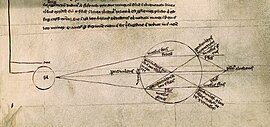
Optical diagram showing light being refracted by a spherical glass container full of water. (from Roger Bacon, De multiplicatione specierum)
 
His more general consideration of light as a primary agent of physical causation appears in his On Lines, Angles, and Figures where he asserts that "a natural agent propagates its power from itself to the recipient" and in On the Nature of Places where he notes that "every natural action is varied in strength and weakness through variation of lines, angles and figures."

The English Franciscan, Roger Bacon (c. 1214–1294) was strongly influenced by Grosseteste's writings on the importance of light. In his optical writings (the Perspectiva, the De multiplicatione specierum, and the De speculis comburentibus) he cited a wide range of recently translated optical and philosophical works, including those of Alhacen, Aristotle, Avicenna, Averroes, Euclid, al-Kindi, Ptolemy, Tideus, and Constantine the African. Although he was not a slavish imitator, he drew his mathematical analysis of light and vision from the writings of the Arabic writer, Alhacen. But he added to this the Neoplatonic concept, perhaps drawn from Grosseteste, that every object radiates a power (species) by which it acts upon nearby objects suited to receive those species. Note that Bacon's optical use of the term "species" differs significantly from the genus / species categories found in Aristotelian philosophy.

Several later works, including the influential A Moral Treatise on the Eye (Latin: Tractatus Moralis de Oculo) by Peter of Limoges (1240–1306), helped popularize and spread the ideas found in Bacon's writings.

Another English Franciscan, John Pecham (died 1292) built on the work of Bacon, Grosseteste, and a diverse range of earlier writers to produce what became the most widely used textbook on Optics of the Middle Ages, the Perspectiva communis. His book centered on the question of vision, on how we see, rather than on the nature of light and color. Pecham followed the model set forth by Alhacen, but interpreted Alhacen's ideas in the manner of Roger Bacon.

Like his predecessors, Witelo (c. 1230–1280 x 1314) drew on the extensive body of optical works recently translated from Greek and Arabic to produce a massive presentation of the subject entitled the Perspectiva. His theory of vision follows Alhacen and he does not consider Bacon's concept of species, although passages in his work demonstrate that he was influenced by Bacon's ideas. Judging from the number of surviving manuscripts, his work was not as influential as those of Pecham and Bacon, yet his importance, and that of Pecham, grew with the invention of printing.

Theodoric of Freiberg (ca. 1250–ca. 1310) was among the first in Europe to provide the correct scientific explanation for the rainbow phenomenon, as well as Qutb al-Din al-Shirazi (1236–1311) and his student Kamāl al-Dīn al-Fārisī (1260–1320) mentioned above.

Renaissance and Early Modern

Johannes Kepler (1571–1630) picked up the investigation of the laws of optics from his lunar essay of 1600. Both lunar and solar eclipses presented unexplained phenomena, such as unexpected shadow sizes, the red color of a total lunar eclipse, and the reportedly unusual light surrounding a total solar eclipse. Related issues of atmospheric refraction applied to all astronomical observations. Through most of 1603, Kepler paused his other work to focus on optical theory; the resulting manuscript, presented to the emperor on January 1, 1604, was published as Astronomiae Pars Optica (The Optical Part of Astronomy). In it, Kepler described the inverse-square law governing the intensity of light, reflection by flat and curved mirrors, and principles of pinhole cameras, as well as the astronomical implications of optics such as parallax and the apparent sizes of heavenly bodies. Astronomiae Pars Optica is generally recognized as the foundation of modern optics (though the law of refraction is conspicuously absent).

Willebrord Snellius (1580–1626) found the mathematical law of refraction, now known as Snell's law, in 1621. Subsequently, René Descartes (1596–1650) showed, by using geometric construction and the law of refraction (also known as Descartes' law), that the angular radius of a rainbow is 42° (i.e. the angle subtended at the eye by the edge of the rainbow and the rainbow's center is 42°). He also independently discovered the law of reflection, and his essay on optics was the first published mention of this law.

Christiaan Huygens (1629–1695) wrote several works in the area of optics. These included the Opera reliqua (also known as Christiani Hugenii Zuilichemii, dum viveret Zelhemii toparchae, opuscula posthuma) and the Traité de la lumière

Isaac Newton (1643–1727) investigated the refraction of light, demonstrating that a prism could decompose white light into a spectrum of colors, and that a lens and a second prism could recompose the multicolored spectrum into white light. He also showed that the colored light does not change its properties by separating out a colored beam and shining it on various objects. Newton noted that regardless of whether it was reflected or scattered or transmitted, it stayed the same colour. Thus, he observed that color is the result of objects interacting with already-colored light rather than objects generating the color themselves. This is known as Newton's theory of color. From this work he concluded that any refracting telescope would suffer from the dispersion of light into colors, and invented a reflecting telescope (today known as a Newtonian telescope) to bypass that problem. By grinding his own mirrors, using Newton's rings to judge the quality of the optics for his telescopes, he was able to produce a superior instrument to the refracting telescope, due primarily to the wider diameter of the mirror. In 1671 the Royal Society asked for a demonstration of his reflecting telescope. Their interest encouraged him to publish his notes On Colour, which he later expanded into his Opticks. Newton argued that light is composed of particles or corpuscles and were refracted by accelerating toward the denser medium, but he had to associate them with waves to explain the diffraction of light (Opticks Bk. II, Props. XII-L). Later physicists instead favored a purely wavelike explanation of light to account for diffraction. Today's quantum mechanics, photons and the idea of wave-particle duality bear only a minor resemblance to Newton's understanding of light. 

In his Hypothesis of Light of 1675, Newton posited the existence of the ether to transmit forces between particles. In 1704, Newton published Opticks, in which he expounded his corpuscular theory of light. He considered light to be made up of extremely subtle corpuscles, that ordinary matter was made of grosser corpuscles and speculated that through a kind of alchemical transmutation "Are not gross Bodies and Light convertible into one another, ...and may not Bodies receive much of their Activity from the Particles of Light which enter their Composition?"

Diffractive optics

Thomas Young's sketch of two-slit diffraction, which he presented to the Royal Society in 1803
 
The effects of diffraction of light were carefully observed and characterized by Francesco Maria Grimaldi, who also coined the term diffraction, from the Latin diffringere, 'to break into pieces', referring to light breaking up into different directions. The results of Grimaldi's observations were published posthumously in 1665. Isaac Newton studied these effects and attributed them to inflexion of light rays. James Gregory (1638–1675) observed the diffraction patterns caused by a bird feather, which was effectively the first diffraction grating. In 1803 Thomas Young did his famous experiment observing interference from two closely spaced slits in his double slit interferometer. Explaining his results by interference of the waves emanating from the two different slits, he deduced that light must propagate as waves. Augustin-Jean Fresnel did more definitive studies and calculations of diffraction, published in 1815 and 1818, and thereby gave great support to the wave theory of light that had been advanced by Christiaan Huygens and reinvigorated by Young, against Newton's particle theory.

Lenses and lensmaking

The earliest known lenses were made from polished crystal, often quartz, and have been dated as early as 750 BC for Assyrian lenses such as the Layard / Nimrud lens. There are many similar lenses from ancient Egypt, Greece and Babylon. The ancient Romans and Greeks filled glass spheres with water to make lenses. 

The earliest historical reference to magnification dates back to ancient Egyptian hieroglyphs in the 5th century BC, which depict "simple glass meniscal lenses". The earliest written record of magnification dates back to the 1st century AD, when Seneca the Younger, a tutor of Emperor Nero, wrote: "Letters, however small and indistinct, are seen enlarged and more clearly through a globe or glass filled with water". Emperor Nero is also said to have watched the gladiatorial games using an emerald as a corrective lens.

Ibn al-Haytham (Alhacen) wrote about the effects of pinhole, concave lenses, and magnifying glasses in his Book of Optics. Roger Bacon used parts of glass spheres as magnifying glasses and recommended them to be used to help people read. Roger Bacon got his inspiration from Alhacen in the 11th century. He discovered that light reflects from objects rather than emanating from them.

Between the 11th and 13th century "reading stones" were invented. Often used by monks to assist in illuminating manuscripts, these were primitive plano-convex lenses initially made by cutting a glass sphere in half. As the stones were experimented with, it was slowly understood that shallower lenses magnified more effectively. Around 1286, possibly in Pisa, Italy, the first pair of eyeglasses were made, although it is unclear who the inventor was.

The earliest known working telescopes were the refracting telescopes that appeared in the Netherlands in 1608. Their inventor is unknown: Hans Lippershey applied for the first patent that year followed by a patent application by Jacob Metius of Alkmaar two weeks later (neither was granted since examples of the device seemed to be numerous at the time). Galileo greatly improved upon these designs the following year. Isaac Newton is credited with constructing the first functional reflecting telescope in 1668, his Newtonian reflector

The earliest known examples of compound microscopes, which combine an objective lens near the specimen with an eyepiece to view a real image, appeared in Europe around 1620. The design is very similar to the telescope and, like that device, its inventor is unknown. Again claims revolve around the spectacle making centers in the Netherlands including claims it was invented in 1590 by Zacharias Janssen and/or his father, Hans Martens, claims it was invented by rival spectacle maker, Hans Lippershey, and claims it was invented by expatriate Cornelis Drebbel who was noted to have a version in London in 1619. Galileo Galilei (also sometimes cited as a compound microscope inventor) seems to have found after 1609 that he could close focus his telescope to view small objects and, after seeing a compound microscope built by Drebbel exhibited in Rome in 1624, built his own improved version. The name "microscope" was coined by Giovanni Faber, who gave that name to Galileo Galilei's compound microscope in 1625.

Quantum optics

Light is made up of particles called photons and hence inherently is quantized. Quantum optics is the study of the nature and effects of light as quantized photons. The first indication that light might be quantized came from Max Planck in 1899 when he correctly modeled blackbody radiation by assuming that the exchange of energy between light and matter only occurred in discrete amounts he called quanta. It was unknown whether the source of this discreteness was the matter or the light. In 1905, Albert Einstein published the theory of the photoelectric effect. It appeared that the only possible explanation for the effect was the quantization of light itself. Later, Niels Bohr showed that atoms could only emit discrete amounts of energy. The understanding of the interaction between light and matter following from these developments not only formed the basis of quantum optics but also were crucial for the development of quantum mechanics as a whole. However, the subfields of quantum mechanics dealing with matter-light interaction were principally regarded as research into matter rather than into light and hence, one rather spoke of atom physics and quantum electronics.

This changed with the invention of the maser in 1953 and the laser in 1960. Laser science—research into principles, design and application of these devices—became an important field, and the quantum mechanics underlying the laser's principles was studied now with more emphasis on the properties of light, and the name quantum optics became customary.

As laser science needed good theoretical foundations, and also because research into these soon proved very fruitful, interest in quantum optics rose. Following the work of Dirac in quantum field theory, George Sudarshan, Roy J. Glauber, and Leonard Mandel applied quantum theory to the electromagnetic field in the 1950s and 1960s to gain a more detailed understanding of photodetection and the statistics of ligh. This led to the introduction of the coherent state as a quantum description of laser light and the realization that some states of light could not be described with classical waves. In 1977, Kimble et al. demonstrated the first source of light which required a quantum description: a single atom that emitted one photon at a time. Another quantum state of light with certain advantages over any classical state, squeezed light, was soon proposed. At the same time, development of short and ultrashort laser pulses—created by Q-switching and mode-locking techniques—opened the way to the study of unimaginably fast ("ultrafast") processes. Applications for solid state research (e.g. Raman spectroscopy) were found, and mechanical forces of light on matter were studied. The latter led to levitating and positioning clouds of atoms or even small biological samples in an optical trap or optical tweezers by laser beam. This, along with Doppler cooling was the crucial technology needed to achieve the celebrated Bose–Einstein condensation

Other remarkable results are the demonstration of quantum entanglement, quantum teleportation, and (recently, in 1995) quantum logic gates. The latter are of much interest in quantum information theory, a subject which partly emerged from quantum optics, partly from theoretical computer science.

Today's fields of interest among quantum optics researchers include parametric down-conversion, parametric oscillation, even shorter (attosecond) light pulses, use of quantum optics for quantum information, manipulation of single atoms, Bose–Einstein condensates, their application, and how to manipulate them (a sub-field often called atom optics), and much more.

Optical microscope

From Wikipedia, the free encyclopedia

Microscope
UsesSmall sample observation
Notable experimentsDiscovery of cells
Related itemsMicroscope
Electron microscope
Scanning probe microscope
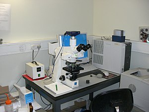
A modern microscope with a mercury bulb for fluorescence microscopy. The microscope has a digital camera, and is attached to a computer.
 
The optical microscope, often referred to as the light microscope, is a type of microscope that commonly uses visible light and a system of lenses to magnify images of small objects. Optical microscopes are the oldest design of microscope and were possibly invented in their present compound form in the 17th century. Basic optical microscopes can be very simple, although many complex designs aim to improve resolution and sample contrast. Often used in the classroom and at home unlike the electron microscope which is used for closer viewing. 

The image from an optical microscope can be captured by normal, photosensitive cameras to generate a micrograph. Originally images were captured by photographic film, but modern developments in CMOS and charge-coupled device (CCD) cameras allow the capture of digital images. Purely digital microscopes are now available which use a CCD camera to examine a sample, showing the resulting image directly on a computer screen without the need for eyepieces.

Alternatives to optical microscopy which do not use visible light include scanning electron microscopy and transmission electron microscopy and scanning probe microscopy.

On 8 October 2014, the Nobel Prize in Chemistry was awarded to Eric Betzig, William Moerner and Stefan Hell for "the development of super-resolved fluorescence microscopy," which brings "optical microscopy into the nanodimension".

Types

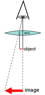
Diagram of a simple microscope
 
There are two basic types of optical microscopes: simple microscopes and compound microscopes. A simple microscope is one which uses a single lens for magnification, such as a magnifying glass. A compound microscope uses several lenses to enhance the magnification of an object. The vast majority of modern research microscopes are compound microscopes while some cheaper commercial digital microscopes are simple single lens microscopes. Compound microscopes can be further divided into a variety of other types of microscopes which differ in their optical configurations, cost, and intended purposes.

Regular microscope

A regular microscope uses a lens or set of lenses to enlarge an object through angular magnification alone, giving the viewer an erect enlarged virtual image. The use of a single convex lens or groups of lenses are found in simple magnification devices such as the magnifying glass, loupes, and eyepieces for telescopes and microscopes.

Compound microscope

Diagram of a compound microscope
 
A compound microscope uses a lens close to the object being viewed to collect light (called the objective lens) which focuses a real image of the object inside the microscope (image 1). That image is then magnified by a second lens or group of lenses (called the eyepiece) that gives the viewer an enlarged inverted virtual image of the object (image 2). The use of a compound objective/eyepiece combination allows for much higher magnification. Common compound microscopes often feature exchangeable objective lenses, allowing the user to quickly adjust the magnification. A compound microscope also enables more advanced illumination setups, such as phase contrast.

Other microscope variants

There are many variants of the compound optical microscope design for specialized purposes. Some of these are physical design differences allowing specialization for certain purposes:
  • Stereo microscope, a low-powered microscope which provides a stereoscopic view of the sample, commonly used for dissection.
  • Comparison microscope, which has two separate light paths allowing direct comparison of two samples via one image in each eye.
  • Inverted microscope, for studying samples from below; useful for cell cultures in liquid, or for metallography.
  • Fiber optic connector inspection microscope, designed for connector end-face inspection
  • Traveling microscope, for studying samples of high optical resolution.
Other microscope variants are designed for different illumination techniques:
  • Petrographic microscope, whose design usually includes a polarizing filter, rotating stage and gypsum plate to facilitate the study of minerals or other crystalline materials whose optical properties can vary with orientation.
  • Polarizing microscope, similar to the petrographic microscope.
  • Phase contrast microscope, which applies the phase contrast illumination method.
  • Epifluorescence microscope, designed for analysis of samples which include fluorophores.
  • Confocal microscope, a widely used variant of epifluorescent illumination which uses a scanning laser to illuminate a sample for fluorescence.
  • Two-photon microscope, used to image fluorescence deeper in scattering media and reduce photobleaching, especially in living samples.
  • Student microscope – an often low-power microscope with simplified controls and sometimes low quality optics designed for school use or as a starter instrument for children.
  • Ultramicroscope, an adapted light microscope that uses light scattering to allow viewing of tiny particles whose diameter is below or near the wavelength of visible light (around 500 nanometers); mostly obsolete since the advent of electron microscopes

Digital microscope

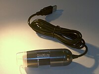
A miniature USB microscope.

A digital microscope is a microscope equipped with a digital camera allowing observation of a sample via a computer. Microscopes can also be partly or wholly computer-controlled with various levels of automation. Digital microscopy allows greater analysis of a microscope image, for example measurements of distances and areas and quantitaton of a fluorescent or histological stain.

Low-powered digital microscopes, USB microscopes, are also commercially available. These are essentially webcams with a high-powered macro lens and generally do not use transillumination. The camera attached directly to the USB port of a computer, so that the images are shown directly on the monitor. They offer modest magnifications (up to about 200×) without the need to use eyepieces, and at very low cost. High power illumination is usually provided by an LED source or sources adjacent to the camera lens. 

Digital microscopy with very low light levels to avoid damage to vulnerable biological samples is available using sensitive photon-counting digital cameras. It has been demonstrated that a light source providing pairs of entangled photons may minimize the risk of damage to the most light-sensitive samples. In this application of ghost imaging to photon-sparse microscopy, the sample is illuminated with infrared photons, each of which is spatially correlated with an entangled partner in the visible band for efficient imaging by a photon-counting camera.

History

Invention

The earliest microscopes were single lens magnifying glasses with limited magnification which date at least as far back as the widespread use of lenses in eyeglasses in the 13th century.

Compound microscopes first appeared in Europe around 1620 including one demonstrated by Cornelis Drebbel in London (around 1621) and one exhibited in Rome in 1624.

The actual inventor of the compound microscope is unknown although many claims have been made over the years. These include a claim 35 years after they appeared by Dutch spectacle-maker Johannes Zachariassen that his father, Zacharias Janssen, invented the compound microscope and/or the telescope as early as 1590. Johannes' (some claim dubious) testimony pushes the invention date so far back that Zacharias would have been a child at the time, leading to speculation that, for Johannes' claim to be true, the compound microscope would have to have been invented by Johannes' grandfather, Hans Martens. Another claim is that Janssen's competitor, Hans Lippershey (who applied for the first telescope patent in 1608) also invented the compound microscope. Other historians point to the Dutch innovator Cornelis Drebbel with his 1621 compound microscope.

Galileo Galilei is also sometimes cited as a compound microscope inventor. After 1610 he found that he could close focus his telescope to view small objects, such as flies, close up and/or could look through the wrong end in reverse to magnify small objects. The only drawback was that his 2 foot long telescope had to be extended out to 6 feet to view objects that close. After seeing the compound microscope built by Drebbel exhibited in Rome in 1624, Galileo built his own improved version. In 1625 Giovanni Faber coined the name microscope for the compound microscope Galileo submitted to the Accademia dei Lincei in 1624 (Galileo had called it the "occhiolino" or "little eye"). Faber coined the name from the Greek words μικρόν (micron) meaning "small", and σκοπεῖν (skopein) meaning "to look at", a name meant to be analogous with "telescope", another word coined by the Linceans.

Christiaan Huygens, another Dutchman, developed a simple 2-lens ocular system in the late 17th century that was achromatically corrected, and therefore a huge step forward in microscope development. The Huygens ocular is still being produced to this day, but suffers from a small field size, and other minor disadvantages.

Popularization

The oldest published image known to have been made with a microscope: bees by Francesco Stelluti, 1630
 
Antonie van Leeuwenhoek (1632–1724) is credited with bringing the microscope to the attention of biologists, even though simple magnifying lenses were already being produced in the 16th century. Van Leeuwenhoek's home-made microscopes were simple microscopes, with a single very small, yet strong lens. They were awkward in use, but enabled van Leeuwenhoek to see detailed images. It took about 150 years of optical development before the compound microscope was able to provide the same quality image as van Leeuwenhoek's simple microscopes, due to difficulties in configuring multiple lenses. In the 1850s John Leonard Riddell, Professor of Chemistry at Tulane University, invented the first practical binocular microscope while carrying out one of the earliest and most extensive American microscopic investigations of cholera.

Lighting techniques

While basic microscope technology and optics have been available for over 400 years it is much more recently that techniques in sample illumination were developed to generate the high quality images seen today. 

In August 1893 August Köhler developed Köhler illumination. This method of sample illumination gives rise to extremely even lighting and overcomes many limitations of older techniques of sample illumination. Before development of Köhler illumination the image of the light source, for example a lightbulb filament, was always visible in the image of the sample.

The Nobel Prize in physics was awarded to Dutch physicist Frits Zernike in 1953 for his development of phase contrast illumination which allows imaging of transparent samples. By using interference rather than absorption of light, extremely transparent samples, such as live mammalian cells, can be imaged without having to use staining techniques. Just two years later, in 1955, Georges Nomarski published the theory for differential interference contrast microscopy, another interference-based imaging technique.

Fluorescence microscopy

Modern biological microscopy depends heavily on the development of fluorescent probes for specific structures within a cell. In contrast to normal trans-illuminated light microscopy, in fluorescence microscopy the sample is illuminated through the objective lens with a narrow set of wavelengths of light. This light interacts with fluorophores in the sample which then emit light of a longer wavelength. It is this emitted light which makes up the image.

Since the mid 20th century chemical fluorescent stains, such as DAPI which binds to DNA, have been used to label specific structures within the cell. More recent developments include immunofluorescence, which uses fluorescently labelled antibodies to recognize specific proteins within a sample, and fluorescent proteins like GFP which a live cell can express making it fluorescent.

Components

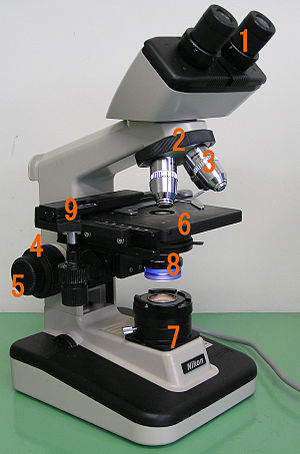
Basic optical transmission microscope elements (1990s)
 
All modern optical microscopes designed for viewing samples by transmitted light share the same basic components of the light path. In addition, the vast majority of microscopes have the same 'structural' components (numbered below according to the image on the right):
  • Eyepiece (ocular lens) (1)
  • Objective turret, revolver, or revolving nose piece (to hold multiple objective lenses) (2)
  • Objective lenses (3)
  • Focus knobs (to move the stage)
    • Coarse adjustment (4)
    • Fine adjustment (5)
  • Stage (to hold the specimen) (6)
  • Light source (a light or a mirror) (7)
  • Diaphragm and condenser (8)
  • Mechanical stage (9)

Eyepiece (ocular lens)

The eyepiece, or ocular lens, is a cylinder containing two or more lenses; its function is to bring the image into focus for the eye. The eyepiece is inserted into the top end of the body tube. Eyepieces are interchangeable and many different eyepieces can be inserted with different degrees of magnification. Typical magnification values for eyepieces include 5×, 10× (the most common), 15× and 20×. In some high performance microscopes, the optical configuration of the objective lens and eyepiece are matched to give the best possible optical performance. This occurs most commonly with apochromatic objectives.

Objective turret (revolver or revolving nose piece)

Objective turret, revolver, or revolving nose piece is the part that holds the set of objective lenses. It allows the user to switch between objective lenses.

Objective

At the lower end of a typical compound optical microscope, there are one or more objective lenses that collect light from the sample. The objective is usually in a cylinder housing containing a glass single or multi-element compound lens. Typically there will be around three objective lenses screwed into a circular nose piece which may be rotated to select the required objective lens. These arrangements are designed to be parfocal, which means that when one changes from one lens to another on a microscope, the sample stays in focus. Microscope objectives are characterized by two parameters, namely, magnification and numerical aperture. The former typically ranges from 5× to 100× while the latter ranges from 0.14 to 0.7, corresponding to focal lengths of about 40 to 2 mm, respectively. Objective lenses with higher magnifications normally have a higher numerical aperture and a shorter depth of field in the resulting image. Some high performance objective lenses may require matched eyepieces to deliver the best optical performance.

Oil immersion objective

Two Leica oil immersion microscope objective lenses: 100× (left) and 40× (right)

Some microscopes make use of oil-immersion objectives or water-immersion objectives for greater resolution at high magnification. These are used with index-matching material such as immersion oil or water and a matched cover slip between the objective lens and the sample. The refractive index of the index-matching material is higher than air allowing the objective lens to have a larger numerical aperture (greater than 1) so that the light is transmitted from the specimen to the outer face of the objective lens with minimal refraction. Numerical apertures as high as 1.6 can be achieved. The larger numerical aperture allows collection of more light making detailed observation of smaller details possible. An oil immersion lens usually has a magnification of 40 to 100×.

Focus knobs

Adjustment knobs move the stage up and down with separate adjustment for coarse and fine focusing. The same controls enable the microscope to adjust to specimens of different thickness. In older designs of microscopes, the focus adjustment wheels move the microscope tube up or down relative to the stand and had a fixed stage.

Frame

The whole of the optical assembly is traditionally attached to a rigid arm, which in turn is attached to a robust U-shaped foot to provide the necessary rigidity. The arm angle may be adjustable to allow the viewing angle to be adjusted. 

The frame provides a mounting point for various microscope controls. Normally this will include controls for focusing, typically a large knurled wheel to adjust coarse focus, together with a smaller knurled wheel to control fine focus. Other features may be lamp controls and/or controls for adjusting the condenser.

Stage

The stage is a platform below the objective which supports the specimen being viewed. In the center of the stage is a hole through which light passes to illuminate the specimen. The stage usually has arms to hold slides (rectangular glass plates with typical dimensions of 25×75 mm, on which the specimen is mounted). 

At magnifications higher than 100× moving a slide by hand is not practical. A mechanical stage, typical of medium and higher priced microscopes, allows tiny movements of the slide via control knobs that reposition the sample/slide as desired. If a microscope did not originally have a mechanical stage it may be possible to add one. 

All stages move up and down for focus. With a mechanical stage slides move on two horizontal axes for positioning the specimen to examine specimen details.

Focusing starts at lower magnification in order to center the specimen by the user on the stage. Moving to a higher magnification requires the stage to be moved higher vertically for re-focus at the higher magnification and may also require slight horizontal specimen position adjustment. Horizontal specimen position adjustments are the reason for having a mechanical stage. 

Due to the difficulty in preparing specimens and mounting them on slides, for children it's best to begin with prepared slides that are centered and focus easily regardless of the focus level used.

Light source

Many sources of light can be used. At its simplest, daylight is directed via a mirror. Most microscopes, however, have their own adjustable and controllable light source – often a halogen lamp, although illumination using LEDs and lasers are becoming a more common provision. Köhler illumination is often provided on more expensive instruments.

Condenser

The condenser is a lens designed to focus light from the illumination source onto the sample. The condenser may also include other features, such as a diaphragm and/or filters, to manage the quality and intensity of the illumination. For illumination techniques like dark field, phase contrast and differential interference contrast microscopy additional optical components must be precisely aligned in the light path.

Magnification

The actual power or magnification of a compound optical microscope is the product of the powers of the ocular (eyepiece) and the objective lens. The maximum normal magnifications of the ocular and objective are 10× and 100× respectively, giving a final magnification of 1,000×.

Magnification and micrographs

When using a camera to capture a micrograph the effective magnification of the image must take into account the size of the image. This is independent of whether it is on a print from a film negative or displayed digitally on a computer screen

In the case of photographic film cameras the calculation is simple; the final magnification is the product of: the objective lens magnification, the camera optics magnification and the enlargement factor of the film print relative to the negative. A typical value of the enlargement factor is around 5× (for the case of 35 mm film and a 15 × 10 cm (6 × 4 inch) print). 

In the case of digital cameras the size of the pixels in the CMOS or CCD detector and the size of the pixels on the screen have to be known. The enlargement factor from the detector to the pixels on screen can then be calculated. As with a film camera the final magnification is the product of: the objective lens magnification, the camera optics magnification and the enlargement factor.

Operation

Illumination techniques

Many techniques are available which modify the light path to generate an improved contrast image from a sample. Major techniques for generating increased contrast from the sample include cross-polarized light, dark field, phase contrast and differential interference contrast illumination. A recent technique (Sarfus) combines cross-polarized light and specific contrast-enhanced slides for the visualization of nanometric samples.

Other techniques

Modern microscopes allow more than just observation of transmitted light image of a sample; there are many techniques which can be used to extract other kinds of data. Most of these require additional equipment in addition to a basic compound microscope.
  • Reflected light, or incident, illumination (for analysis of surface structures)
  • Fluorescence microscopy, both:
  • Microspectroscopy (where a UV-visible spectrophotometer is integrated with an optical microscope)
  • Ultraviolet microscopy
  • Near-Infrared microscopy
  • Multiple transmission microscopy for contrast enhancement and aberration reduction.
  • Automation (for automatic scanning of a large sample or image capture)

Applications

A 40x magnification image of cells in a medical smear test taken through an optical microscope using a wet mount technique, placing the specimen on a glass slide and mixing with a salt solution
 
Optical microscopy is used extensively in microelectronics, nanophysics, biotechnology, pharmaceutic research, mineralogy and microbiology.

Optical microscopy is used for medical diagnosis, the field being termed histopathology when dealing with tissues, or in smear tests on free cells or tissue fragments.

In industrial use, binocular microscopes are common. Aside from applications needing true depth perception, the use of dual eyepieces reduces eye strain associated with long workdays at a microscopy station. In certain applications, long-working-distance or long-focus microscopes are beneficial. An item may need to be examined behind a window, or industrial subjects may be a hazard to the objective. Such optics resemble telescopes with close-focus capabilities.

Measuring microscopes are used for precision measurement. There are two basic types. One has a reticle graduated to allow measuring distances in the focal plane. The other (and older) type has simple crosshairs and a micrometer mechanism for moving the subject relative to the microscope.

Limitations

At very high magnifications with transmitted light, point objects are seen as fuzzy discs surrounded by diffraction rings. These are called Airy disks. The resolving power of a microscope is taken as the ability to distinguish between two closely spaced Airy disks (or, in other words the ability of the microscope to reveal adjacent structural detail as distinct and separate). It is these impacts of diffraction that limit the ability to resolve fine details. The extent and magnitude of the diffraction patterns are affected by both the wavelength of light (λ), the refractive materials used to manufacture the objective lens and the numerical aperture (NA) of the objective lens. There is therefore a finite limit beyond which it is impossible to resolve separate points in the objective field, known as the diffraction limit. Assuming that optical aberrations in the whole optical set-up are negligible, the resolution d, can be stated as:
Usually a wavelength of 550 nm is assumed, which corresponds to green light. With air as the external medium, the highest practical NA is 0.95, and with oil, up to 1.5. In practice the lowest value of d obtainable with conventional lenses is about 200 nm. A new type of lens using multiple scattering of light allowed to improve the resolution to below 100 nm.

Surpassing the resolution limit

Multiple techniques are available for reaching resolutions higher than the transmitted light limit described above. Holographic techniques, as described by Courjon and Bulabois in 1979, are also capable of breaking this resolution limit, although resolution was restricted in their experimental analysis.

Using fluorescent samples more techniques are available. Examples include Vertico SMI, near field scanning optical microscopy which uses evanescent waves, and stimulated emission depletion. In 2005, a microscope capable of detecting a single molecule was described as a teaching tool.

Despite significant progress in the last decade, techniques for surpassing the diffraction limit remain limited and specialized.

While most techniques focus on increases in lateral resolution there are also some techniques which aim to allow analysis of extremely thin samples. For example, sarfus methods place the thin sample on a contrast-enhancing surface and thereby allows to directly visualize films as thin as 0.3 nanometers.

Structured illumination SMI

SMI (spatially modulated illumination microscopy) is a light optical process of the so-called point spread function (PSF) engineering. These are processes which modify the PSF of a microscope in a suitable manner to either increase the optical resolution, to maximize the precision of distance measurements of fluorescent objects that are small relative to the wavelength of the illuminating light, or to extract other structural parameters in the nanometer range.

Localization microscopy SPDMphymod

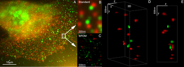
3D dual color super resolution microscopy with Her2 and Her3 in breast cells, standard dyes: Alexa 488, Alexa 568 LIMON
 
SPDM (spectral precision distance microscopy), the basic localization microscopy technology is a light optical process of fluorescence microscopy which allows position, distance and angle measurements on "optically isolated" particles (e.g. molecules) well below the theoretical limit of resolution for light microscopy. "Optically isolated" means that at a given point in time, only a single particle/molecule within a region of a size determined by conventional optical resolution (typically approx. 200–250 nm diameter) is being registered. This is possible when molecules within such a region all carry different spectral markers (e.g. different colors or other usable differences in the light emission of different particles).

Many standard fluorescent dyes like GFP, Alexa dyes, Atto dyes, Cy2/Cy3 and fluorescein molecules can be used for localization microscopy, provided certain photo-physical conditions are present. Using this so-called SPDMphymod (physically modifiable fluorophores) technology a single laser wavelength of suitable intensity is sufficient for nanoimaging.

3D super resolution microscopy

3D super resolution microscopy with standard fluorescent dyes can be achieved by combination of localization microscopy for standard fluorescent dyes SPDMphymod and structured illumination SMI.

STED

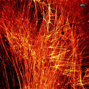
Stimulated emission depletion (STED) microscopy image of actin filaments within a cell.
 
Stimulated emission depletion is a simple example of how higher resolution surpassing the diffraction limit is possible, but it has major limitations. STED is a fluorescence microscopy technique which uses a combination of light pulses to induce fluorescence in a small sub-population of fluorescent molecules in a sample. Each molecule produces a diffraction-limited spot of light in the image, and the centre of each of these spots corresponds to the location of the molecule. As the number of fluorescing molecules is low the spots of light are unlikely to overlap and therefore can be placed accurately. This process is then repeated many times to generate the image. Stefan Hell of the Max Planck Institute for Biophysical Chemistry was awarded the 10th German Future Prize in 2006 and Nobel Prize for Chemistry in 2014 for his development of the STED microscope and associated methodologies.

Alternatives

In order to overcome the limitations set by the diffraction limit of visible light other microscopes have been designed which use other waves.
It is important to note that higher frequency waves have limited interaction with matter, for example soft tissues are relatively transparent to X-rays resulting in distinct sources of contrast and different target applications. 

The use of electrons and X-rays in place of light allows much higher resolution – the wavelength of the radiation is shorter so the diffraction limit is lower. To make the short-wavelength probe non-destructive, the atomic beam imaging system (atomic nanoscope) has been proposed and widely discussed in the literature, but it is not yet competitive with conventional imaging systems. 

STM and AFM are scanning probe techniques using a small probe which is scanned over the sample surface. Resolution in these cases is limited by the size of the probe; micromachining techniques can produce probes with tip radii of 5–10 nm. 

Additionally, methods such as electron or X-ray microscopy use a vacuum or partial vacuum, which limits their use for live and biological samples (with the exception of an environmental scanning electron microscope). The specimen chambers needed for all such instruments also limits sample size, and sample manipulation is more difficult. Color cannot be seen in images made by these methods, so some information is lost. They are however, essential when investigating molecular or atomic effects, such as age hardening in aluminium alloys, or the microstructure of polymers.

Refracting telescope

From Wikipedia, the free encyclopedia

Image of a refracting telescope from the Cincinnati Observatory in 1848

A refracting telescope (also called a refractor) is a type of optical telescope that uses a lens as its objective to form an image (also referred to a dioptric telescope). The refracting telescope design was originally used in spy glasses and astronomical telescopes but is also used for long focus camera lenses. Although large refracting telescopes were very popular in the second half of the 19th century, for most research purposes the refracting telescope has been superseded by the reflecting telescope which allows larger apertures. A refractor's magnification is calculated by dividing the focal length of the objective lens by that of the eyepiece.

Invention

Refractors were the earliest type of optical telescope. The first practical refracting telescopes appeared in the Netherlands about 1608, and were credited to three individuals, Hans Lippershey and Zacharias Janssen, spectacle-makers in Middelburg, and Jacob Metius of Alkmaar. Galileo Galilei, happening to be in Venice in about the month of May 1609, heard of the invention and constructed a version of his own. Galileo then communicated the details of his invention to the public, and presented the instrument itself to the Doge Leonardo Donato, sitting in full council.

Refracting telescope designs

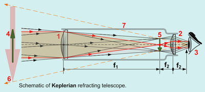
Kepschem.png
All refracting telescopes use the same principles. The combination of an objective lens 1 and some type of eyepiece 2 is used to gather more light than the human eye is able to collect on its own, focus it 5, and present the viewer with a brighter, clearer, and magnified virtual image 6

The objective in a refracting telescope refracts or bends light. This refraction causes parallel light rays to converge at a focal point; while those not parallel converge upon a focal plane. The telescope converts a bundle of parallel rays to make an angle α, with the optical axis to a second parallel bundle with angle β. The ratio β/α is called the angular magnification. It equals the ratio between the retinal image sizes obtained with and without the telescope.

Refracting telescopes can come in many different configurations to correct for image orientation and types of aberration. Because the image was formed by the bending of light, or refraction, these telescopes are called refracting telescopes or refractors.

Galileo's telescope

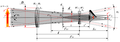
Optical diagram of Galilean telescope y – Distant object ; y′ – Real image from objective ; y″ – Magnified virtual image from eyepiece ; D – Entrance pupil diameter ; d – Virtual exit pupil diameter ; L1 – Objective lens ; L2 – Eyepiece lens e – Virtual exit pupil – Telescope equals 
 
The design Galileo Galilei used in 1609 is commonly called a Galilean telescope. It used a convergent (plano-convex) objective lens and a divergent (plano-concave) eyepiece lens (Galileo, 1610). A Galilean telescope, because the design has no intermediary focus, results in a non-inverted and upright image. 

Galileo’s best telescope magnified objects about 30 times. Because of flaws in its design, such as the shape of the lens and the narrow field of view, the images were blurry and distorted. Despite these flaws, the telescope was still good enough for Galileo to explore the sky. The Galilean telescope could view the phases of Venus, and was able to see craters on the Moon and four moons orbiting Jupiter. 

Parallel rays of light from a distant object (y) would be brought to a focus in the focal plane of the objective lens (F′ L1 / y′). The (diverging) eyepiece (L2) lens intercepts these rays and renders them parallel once more. Non-parallel rays of light from the object traveling at an angle α1 to the optical axis travel at a larger angle (α2 > α1) after they passed through the eyepiece. This leads to an increase in the apparent angular size and is responsible for the perceived magnification.

The final image (y″) is a virtual image, located at infinity and is the same way up as the object.

Keplerian telescope

Woodcut illustration of a 46 m (150 ft) focal length Keplerian astronomical refracting telescope built by Johannes Hevelius.
 
The Keplerian telescope, invented by Johannes Kepler in 1611, is an improvement on Galileo's design. It uses a convex lens as the eyepiece instead of Galileo's concave one. The advantage of this arrangement is that the rays of light emerging from the eyepiece are converging. This allows for a much wider field of view and greater eye relief, but the image for the viewer is inverted. Considerably higher magnifications can be reached with this design, but to overcome aberrations the simple objective lens needs to have a very high f-ratio (Johannes Hevelius built one with a 46-metre (150 ft) focal length, and even longer tubeless "aerial telescopes" were constructed). The design also allows for use of a micrometer at the focal plane (used to determine the angular size and/or distance between objects observed).

Achromatic refractors

The achromatic refracting lens was invented in 1733 by an English barrister named Chester Moore Hall, although it was independently invented and patented by John Dollond around 1758. The design overcame the need for very long focal lengths in refracting telescopes by using an objective made of two pieces of glass with different dispersion, 'crown' and 'flint glass', to limit the effects of chromatic and spherical aberration. Each side of each piece is ground and polished, and then the two pieces are assembled together. Achromatic lenses are corrected to bring two wavelengths (typically red and blue) into focus in the same plane. The era of the 'great refractors' in the 19th century saw large achromatic lenses culminating with the largest achromatic refractor ever built, the Great Paris Exhibition Telescope of 1900.

Apochromatic refractors

Apochromatic refractors have objectives built with special, extra-low dispersion materials. They are designed to bring three wavelengths (typically red, green, and blue) into focus in the same plane. The residual color error (tertiary spectrum) can be up to an order of magnitude less than that of an achromatic lens. Such telescopes contain elements of fluorite or special, extra-low dispersion (ED) glass in the objective and produce a very crisp image that is virtually free of chromatic aberration. Due to the special materials needed in the fabrication, apochromatic refractors are usually more expensive than telescopes of other types with a comparable aperture.

Technical considerations

The 1.0-meter (40 in) refractor, at Yerkes Observatory, the largest achromatic refractor ever put into astronomical use
 
Refractors suffer from residual chromatic and spherical aberration. This affects shorter focal ratios more than longer ones. A 100 mm (4 in) f/6 achromatic refractor is likely to show considerable color fringing (generally a purple halo around bright objects). A 100 mm (4 in) f/16 has little color fringing. 

In very large apertures, there is also a problem of lens sagging, a result of gravity deforming glass. Since a lens can only be held in place by its edge, the center of a large lens sags due to gravity, distorting the images it produces. The largest practical lens size in a refracting telescope is around 1 meter (39 in).

There is a further problem of glass defects, striae or small air bubbles trapped within the glass. In addition, glass is opaque to certain wavelengths, and even visible light is dimmed by reflection and absorption when it crosses the air-glass interfaces and passes through the glass itself. Most of these problems are avoided or diminished in reflecting telescopes, which can be made in far larger apertures and which have all but replaced refractors for astronomical research.

List of the largest refracting telescopes

A list of the largest refracting telescopes over 60 cm (24 in) diameter.

Introduction to entropy

From Wikipedia, the free encyclopedia https://en.wikipedia.org/wiki/Introduct...