Search This Blog

Monday, August 5, 2024

Photovoltaic thermal hybrid solar collector

Schematic cross section of an uncovered PVT collector with sheet-and-tube type heat exchanger and rear insulation:
1 - Anti-reflective glass
2 - Encapsulant (e.g. EVA)
3 - Solar PV cells
4 - Encapsulant (e.g. EVA)
5 - Backsheet (e.g. PVF)
6 - Heat exchanger (e.g. aluminum, copper or polymers)
7 - Thermal insulation (e.g. mineral wool, polyurethane)

Photovoltaic thermal collectors, typically abbreviated as PVT collectors and also known as hybrid solar collectors, photovoltaic thermal solar collectors, PV/T collectors or solar cogeneration systems, are power generation technologies that convert solar radiation into usable thermal and electrical energy. PVT collectors combine photovoltaic solar cells (often arranged in solar panels), which convert sunlight into electricity, with a solar thermal collector, which transfers the otherwise unused waste heat from the PV module to a heat transfer fluid. By combining electricity and heat generation within the same component, these technologies can reach a higher overall efficiency than solar photovoltaic (PV) or solar thermal (T) alone.

Significant research has gone into developing a diverse range of PVT technologies since the 1970s. The different PVT collector technologies differ substantially in their collector design and heat transfer fluid and address different applications ranging from low temperature heat below ambient up to high temperature heat above 100 °C.

PVT markets

PVT collectors generate solar heat and electricity basically free of direct CO2 emissions and are therefore regarded as a promising green technology to supply renewable electricity and heat to buildings and industrial processes.

Heat is the largest energy end-use. In 2015, the provision of heating for use in buildings, industrial purposes and other applications accounted for around 52% (205 EJ) of the total energy consumed. Of this, over half was used in the industry and around 46% in the building sector. While 72% of the heat was provided by the direct combustion of fossil fuels, only 7% was from modern renewables such as solar thermal, biofuel or geothermal energy. The low-grade heat market up to 150 °C is estimated to be 26.8% of the worldwide final energy demand, which is currently serviced by fossil fuels (gas, oil, and coal), electricity and renewable heat. This is the sum of industry demand 7.1% (25.5 EJ) and building demand 19.7% (49.0 EJ residential and 13.6 EJ commercial).

The electricity demand in buildings and industry is expected to grow further due to ongoing electrification and sector coupling. For a significant reduction of greenhouse gas emissions, it is essential that the major share of electricity is sourced from renewable energy sources, such as wind power, solar energy, biomass and water power.

The market for renewable heat and electricity is therefore vast, illustrating the market potential of PVT collectors.

The report "Solar Heat Worldwide" assessed the global market of PVT collectors in 2019. According to the authors, the total area of installed collectors amounted to 1.16 million square meters. Uncovered water collectors had the largest market share (55%), followed by air collectors (43%) and covered water collectors (2%). The country with the largest installed capacity was France (42%), followed by South Korea (24%), China (11%) and Germany (10%).

PVT collector technology

PVT collectors combine the generation of solar electricity and heat in a single component, and thus achieve a higher overall efficiency and better utilization of the solar spectrum than conventional PV modules.

Utilization of solar spectrum of a PVT collector

Photovoltaic cells typically reach an electrical efficiency between 15% and 20%, while the largest share of the solar spectrum (65% - 70%) is converted into heat, increasing the temperature of PV modules. PVT collectors, on the contrary, are engineered to transfer heat from the PV cells to a fluid, thereby cooling the cells and thus improving their efficiency. In this way, this excess heat is made useful and can be utilized to heat water or as a low temperature source for heat pumps, for example. Thus, PVT collectors make better use of the solar spectrum.

Most photovoltaic cells (e.g. silicon based) suffer from a drop in efficiency with increased cell temperatures. Each Kelvin of increased cell temperature reduces the efficiency by 0.2 – 0.5%. Therefore, heat removal from the PV cells can lower their temperature and thus increase the cells' efficiency. Improved PV cell lifetimes are another benefit of lower operation temperatures.

This is an effective method to maximize total system efficiency and reliability, but causes the thermal component to under-perform as compared to that achievable with a pure solar thermal collector. That is to say, the maximum operating temperatures for most PVT system are limited to less than the maximum cell temperature (typically below 100 °C). Nevertheless, two or more units of heat energy are still generated for each unit of electrical energy, depending on cell efficiency and system design.

Types of PVT collectors

There are a multitude of technical possibilities to combine PV cells and solar thermal collectors. A number of PVT collectors are available as commercial products, which can be divided into the following categories according to their basic design and heat transfer fluid:

  • PVT liquid collector
  • PVT air collector

In addition to the classification by heat transfer fluid, PVT collectors can also be categorized according to the presence of a secondary glazing to reduce heat losses and the presence of a device to concentrate solar irradiation:

  • Uncovered PVT collector (WISC PVT)
  • Covered PVT collector
  • Concentrating PVT collector (CPVT)

Moreover, PVT collectors can be classified according to their design, such as cell technology, type of fluid, heat exchanger material and geometry, type of contact between fluid and PV module, fixation of heat exchanger, or level of building integration (building integrated PVT (BIPVT) collectors).

The design and type of PVT collectors always implies a certain adaption to operating temperatures, applications, and giving priority to either heat or electricity generation. For instance, operating the PVT collector at low temperatures leads to a cooling effect of PV cells compared to PV modules and therefore results in an increase of electric power. However, the heat also has to be utilized at low temperatures.

The maximum operating temperatures for most PV modules are limited to less than the maximum certified operation temperatures (typically 85 °C). Nevertheless, two or more units of thermal energy are generated for each unit of electrical energy, depending on cell efficiency and system design.

PVT liquid collector

The basic water-cooled design uses channels to direct fluid flow using piping attached directly or indirectly to the back of a PV module. In a standard fluid-based system, a working fluid, typically water, glycol or mineral oil circulates in the heat exchanger behind the PV cells. The heat from the PV cells is conducted through the metal and absorbed by the working fluid (presuming that the working fluid is cooler than the operating temperature of the cells).

PVT air collector

The basic air-cooled design uses either a hollow, conductive housing to mount the photovoltaic panels or a controlled flow of air to the rear face of the PV panel. PVT air collectors either draw in fresh outside air or use air as a circulating heat transfer medium in a closed loop. Heat is radiated from the panels into the enclosed space, where the air is either circulated into a building HVAC system to recapture heat energy, or rises and is vented from the top of the structure. The heat transfer capability of air is lower than that of typically used liquids and therefore requires a proportionally higher mass flow rate than an equivalent PVT liquid collector. The advantage is that the infrastructure required has lower cost and complexity.

The heated air is circulated into a building HVAC system to deliver thermal energy. Excess heat generated can be simply vented to the atmosphere. Some versions of the PVT air collector can be operated in a way to cool the PV panels to generate more electricity and assist with reducing thermal effects on lifetime performance degradation.

A number of different configurations of PVT air collectors exist, which vary in engineering sophistication. PVT air collector configurations range from a basic enclosed shallow metal box with an intake and exhaust up to optimized heat transfer surfaces that achieve uniform panel heat transfer across a wide range of process and ambient conditions.

PVT air collectors can be carried out as uncovered or covered designs.

Uncovered PVT collector (WISC)

Uncovered PVT collectors, also denoted as unglazed or wind and/or infrared sensitive PVT collectors (WISC), typically consist of a PV module with a heat exchanger structure attached to the back of the PV module. Despite their name, the solar cells are generally attached to the back side of a front glass and thus covered by it, but without an air gap. While most PVT collectors are prefabricated units, some products are offered as heat exchangers to be retrofitted to off-the-shelf PV modules. In both cases, a good and longtime durable thermal contact with a high heat transfer coefficient between the PV cells and the fluid is essential.

The rear side of the uncovered PVT collector can be equipped with thermal insulation (e.g. mineral wool or foam) to reduce heat losses of the heated fluid. Uninsulated PVT collectors are beneficial for operation near and below ambient temperatures. Particularly uncovered PVT collectors with increased heat transfer to ambient air are a suitable heat source for heat pump systems. When the temperature in the heat pump's source is lower than the ambient, the fluid can be heated up to ambient temperature even in periods without sunshine.

Accordingly, uncovered PVT collectors can be categorized into:

  • Uncovered PVT collector with increased heat transfer to ambient air
  • Uncovered PVT collector without rear insulation
  • Uncovered PVT collector with rear insulation

Uncovered PVT collectors are also used to provide renewable cooling by dissipating heat via the PVT collector to the ambient air or by utilizing the radiative cooling effect. In doing so, cold air or water is harnessed, which can be utilized for HVAC applications.

Covered PVT collector

Covered, or glazed PVT collectors, feature an additional glazing, which encloses an insulating air layer between the PV module and the secondary glazing. This reduces heat losses and increases the thermal efficiency. Moreover, covered PVT collectors can reach significantly higher temperatures than PV modules or uncovered PVT collectors. The operating temperatures mostly depend on the temperature of the working fluid. The average fluid temperature can be between 25 °C in swimming pool applications to 90 °C in solar cooling systems.

Covered PVT collectors resemble the form and design of conventional flat plate collectors or evacuated vacuum tubes. Yet, PV cells instead of spectrally-selective absorber coatings absorb the incident solar irradiance and generate an electrical current in addition to solar heat.

The insulating characteristics of the front cover increase the thermal efficiency and allow for higher operating temperatures. However, the additional optical interfaces increase optical reflections and thus reduce the generated electrical power. Anti-reflective coatings on the front glazing can reduce the additional optical losses.

PVT concentrator (CPVT)

A concentrator system has the advantage to reduce the amount of PV cells needed. Therefore, it is possible to use more expensive and efficient PV cells, e.g. multi-junction photovoltaic cell. The concentration of sunlight also reduces the amount of hot PV-absorber area and therefore reduces heat losses to the ambient, which improves significantly the efficiency for higher application temperatures.

Concentrator systems also often require reliable control systems to accurately track the Sun and to protect the PV cells from damaging over-temperature conditions. However, there are also stationery PVT collector types that use nonimaging reflectors, such as the Compound Parabolic Concentrator (CPC), and do not have to track the Sun.

Under ideal conditions, about 75% of the Sun's power directly incident upon such systems can be gathered as electricity and heat at temperatures up to 160 °C. CPVT units that are coupled with thermal energy storage and organic Rankine cycle generators can provide on-demand recovery of up to 70% of their instantaneous electricity generation, and may thus be a fairly efficient alternative to the types of electrical storage which are joined with traditional PV systems.

A limitation of high-concentrator (i.e. HCPV and HCPVT) systems is that they maintain their long-term advantages over conventional c-Si/mc-Si collectors only in regions that remain consistently free of atmospheric aerosol contaminants (e.g. light clouds, smog, etc.). Power production is rapidly degraded because 1) radiation is reflected and scattered outside of the small (often less than 1°-2°) acceptance angle of the collection optics, and 2) absorption of specific components of the solar spectrum causes one or more series junctions within the multi-junction cells to under-perform. The short-term impacts of such power generation irregularities can be reduced to some degree with inclusion of electrical and thermal storage in the system.

PVT applications

The range of applications of PVT collectors, and in general solar thermal collectors, can be divided according to their temperature levels:
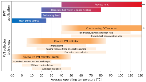
Map of PVT collector technologies and PVT applications per operating temperature
  • low temperature applications up to 50 °C
  • medium temperature applications up to 80 °C
  • high temperature applications above 80 °C

Accordingly, PVT collector technologies can be clustered with respect to their temperature levels: the suitability per temperature range depends on the PVT collector design and technology. Therefore, each PVT collector technology features different optimal temperature ranges. The operating temperature ultimately defines which type of PVT collector is suitable for which application.

Low temperature applications include heat pump systems and heating swimming pools or spas up to 50 °C. PVT collectors in heat pump systems act either as low temperature source for the heat pump evaporator or on the load side to supply medium temperature heat to a storage tank. Moreover, regeneration of boreholes and ground source heat exchangers is possible. Uncovered PVT collectors with enhanced air-to-water heat exchange can even be the only source of a heat pump system. In combination with a system architecture allowing to store cold produced with WISC or air collectors also air conditioning is possible.

Low and medium temperature applications for space heating and water heating are found in buildings, with temperatures from 20 °C to 80 °C. The temperatures of the specific system depend on the requirements of the heat supply system for domestic hot water (e.g. freshwater station, temperature requirements for legionella prevention) and for space heating (e.g. underfloor heating, radiators). Moreover, the PVT collector array can be dimensioned to cover only smaller fractions of the heat demand (e.g. hot water pre-heating), thus reducing operating temperatures of the PVT collector.

Solar process heat includes a diverse range of industrial applications with low to high temperature requirements (e.g. solar water desalination, solar cooling, or power generation with concentrating PVT collectors).

Depending on the type of heat transfer fluid, PVT collector technologies are suited for several applications:

PVT technologies can bring a valuable contribution to the world's energy mix and can be considered as an option for applications delivering renewable electricity, heat or cold.

Schwarzschild radius

From Wikipedia, the free encyclopedia
https://en.wikipedia.org/wiki/Schwarzschild_radius

The Schwarzschild radius or the gravitational radius is a physical parameter in the Schwarzschild solution to Einstein's field equations that corresponds to the radius defining the event horizon of a Schwarzschild black hole. It is a characteristic radius associated with any quantity of mass. The Schwarzschild radius was named after the German astronomer Karl Schwarzschild, who calculated this exact solution for the theory of general relativity in 1916.

The Schwarzschild radius is given as where G is the gravitational constant, M is the object mass, and c is the speed of light.

History

In 1916, Karl Schwarzschild obtained the exact solution to Einstein's field equations for the gravitational field outside a non-rotating, spherically symmetric body with mass (see Schwarzschild metric). The solution contained terms of the form and , which becomes singular at and respectively. The has come to be known as the Schwarzschild radius. The physical significance of these singularities was debated for decades. It was found that the one at is a coordinate singularity, meaning that it is an artifact of the particular system of coordinates that was used; while the one at is a spacetime singularity and cannot be removed. The Schwarzschild radius is nonetheless a physically relevant quantity, as noted above and below.

This expression had previously been calculated, using Newtonian mechanics, as the radius of a spherically symmetric body at which the escape velocity was equal to the speed of light. It had been identified in the 18th century by John Michell and Pierre-Simon Laplace.

Parameters

The Schwarzschild radius of an object is proportional to its mass. Accordingly, the Sun has a Schwarzschild radius of approximately 3.0 km (1.9 mi), whereas Earth's is approximately 9 mm (0.35 in) and the Moon's is approximately 0.1 mm (0.0039 in).

Derivation

Black hole classification by Schwarzschild radius

Black hole classifications
Class Approx.
mass
Approx.
radius
Supermassive black hole 105–1010 MSun 0.001–400 AU
Intermediate-mass black hole 103 MSun 103 km ≈ REarth
Stellar black hole 10 MSun 30 km
Micro black hole up to MMoon up to 0.1 mm

Any object whose radius is smaller than its Schwarzschild radius is called a black hole. The surface at the Schwarzschild radius acts as an event horizon in a non-rotating body (a rotating black hole operates slightly differently). Neither light nor particles can escape through this surface from the region inside, hence the name "black hole".

Black holes can be classified based on their Schwarzschild radius, or equivalently, by their density, where density is defined as mass of a black hole divided by the volume of its Schwarzschild sphere. As the Schwarzschild radius is linearly related to mass, while the enclosed volume corresponds to the third power of the radius, small black holes are therefore much more dense than large ones. The volume enclosed in the event horizon of the most massive black holes has an average density lower than main sequence stars.

Supermassive black hole

A supermassive black hole (SMBH) is the largest type of black hole, though there are few official criteria on how such an object is considered so, on the order of hundreds of thousands to billions of solar masses. (Supermassive black holes up to 21 billion (2.1 × 10¹⁰M have been detected, such as NGC 4889.) Unlike stellar mass black holes, supermassive black holes have comparatively low average densities. (Note that a (non-rotating) black hole is a spherical region in space that surrounds the singularity at its center; it is not the singularity itself.) With that in mind, the average density of a supermassive black hole can be less than the density of water.

The Schwarzschild radius of a body is proportional to its mass and therefore to its volume, assuming that the body has a constant mass-density. In contrast, the physical radius of the body is proportional to the cube root of its volume. Therefore, as the body accumulates matter at a given fixed density (in this example, 997 kg/m3, the density of water), its Schwarzschild radius will increase more quickly than its physical radius. When a body of this density has grown to around 136 million solar masses (1.36 × 108 M), its physical radius would be overtaken by its Schwarzschild radius, and thus it would form a supermassive black hole.

It is thought that supermassive black holes like these do not form immediately from the singular collapse of a cluster of stars. Instead they may begin life as smaller, stellar-sized black holes and grow larger by the accretion of matter, or even of other black holes.

The Schwarzschild radius of the supermassive black hole at the Galactic Center of the Milky Way is approximately 12 million kilometres. Its mass is about 4.1 million M.

Stellar black hole

Stellar black holes have much greater average densities than supermassive black holes. If one accumulates matter at nuclear density (the density of the nucleus of an atom, about 1018 kg/m3; neutron stars also reach this density), such an accumulation would fall within its own Schwarzschild radius at about 3 M and thus would be a stellar black hole.

Micro black hole

A small mass has an extremely small Schwarzschild radius. A black hole of mass similar to that of Mount Everest would have a Schwarzschild radius much smaller than a nanometre. Its average density at that size would be so high that no known mechanism could form such extremely compact objects. Such black holes might possibly be formed in an early stage of the evolution of the universe, just after the Big Bang, when densities of matter were extremely high. Therefore, these hypothetical miniature black holes are called primordial black holes.

Other uses

In gravitational time dilation

Gravitational time dilation near a large, slowly rotating, nearly spherical body, such as the Earth or Sun can be reasonably approximated as follows: where:

  • tr is the elapsed time for an observer at radial coordinate r within the gravitational field;
  • t is the elapsed time for an observer distant from the massive object (and therefore outside of the gravitational field);
  • r is the radial coordinate of the observer (which is analogous to the classical distance from the center of the object);
  • rs is the Schwarzschild radius.

Compton wavelength intersection

The Schwarzschild radius () and the Compton wavelength () corresponding to a given mass are similar when the mass is around one Planck mass (), when both are of the same order as the Planck length ().

Calculating the maximum volume and radius possible given a density before a black hole forms

The Schwarzschild radius equation can be manipulated to yield an expression that gives the largest possible radius from an input density that doesn't form a black hole. Taking the input density as ρ,

For example, the density of water is 1000 kg/m3. This means the largest amount of water you can have without forming a black hole would have a radius of 400 920 754 km (about 2.67 AU).

Solar cell research

From Wikipedia, the free encyclopedia
https://en.wikipedia.org/wiki/Solar_cell_research

Reported timeline of research solar cell energy conversion efficiencies since 1976 (National Renewable Energy Laboratory)

There are currently many research groups active in the field of photovoltaics in universities and research institutions around the world. This research can be categorized into three areas: making current technology solar cells cheaper and/or more efficient to effectively compete with other energy sources; developing new technologies based on new solar cell architectural designs; and developing new materials to serve as more efficient energy converters from light energy into electric current or light absorbers and charge carriers.

Silicon processing

One way of reducing the cost is to develop cheaper methods of obtaining silicon that is sufficiently pure. Silicon is a very common element, but is normally bound in silica, or silica sand. Processing silica (SiO2) to produce silicon is a very high energy process - at current efficiencies, it takes one to two years for a conventional solar cell to generate as much energy as was used to make the silicon it contains. More energy efficient methods of synthesis are not only beneficial to the solar industry, but also to industries surrounding silicon technology as a whole.

The current industrial production of silicon is via the reaction between carbon (charcoal) and silica at a temperature around 1700 °C. In this process, known as carbothermic reduction, each tonne of silicon (metallurgical grade, about 98% pure) is produced with the emission of about 1.5 tonnes of carbon dioxide.

Solid silica can be directly converted (reduced) to pure silicon by electrolysis in a molten salt bath at a fairly mild temperature (800 to 900 °C). While this new process is in principle the same as the FFC Cambridge Process which was first discovered in late 1996, the interesting laboratory finding is that such electrolytic silicon is in the form of porous silicon which turns readily into a fine powder, with a particle size of a few micrometers, and may therefore offer new opportunities for development of solar cell technologies.

Another approach is also to reduce the amount of silicon used and thus cost, is by micromachining wafers into very thin, virtually transparent layers that could be used as transparent architectural coverings. The technique involves taking a silicon wafer, typically 1 to 2 mm thick, and making a multitude of parallel, transverse slices across the wafer, creating a large number of slivers that have a thickness of 50 micrometres and a width equal to the thickness of the original wafer. These slices are rotated 90 degrees, so that the surfaces corresponding to the faces of the original wafer become the edges of the slivers. The result is to convert, for example, a 150 mm diameter, 2 mm-thick wafer having an exposed silicon surface area of about 175 cm2 per side into about 1000 slivers having dimensions of 100 mm × 2 mm × 0.1 mm, yielding a total exposed silicon surface area of about 2000 cm2 per side. As a result of this rotation, the electrical doping and contacts that were on the face of the wafer are located at the edges of the sliver, rather than at the front and rear as in the case of conventional wafer cells. This has the interesting effect of making the cell sensitive from both the front and rear of the cell (a property known as bifaciality). Using this technique, one silicon wafer is enough to build a 140 watt panel, compared to about 60 wafers needed for conventional modules of same power output.

Nanocrystalline solar cells

These structures make use of some of the same thin-film light absorbing materials but are overlain as an extremely thin absorber on a supporting matrix of conductive polymer or mesoporous metal oxide having a very high surface area to increase internal reflections (and hence increase the probability of light absorption). Using nanocrystals allows one to design architectures on the length scale of nanometers, the typical exciton diffusion length. In particular, single-nanocrystal ('channel') devices, an array of single p-n junctions between the electrodes and separated by a period of about a diffusion length, represent a new architecture for solar cells and potentially high efficiency.

Thin-film processing

Thin-film photovoltaic cells can use less than 1% of the expensive raw material (silicon or other light absorbers) compared to wafer-based solar cells, leading to a significant price drop per Watt peak capacity. There are many research groups around the world actively researching different thin-film approaches and/or materials.

One particularly promising technology is crystalline silicon thin films on glass substrates. This technology combines the advantages of crystalline silicon as a solar cell material (abundance, non-toxicity, high efficiency, long-term stability) with the cost savings of using a thin-film approach.

Another interesting aspect of thin-film solar cells is the possibility to deposit the cells on all kind of materials, including flexible substrates (PET for example), which opens a new dimension for new applications.

Metamorphic multijunction solar cell

As of December 2014, the world record for solar cell efficiency at 46% was achieved by using multi-junction concentrator solar cells, developed from collaboration efforts of Soitec, CEA-Leti, France together with Fraunhofer ISE, Germany.

The National Renewable Energy Laboratory (NREL) won one of R&D Magazine's R&D 100 Awards for its Metamorphic Multijunction photovoltaic cell, an ultra-light and flexible cell that converts solar energy with record efficiency.

The ultra-light, highly efficient solar cell was developed at NREL and is being commercialized by Emcore Corp. of Albuquerque, N.M., in partnership with the Air Force Research Laboratories Space Vehicles Directorate at Kirtland Air Force Base in Albuquerque.

It represents a new class of solar cells with clear advantages in performance, engineering design, operation and cost. For decades, conventional cells have featured wafers of semiconducting materials with similar crystalline structure. Their performance and cost effectiveness is constrained by growing the cells in an upright configuration. Meanwhile, the cells are rigid, heavy and thick with a bottom layer made of germanium.

In the new method, the cell is grown upside down. These layers use high-energy materials with extremely high quality crystals, especially in the upper layers of the cell where most of the power is produced. Not all of the layers follow the lattice pattern of even atomic spacing. Instead, the cell includes a full range of atomic spacing, which allows for greater absorption and use of sunlight. The thick, rigid germanium layer is removed, reducing the cell's cost and 94% of its weight. By turning the conventional approach to cells on its head, the result is an ultra-light and flexible cell that also converts solar energy with record efficiency (40.8% under 326 suns concentration).

Polymer processing

The invention of conductive polymers (for which Alan Heeger, Alan G. MacDiarmid and Hideki Shirakawa were awarded a Nobel prize) may lead to the development of much cheaper cells that are based on inexpensive plastics. However, organic solar cells generally suffer from degradation upon exposure to UV light, and hence have lifetimes which are far too short to be viable. The bonds in the polymers, are always susceptible to breaking up when radiated with shorter wavelengths. Additionally, the conjugated double bond systems in the polymers which carry the charge, react more readily with light and oxygen. So most conductive polymers, being highly unsaturated and reactive, are highly sensitive to atmospheric moisture and oxidation, making commercial applications difficult.

Nanoparticle processing

Experimental non-silicon solar panels can be made of quantum heterostructures, e.g. carbon nanotubes or quantum dots, embedded in conductive polymers or mesoporous metal oxides. In addition, thin films of many of these materials on conventional silicon solar cells can increase the optical coupling efficiency into the silicon cell, thus boosting the overall efficiency. By varying the size of the quantum dots, the cells can be tuned to absorb different wavelengths. Although the research is still in its infancy, quantum dot modified photovoltaics may be able to achieve up to 42% energy conversion efficiency due to multiple exciton generation (MEG).

MIT researchers have found a way of using a virus to improve solar cell efficiency by a third.

Transparent conductors

Many new solar cells use transparent thin films that are also conductors of electrical charge. The dominant conductive thin films used in research now are transparent conductive oxides (abbreviated "TCO"), and include fluorine-doped tin oxide (SnO2:F, or "FTO"), doped zinc oxide (e.g.: ZnO:Al), and indium tin oxide (abbreviated "ITO"). These conductive films are also used in the LCD industry for flat panel displays. The dual function of a TCO allows light to pass through a substrate window to the active light-absorbing material beneath, and also serves as an ohmic contact to transport photogenerated charge carriers away from that light-absorbing material. The present TCO materials are effective for research, but perhaps are not yet optimized for large-scale photovoltaic production. They require very special deposition conditions at high vacuum, they can sometimes suffer from poor mechanical strength, and most have poor transmittance in the infrared portion of the spectrum (e.g.: ITO thin films can also be used as infrared filters in airplane windows). These factors make large-scale manufacturing more costly.

A relatively new area has emerged using carbon nanotube networks as a transparent conductor for organic solar cells. Nanotube networks are flexible and can be deposited on surfaces a variety of ways. With some treatment, nanotube films can be highly transparent in the infrared, possibly enabling efficient low-bandgap solar cells. Nanotube networks are p-type conductors, whereas traditional transparent conductors are exclusively n-type. The availability of a p-type transparent conductor could lead to new cell designs that simplify manufacturing and improve efficiency.

Silicon wafer-based solar cells

Despite the numerous attempts at making better solar cells by using new and exotic materials, the reality is that the photovoltaics market is still dominated by silicon wafer-based solar cells (first-generation solar cells). This means that most solar cell manufacturers are currently equipped to produce this type of solar cells. Consequently, a large body of research is being done all over the world to manufacture silicon wafer-based solar cells at lower cost and to increase the conversion efficiencies without an exorbitant increase in production cost. The ultimate goal for both wafer-based and alternative photovoltaic concepts is to produce solar electricity at a cost comparable to currently market-dominant coal, natural gas, and nuclear power in order to make it the leading primary energy source. To achieve this it may be necessary to reduce the cost of installed solar systems from currently about US$1.80 (for bulk Si technologies) to about US$0.50 per Watt peak power. Since a major part of the final cost of a traditional bulk silicon module is related to the high cost of solar grade polysilicon feedstock (about US$0.4/Watt peak) there exists substantial drive to make Si solar cells thinner (material savings) or to make solar cells from cheaper upgraded metallurgical silicon (so called "dirty Si").

IBM has a semiconductor wafer reclamation process that uses a specialized pattern removal technique to repurpose scrap semiconductor wafers to a form used to manufacture silicon-based solar panels. The new process was recently awarded the “2007 Most Valuable Pollution Prevention Award” from The National Pollution Prevention Roundtable (NPPR).

Infrared solar cells

Researchers at Idaho National Laboratory, along with partners at Lightwave Power Inc. in Cambridge, MA and Patrick Pinhero of the University of Missouri, have devised an inexpensive way to produce plastic sheets containing billions of nanoantennas that collect heat energy generated by the sun and other sources, which garnered two 2007 Nano50 awards. The company ceased operations in 2010. While methods to convert the energy into usable electricity still need to be developed, the sheets could one day be manufactured as lightweight "skins" that power everything from hybrid cars to computers and mobile phones with higher efficiency than traditional solar cells. The nanoantennas target mid-infrared rays, which the Earth continuously radiates as heat after absorbing energy from the sun during the day; also double-sided nanoantenna sheets can harvest energy from different parts of the Sun's spectrum. In contrast, traditional solar cells can only use visible light, rendering them idle after dark.

Since 2012 the group of Roberto Germano at Promete s.r.l. in Naples, Italy, is working on the Oxhydroelectric effect, which generates voltage and electric current in pure liquid water, after creating a physical (not chemical) asymmetry in the liquid water e.g. thanks to a strongly hydrophile polymer, such as Nafion.

UV solar cells

Japan's National Institute of Advanced Industrial Science and Technology (AIST) has succeeded in developing a transparent solar cell that uses ultraviolet (UV) light to generate electricity but allows visible light to pass through it. Most conventional solar cells use visible and infrared light to generate electricity. Used to replace conventional window glass, the installation surface area could be large, leading to potential uses that take advantage of the combined functions of power generation, lighting and temperature control.

This transparent, UV-absorbing system was achieved by using an organic-inorganic heterostructure made of the p-type semiconducting polymer PEDOT:PSS film deposited on a Nb-doped strontium titanate substrate. PEDOT:PSS is easily fabricated into thin films due to its stability in air and its solubility in water. These solar cells are only activated in the UV region and result in a relatively high quantum yield of 16% electron/photon. Future work in this technology involves replacing the strontium titanate substrate with a strontium titanate film deposited on a glass substrate in order to achieve a low-cost, large-area manufacture.

Since then, other methods have been discovered to include the UV wavelengths in solar cell power generation. Some companies report using nano-phosphors as a transparent coating to turn UV light into visible light. Others have reported extending the absorption range of single-junction photovoltaic cells by doping a wide band gap transparent semiconductor such as GaN with a transition metal such as manganese.

Flexible solar cell research

Flexible solar cell research is a research-level technology, an example of which was created at the Massachusetts Institute of Technology in which solar cells are manufactured by depositing photovoltaic material on flexible substrates, such as ordinary paper, using chemical vapor deposition technology. The technology for manufacturing solar cells on paper was developed by a group of researchers from the Massachusetts Institute of Technology with support from the National Science Foundation and the Eni-MIT Alliance Solar Frontiers Program.

3D solar cells

Three-dimensional solar cells that capture nearly all of the light that strikes them and could boost the efficiency of photovoltaic systems while reducing their size, weight and mechanical complexity are under development. The new 3D solar cells, created at the Georgia Tech Research Institute, capture photons from sunlight using an array of miniature “tower” structures that resemble high-rise buildings in a city street grid. Solar3D, Inc. plans to commercialize such 3D cells, but its technology is currently patent-pending.

Luminescent solar concentrator

Luminescent solar concentrators convert sunlight or other sources of light into preferred frequencies; they concentrate the output for conversion into desirable forms of power, such as electricity. They rely on luminescence, typically fluorescence, in media such as liquids, glasses, or plastics treated with a suitable coating or dopant. The structures are configured to direct the output from a large input area onto a small converter, where the concentrated energy generates photoelectricity. The objective is to collect light over a large area at low cost; luminescent concentrator panels can be made cheaply from materials such as glasses or plastics, while photovoltaic cells are high-precision, high-technology devices, and accordingly expensive to construct in large sizes.

Research is in progress at universities such as Radboud University Nijmegen and Delft University of Technology. For example, at Massachusetts Institute of Technology researchers have developed approaches for conversion of windows into sunlight concentrators for generation of electricity. They paint a mixture of dyes onto a pane of glass or plastic. The dyes absorb sunlight and re-emit it as fluorescence within the glass, where it is confined by internal reflection, emerging at the edges of the glass, where it encounters solar cells optimized for conversion of such concentrated sunlight. The concentration factor is about 40, and the optical design yields a solar concentrator that unlike lens-based concentrators, need not be directed accurately at the sun, and can produce output even from diffuse light. Covalent Solar is working on commercialization of the process.

Metamaterials

Metamaterials are heterogeneous materials employing the juxtaposition of many microscopic elements, giving rise to properties not seen in ordinary solids. Using these, it may become possible to fashion solar cells that are excellent absorbers over a narrow range of wavelengths. High absorption in the microwave regime has been demonstrated, but not yet in the 300-1100-nm wavelength regime.

Photovoltaic thermal hybrid

Some systems combine photovoltaic with thermal solar, with the advantage that the thermal solar part carries heat away and cools the photovoltaic cells. Keeping temperature down lowers the resistance and improves the cell efficiency.

Penta-based photovoltaics

Pentacene-based photovoltaics are claimed to improve the energy-efficiency ratio to up to 95%, effectively doubling the efficience of today's most efficient techniques.

Intermediate band

Intermediate band photovoltaics in solar cell research provides methods for exceeding the Shockley–Queisser limit on the efficiency of a cell. It introduces an intermediate band (IB) energy level in between the valence and conduction bands. Theoretically, introducing an IB allows two photons with energy less than the bandgap to excite an electron from the valence band to the conduction band. This increases the induced photocurrent and thereby efficiency.

Luque and Marti first derived a theoretical limit for an IB device with one midgap energy level using detailed balance. They assumed no carriers were collected at the IB and that the device was under full concentration. They found the maximum efficiency to be 63.2%, for a bandgap of 1.95eV with the IB 0.71eV from either the valence or conduction band. Under one sun illumination the limiting efficiency is 47%.

Atacama Large Millimeter Array

From Wikipedia, the free encyclopedia
 
Atacama Large Millimeter Array
Alternative namesAtacama Large Millimeter and Submillimeter Array Edit this at Wikidata

The Atacama Large Millimeter/submillimeter Array (ALMA) is an astronomical interferometer of 66 radio telescopes in the Atacama Desert of northern Chile, which observe electromagnetic radiation at millimeter and submillimeter wavelengths. The array has been constructed on the 5,000 m (16,000 ft) elevation Chajnantor plateau – near the Llano de Chajnantor Observatory and the Atacama Pathfinder Experiment. This location was chosen for its high elevation and low humidity, factors which are crucial to reduce noise and decrease signal attenuation due to Earth's atmosphere. ALMA provides insight on star birth during the early Stelliferous era and detailed imaging of local star and planet formation.

ALMA is an international partnership amongst Europe, the United States, Canada, Japan, South Korea, Taiwan, and Chile. Costing about US$1.4 billion, it is the most expensive ground-based telescope in operation. ALMA began scientific observations in the second half of 2011 and the first images were released to the press on 3 October 2011. The array has been fully operational since March 2013.

Overview

The first two ALMA antennas linked together as an interferometer
 
Three ALMA antennas linked together as an interferometer for the first time
 
The ALMA correlator

The initial ALMA array is composed of 66 high-precision antennae, and operates at wavelengths of 3.6 to 0.32 millimeters (31 to 1000 GHz). The array has much higher sensitivity and higher resolution than earlier submillimeter telescopes such as the single-dish James Clerk Maxwell Telescope or existing interferometer networks such as the Submillimeter Array or the Institut de Radio Astronomie Millimétrique (IRAM) Plateau de Bure facility.

The antennae can be moved across the desert plateau over distances from 150 m to 16 km, which will give ALMA a powerful variable "zoom", similar in its concept to that employed at the centimeter-wavelength Very Large Array (VLA) site in New Mexico, United States.

The high sensitivity is mainly achieved through the large numbers of antenna dishes that make up the array.

The telescopes were provided by the European, North American and East Asian partners of ALMA. The American and European partners each provided twenty-five 12-meter diameter antennae, for a subtotal of fifty antennae, that compose the main array. The participating East Asian countries are contributing 16 antennae (four 12-meter diameter and twelve 7-meter diameter antennae) in the form of the Atacama Compact Array (ACA), which is part of the enhanced ALMA.

By using smaller antennae than the main ALMA array, larger fields of view can be imaged at a given frequency using ACA. Placing the antennae closer together enables the imaging of sources of larger angular extent. The ACA works together with the main array in order to enhance the latter's wide-field imaging capability.

History

An artist's impression of ALMA

ALMA has its conceptual roots in three astronomical projects: the Millimeter Array (MMA) of the United States, the Large Southern Array (LSA) of Europe, and the Large Millimeter Array (LMA) of Japan.

The first step toward the creation of what would become ALMA came in 1997, when the National Radio Astronomy Observatory (NRAO) and the European Southern Observatory (ESO) agreed to pursue a common project that merged the MMA and LSA. The merged array combined the sensitivity of the LSA with the frequency coverage and superior site of the MMA. ESO and NRAO worked together in technical, science, and management groups to define and organise a joint project between the two observatories with participation by Canada and Spain (the latter became a member of ESO later).

A series of resolutions and agreements led to the choice of "Atacama Large Millimeter Array", or ALMA, as the name of the new array in March 1999 and the signing of the ALMA Agreement on 25 February 2003, between the North American and European parties. ("Alma" means "soul" in Spanish and "learned" or "knowledgeable" in Arabic.) Following mutual discussions over several years, the ALMA Project received a proposal from the National Astronomical Observatory of Japan (NAOJ) whereby Japan would provide the ACA (Atacama Compact Array) and three additional receiver bands for the large array, to form Enhanced ALMA. Further discussions between ALMA and NAOJ led to the signing of a high-level agreement on 14 September 2004 that makes Japan an official participant in Enhanced ALMA, to be known as the Atacama Large Millimeter/submillimeter Array. A groundbreaking ceremony was held on November 6, 2003 and the ALMA logo was unveiled.

During an early stage of the planning of ALMA, it was decided to employ ALMA antennae designed and constructed by known companies in North America, Europe, and Japan, rather than using one single design. This was mainly for political reasons. Although very different approaches have been chosen by the providers, each of the antenna designs appears to be able to meet ALMA's stringent requirements. The components designed and manufactured across Europe were transported by specialist aerospace and astrospace logistics company Route To Space Alliance, 26 in total which were delivered to Antwerp for onward shipment to Chile.

Funding

ALMA was initially a 50-50 collaboration between the National Radio Astronomy Observatory and European Southern Observatory (ESO) and later extended with the help of the other Japanese, Taiwanese, and Chilean partners. ALMA is the largest and most expensive ground-based astronomical project, costing between US$1.4 and 1.5 billion. (However, various space astronomy projects including the Hubble Space Telescope, the James Webb Space Telescope, and several major planet probes have cost considerably more).

Partners

Construction

Finished antenna.

The complex was built primarily by European, U.S., Japanese, and Canadian companies and universities. Three prototype antennae have undergone evaluation at the Very Large Array since 2002.

General Dynamics C4 Systems and its SATCOM Technologies division was contracted by Associated Universities, Inc. to provide twenty-five of the 12 m antennae, while European manufacturer Thales Alenia Space provided the other twenty-five principal antennae (in the largest-ever European industrial contract in ground-based astronomy). Japan's Mitsubishi Electric was contracted to assemble NAOJ's 16 antennae. The antennae were delivered to the site from December 2008 to September 2013.

Transporting the antennae

Alma antenna in transit on board of the transporter.

Transporting the 115 tonne antennae from the Operations Support Facility at 2900 m altitude to the site at 5000 m, or moving antennae around the site to change the array size, presents enormous challenges; as portrayed in the television documentary Monster Moves: Mountain Mission. The solution chosen is to use two custom 28-wheel self-loading heavy haulers. The vehicles were made by Scheuerle Fahrzeugfabrik [de] in Germany and are 10 m wide, 20 m long and 6 m high, weighing 130 tonnes. They are powered by twin turbocharged 500 kW Diesel engines.

The transporters, which feature a driver's seat designed to accommodate an oxygen tank to aid breathing the thin high-altitude air, place the antennae precisely on the pads. The first vehicle was completed and tested in July 2007. Both transporters were delivered to the ALMA Operations Support Facility (OSF) in Chile on 15 February 2008.

On 7 July 2008, an ALMA transporter moved an antenna for the first time, from inside the antenna assembly building (Site Erection Facility) to a pad outside the building for testing (holographic surface measurements).

ALMA transporter known as Otto.

During Autumn 2009, the first three antennae were transported one-by-one to the Array Operations Site. At the end of 2009, a team of ALMA astronomers and engineers successfully linked three antennae at the 5,000-metre (16,000 ft) elevation observing site thus finishing the first stage of assembly and integration of the fledgling array. Linking three antennae allows corrections of errors that can arise when only two antennae are used, thus paving the way for precise, high-resolution imaging. With this key step, commissioning of the instrument began 22 January 2010.

On 28 July 2011, the first European antenna for ALMA arrived at the Chajnantor plateau, 5,000 meters above sea level, to join 15 antennae already in place from the other international partners. This was the number of antennae specified for ALMA to begin its first science observations, and was therefore an important milestone for the project. In October 2012, 43 of the 66 antennae had been set up.

Scientific results

Images from initial testing

Antennae Galaxies composite of ALMA and Hubble observations
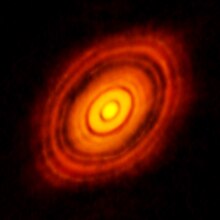
HL Tauri protoplanetary disk.

By the summer of 2011, sufficient telescopes were operational during the extensive program of testing prior to the Early Science phase for the first images to be captured. These early images gave a first glimpse of the potential of the new array that will produce much better quality images in the future as the scale of the array continues to increase.

The target of the observation was a pair of colliding galaxies with dramatically distorted shapes, known as the Antennae Galaxies. Although ALMA did not observe the entire galaxy merger, the result is the best submillimeter-wavelength image ever made of the Antennae Galaxies, showing the clouds of dense cold gas from which new stars form, which cannot be seen using visible light.

Comet studies

On 11 August 2014, astronomers released studies, using the Atacama Large Millimeter/submillimeter Array (ALMA) for the first time, that detailed the distribution of HCN, HNC, H2CO, and dust inside the comae of comets C/2012 F6 (Lemmon) and C/2012 S1 (ISON).

Planetary formation

An image of the protoplanetary disc surrounding HL Tauri (a very young T Tauri star in the constellation Taurus) was made public in 2014, showing a series of concentric bright rings separated by gaps, indicating protoplanet formation. As of 2014, most theories did not expect planetary formation in such a young (100,000-1,000,000-year-old) system, so the new data spurred renewed theories of protoplanetary development. One theory suggests that the faster accretion rate might be due to the complex magnetic field of the protoplanetary disc.

Event Horizon Telescope

ALMA participated in the Event Horizon Telescope project, which produced the first direct image of a black hole, published in 2019.

Phosphine in the atmosphere of Venus

ALMA participated in the claimed detection of phosphine, a biomarker, in the air of Venus. As no known non-biological source of phosphine on Venus could produce phosphine in the concentrations detected, this would have indicated the presence of biological organisms in the atmosphere of Venus. Later reanalyses cast doubt on the detection, although later analyses confirmed the results. The detection remains controversial, and is awaiting additional measurements.

Global collaboration

Several ALMA dishes

The Atacama Large Millimeter/submillimeter Array (ALMA), an international astronomy facility, is a partnership of Europe, North America and East Asia in cooperation with the Republic of Chile. ALMA is funded in Europe by the European Southern Observatory (ESO), in North America by the U.S. National Science Foundation (NSF) in cooperation with the National Research Council of Canada (NRC) and the National Science Council of Taiwan (NSC) and in East Asia by the National Institutes of Natural Sciences of Japan (NINS) in cooperation with the Academia Sinica (AS) in Taiwan. ALMA construction and operations are led on behalf of Europe by ESO, on behalf of North America by the National Radio Astronomy Observatory (NRAO), which is managed by Associated Universities, Inc (AUI) and on behalf of East Asia by the National Astronomical Observatory of Japan (NAOJ). The Joint ALMA Observatory (JAO) provides the unified leadership and management of the construction, commissioning and operation of ALMA. Its current director since February 2018 is Sean Dougherty.

ALMA regional centre (ARC)

The ALMA regional centre (ARC) has been designed as an interface between user communities of the major contributors of the ALMA project and the JAO. Activates for operating the ARC have also divided into the three main regions involved (Europe, North America and East Asia). The European ARC (led by ESO) has been further subdivided into ARC-nodes located across Europe in Bonn-Bochum-Cologne, Bologna, Ondřejov, Onsala, IRAM (Grenoble), Leiden and JBCA (Manchester).

The core purpose of the ARC is to assist the user community with the preparation of observing proposals, ensure observing programs meet their scientific goals efficiently, run a help-desk for submitting proposals and observing programs, delivering the data to principal investigators, maintenance of the ALMA data archive, assistance with the calibration of data and providing user feedback.

Project detail

ALMA site from above

Atacama Compact Array

The Atacama Compact Array

The Atacama Compact Array, ACA, is a subset of 16 closely separated antennae that will greatly improve ALMA's ability to study celestial objects with a large angular size, such as molecular clouds and nearby galaxies. The antennae forming the Atacama Compact Array, four 12-meter antennae and twelve 7-meter antennae, were produced and delivered by Japan. In 2013, the Atacama Compact Array was named the Morita Array after Professor Koh-ichiro Morita, a member of the Japanese ALMA team and designer of the ACA, who died on 7 May 2012 in Santiago.

Work stoppage

In August 2013, workers at the telescope went on strike to demand better pay and working conditions. This is one of the first strikes to affect an astronomical observatory. The work stoppage began after the observatory failed to reach an agreement with the workers' union. After 17 days an agreement was reached providing for reduced schedules and higher pay for work done at high altitude.

In March 2020, ALMA was shut down due to the COVID-19 pandemic. It also delayed the cycle 8 proposal submission deadline and suspended public visits to the site.

On October 29, 2022, ALMA suspended observations due to a cyber attack. Observations were restarted 48 days later, on December 16, 2022.

Declaration of the Rights of Man and of the Citizen

From Wikipedia, the free encyclopedia https://en.wikipedia.org/wiki/Declarati...