Search This Blog

Saturday, June 6, 2020

Mechanical advantage

From Wikipedia, the free encyclopedia
 
Mechanical advantage is a measure of the force amplification achieved by using a tool, mechanical device or machine system. The device preserves the input power and simply trades off forces against movement to obtain a desired amplification in the output force. The model for this is the law of the lever. Machine components designed to manage forces and movement in this way are called mechanisms. An ideal mechanism transmits power without adding to or subtracting from it. This means the ideal mechanism does not include a power source, is frictionless, and is constructed from rigid bodies that do not deflect or wear. The performance of a real system relative to this ideal is expressed in terms of efficiency factors that take into account departures from the ideal.

Lever

The lever is a movable bar that pivots on a fulcrum attached to or positioned on or across a fixed point. The lever operates by applying forces at different distances from the fulcrum, or pivot. The location of the fulcrum determines a lever's class. Where a lever rotates, continuously, it functions as a rotary 2nd-class lever. The motion of the lever's end-point describes a fixed orbit, where mechanical energy can be exchanged. (see a hand-crank as an example.)

In modern times, this kind of rotary leverage is widely used; see a (rotary) 2nd-class lever; see gears, pulleys or friction drive, used in a mechanical power transmission scheme. It is common for mechanical advantage to be manipulated in a 'collapsed' form, via the use of more than one gear (a gearset). In such a gearset, gears having smaller radii and less inherent mechanical advantage are used. In order to make use of non-collapsed mechanical advantage, it is necessary to use a 'true length' rotary lever. See, also, the incorporation of mechanical advantage into the design of certain types of electric motors; one design is an 'outrunner'. 

Lever mechanical advantage.png
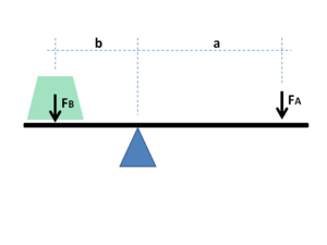
As the lever pivots on the fulcrum, points farther from this pivot move faster than points closer to the pivot. The power into and out of the lever is the same, so must come out the same when calculations are being done. Power is the product of force and velocity, so forces applied to points farther from the pivot must be less than when applied to points closer in.

If a and b are distances from the fulcrum to points A and B and if force FA applied to A is the input force and FB exerted at B is the output, the ratio of the velocities of points A and B is given by a/b so the ratio of the output force to the input force, or mechanical advantage, is given by
This is the law of the lever, which was proven by Archimedes using geometric reasoning. It shows that if the distance a from the fulcrum to where the input force is applied (point A) is greater than the distance b from fulcrum to where the output force is applied (point B), then the lever amplifies the input force. If the distance from the fulcrum to the input force is less than from the fulcrum to the output force, then the lever reduces the input force. Recognizing the profound implications and practicalities of the law of the lever, Archimedes has been famously attributed the quotation "Give me a place to stand and with a lever I will move the whole world."

The use of velocity in the static analysis of a lever is an application of the principle of virtual work.

Speed ratio

The requirement for power input to an ideal mechanism to equal power output provides a simple way to compute mechanical advantage from the input-output speed ratio of the system.

The power input to a gear train with a torque TA applied to the drive pulley which rotates at an angular velocity of ωA is P=TAωA.

Because the power flow is constant, the torque TB and angular velocity ωB of the output gear must satisfy the relation
which yields
This shows that for an ideal mechanism the input-output speed ratio equals the mechanical advantage of the system. This applies to all mechanical systems ranging from robots to linkages.

Gear trains

Gear teeth are designed so that the number of teeth on a gear is proportional to the radius of its pitch circle, and so that the pitch circles of meshing gears roll on each other without slipping. The speed ratio for a pair of meshing gears can be computed from ratio of the radii of the pitch circles and the ratio of the number of teeth on each gear, its gear ratio

Animation: Small gear (left) and large gear (right) with a black background
Two meshing gears transmit rotational motion.
 
The velocity v of the point of contact on the pitch circles is the same on both gears, and is given by
where input gear A has radius rA and meshes with output gear B of radius rB, therefore,
where NA is the number of teeth on the input gear and NB is the number of teeth on the output gear.
The mechanical advantage of a pair of meshing gears for which the input gear has NA teeth and the output gear has NB teeth is given by
This shows that if the output gear GB has more teeth than the input gear GA, then the gear train amplifies the input torque. And, if the output gear has fewer teeth than the input gear, then the gear train reduces the input torque. 

If the output gear of a gear train rotates more slowly than the input gear, then the gear train is called a speed reducer (Force multiplier). In this case, because the output gear must have more teeth than the input gear, the speed reducer will amplify the input torque.

Chain and belt drives

Mechanisms consisting of two sprockets connected by a chain, or two pulleys connected by a belt are designed to provide a specific mechanical advantage in power transmission systems.

The velocity v of the chain or belt is the same when in contact with the two sprockets or pulleys:
where the input sprocket or pulley A meshes with the chain or belt along the pitch radius rA and the output sprocket or pulley B meshes with this chain or belt along the pitch radius rB,
therefore
where NA is the number of teeth on the input sprocket and NB is the number of teeth on the output sprocket. For a toothed belt drive, the number of teeth on the sprocket can be used. For friction belt drives the pitch radius of the input and output pulleys must be used.

The mechanical advantage of a pair of a chain drive or toothed belt drive with an input sprocket with NA teeth and the output sprocket has NB teeth is given by
The mechanical advantage for friction belt drives is given by
Chains and belts dissipate power through friction, stretch and wear, which means the power output is actually less than the power input, which means the mechanical advantage of the real system will be less than that calculated for an ideal mechanism. A chain or belt drive can lose as much as 5% of the power through the system in friction heat, deformation and wear, in which case the efficiency of the drive is 95%.

Example: bicycle chain drive

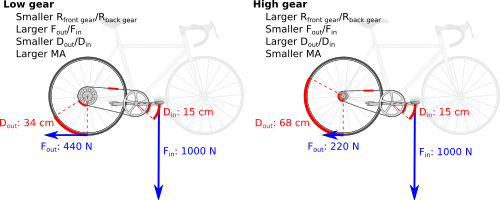
Mechanical advantage in different gears of a bicycle. Typical forces applied to the bicycle pedal and to the ground are shown, as are corresponding distances moved by the pedal and rotated by the wheel. Note that even in low gear the MA of a bicycle is less than 1.
 
Consider the 18-speed bicycle with 7 in (radius) cranks and 26 in (diameter) wheels. If the sprockets at the crank and at the rear drive wheel are the same size, then the ratio of the output force on the tire to the input force on the pedal can be calculated from the law of the lever to be
Now, assume that the front sprockets have a choice of 28 and 52 teeth, and that the rear sprockets have a choice of 16 and 32 teeth. Using different combinations, we can compute the following speed ratios between the front and rear sprockets 

Speed ratios and total MA

input (small) input (large) output (small) output (large) speed ratio crank-wheel ratio total MA
low speed 28 - - 32 1.14 0.54 0.62
mid 1 - 52 - 32 0.62 0.54 0.33
mid 2 28 - 16 - 0.57 0.54 0.31
high speed - 52 16 - 0.30 0.54 0.16

The ratio of the force driving the bicycle to the force on the pedal, which is the total mechanical advantage of the bicycle, is the product of the speed ratio (or teeth ratio of output sproket/input sproket) and the crank-wheel lever ratio.

Notice that in every case the force on the pedals is greater than the force driving the bicycle forward (in the illustration above, the corresponding backward-directed reaction force on the ground is indicated). This low mechanical advantage keeps the pedal crank speed low relative to the speed of the drive wheel, even in low gears.

Block and tackle

A block and tackle is an assembly of a rope and pulleys that is used to lift loads. A number of pulleys are assembled together to form the blocks, one that is fixed and one that moves with the load. The rope is threaded through the pulleys to provide mechanical advantage that amplifies that force applied to the rope.

In order to determine the mechanical advantage of a block and tackle system consider the simple case of a gun tackle, which has a single mounted, or fixed, pulley and a single movable pulley. The rope is threaded around the fixed block and falls down to the moving block where it is threaded around the pulley and brought back up to be knotted to the fixed block.

The mechanical advantage of a block and tackle equals the number of sections of rope that support the moving block; shown here it is 2, 3, 4, 5, and 6, respectively.
 
Let S be the distance from the axle of the fixed block to the end of the rope, which is A where the input force is applied. Let R be the distance from the axle of the fixed block to the axle of the moving block, which is B where the load is applied.


The total length of the rope L can be written as

where K is the constant length of rope that passes over the pulleys and does not change as the block and tackle moves.

The velocities VA and VB of the points A and B are related by the constant length of the rope, that is
or
The negative sign shows that the velocity of the load is opposite to the velocity of the applied force, which means as we pull down on the rope the load moves up.

Let VA be positive downwards and VB be positive upwards, so this relationship can be written as the speed ratio
where 2 is the number of rope sections supporting the moving block.

Let FA be the input force applied at A the end of the rope, and let FB be the force at B on the moving block. Like the velocities FA is directed downwards and FB is directed upwards.

For an ideal block and tackle system there is no friction in the pulleys and no deflection or wear in the rope, which means the power input by the applied force FAVA must equal the power out acting on the load FBVB, that is
The ratio of the output force to the input force is the mechanical advantage of an ideal gun tackle system,
This analysis generalizes to an ideal block and tackle with a moving block supported by n rope sections,
This shows that the force exerted by an ideal block and tackle is n times the input force, where n is the number of sections of rope that support the moving block.

Efficiency

Mechanical advantage that is computed using the assumption that no power is lost through deflection, friction and wear of a machine is the maximum performance that can be achieved. For this reason, it is often called the ideal mechanical advantage (IMA). In operation, deflection, friction and wear will reduce the mechanical advantage. The amount of this reduction from the ideal to the actual mechanical advantage (AMA) is defined by a factor called efficiency, a quantity which is determined by experimentation.

As an example, using a block and tackle with six rope sections and a 600 lb load, the operator of an ideal system would be required to pull the rope six feet and exert 100 lbF of force to lift the load one foot. Both the ratios Fout / Fin and Vin / Vout show that the IMA is six. For the first ratio, 100 lbF of force input results in 600 lbF of force out. In an actual system, the force out would be less than 600 pounds due to friction in the pulleys. The second ratio also yields a MA of 6 in the ideal case but a smaller value in the practical scenario; it does not properly account for energy losses such as rope stretch. Subtracting those losses from the IMA or using the first ratio yields the AMA.

Ideal mechanical advantage

The ideal mechanical advantage (IMA), or theoretical mechanical advantage, is the mechanical advantage of a device with the assumption that its components do not flex, there is no friction, and there is no wear. It is calculated using the physical dimensions of the device and defines the maximum performance the device can achieve.

The assumptions of an ideal machine are equivalent to the requirement that the machine does not store or dissipate energy; the power into the machine thus equals the power out. Therefore, the power P is constant through the machine and force times velocity into the machine equals the force times velocity out—that is,
The ideal mechanical advantage is the ratio of the force out of the machine (load) to the force into the machine (effort), or
Applying the constant power relationship yields a formula for this ideal mechanical advantage in terms of the speed ratio:
The speed ratio of a machine can be calculated from its physical dimensions. The assumption of constant power thus allows use of the speed ratio to determine the maximum value for the mechanical advantage.

Actual mechanical advantage

The actual mechanical advantage (AMA) is the mechanical advantage determined by physical measurement of the input and output forces. Actual mechanical advantage takes into account energy loss due to deflection, friction, and wear.

The AMA of a machine is calculated as the ratio of the measured force output to the measured force input,
where the input and output forces are determined experimentally.

The ratio of the experimentally determined mechanical advantage to the ideal mechanical advantage is the mechanical efficiency η of the machine,
Wheel and axle

From Wikipedia, the free encyclopedia
 
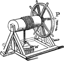
The windlass is a well-known application of the wheel and axle.

The wheel and axle is a machine consisting of a wheel attached to a smaller axle so that these two parts rotate together in which a force is transferred from one to the other. A hinge or bearing supports the axle, allowing rotation. It can amplify force; a small force applied to the periphery of the large wheel can move a larger load attached to the axle.

The wheel and axle can be viewed as a version of the lever, with a drive force applied tangentially to the perimeter of the wheel and a load force applied to the axle, respectively, that are balanced around the hinge which is the fulcrum. The mechanical advantage of the wheel and axle is the ratio of the distances from the fulcrum to the applied loads, or what is the same thing the ratio of the diameter of the wheel and axle. A major application is in wheeled vehicles, in which the wheel and axle are used to reduce friction of the moving vehicle with the ground. Other examples of devices which use the wheel and axle are capstans, belt drives and gears.

Capstan bars inserted into the capstan provide the mechanical advantage of a wheel and axle to lift an anchor
 
Turning a doorknob rotates the spindle which moves the latch.
 
Waterwheel driving a rope winch to lift loads in medieval mining
 
Ljubljana Marshes Wheel with axle is oldest wooden wheel yet discovered dating to Copper Age (approx. 5,150 BP)

History

The Halaf culture of 6500–5100 BCE has been credited with the earliest depiction of a wheeled vehicle, but this is doubtful as there is no evidence of Halafians using either wheeled vehicles or even pottery wheels.

One of the first applications of the wheel to appear was the potter's wheel, used by prehistoric cultures to fabricate clay pots. The earliest type, known as "tournettes" or "slow wheels", were known in the Middle East by the 5th millennium BCE. One of the earliest examples was discovered at Tepe Pardis, Iran, and dated to 5200–4700 BCE. These were made of stone or clay and secured to the ground with a peg in the center, but required significant effort to turn. True potter's wheels, which are freely-spinning and have a wheel and axle mechanism, were developed in Mesopotamia (Iraq) by 4200–4000 BCE. The oldest surviving example, which was found in Ur (modern day Iraq), dates to approximately 3100 BCE.

Evidence of wheeled vehicles appeared by the late 4th millennium BCE. Depictions of wheeled wagons found on clay tablet pictographs at the Eanna district of Uruk, in the Sumerian civilization of Mesopotamia, are dated between 3700–3500 BCE. In the second half of the 4th millennium BCE, evidence of wheeled vehicles appeared near-simultaneously in the Northern Caucasus (Maykop culture) and Eastern Europe (Cucuteni–Trypillian culture). Depictions of a wheeled vehicle appeared between 3500 and 3350 BCE in the Bronocice clay pot excavated in a Funnelbeaker culture settlement in southern Poland. In nearby Olszanica, a 2.2 m wide door was constructed (2.2 wide doors were constructed) for wagon entry; this barn was 40 m long and had 3 doors. Surviving evidence of a wheel–axle combination, from Stare Gmajne near Ljubljana in Slovenia (Ljubljana Marshes Wooden Wheel), is dated within two standard deviations to 3340–3030 BCE, the axle to 3360–3045 BCE. Two types of early Neolithic European wheel and axle are known; a circumalpine type of wagon construction (the wheel and axle rotate together, as in Ljubljana Marshes Wheel), and that of the Baden culture in Hungary (axle does not rotate). They both are dated to c. 3200–3000 BCE. Historians believe that there was a diffusion of the wheeled vehicle from the Near East to Europe around the mid-4th millennium BCE.

An early example of a wooden wheel and its axle was found in 2002 at the Ljubljana Marshes some 20 km south of Ljubljana, the capital of Slovenia. According to radiocarbon dating, it is between 5,100 and 5,350 years old. The wheel was made of ash and oak and had a radius of 70 cm and the axle was 120 cm long and made of oak.

In Roman Egypt, Hero of Alexandria identified the wheel and axle as one of the simple machines used to lift weights. This is thought to have been in the form of the windlass which consists of a crank or pulley connected to a cylindrical barrel that provides mechanical advantage to wind up a rope and lift a load such as a bucket from the well.

The wheel and axle was identified as one of six simple machines by Renaissance scientists, drawing from Greek texts on technology.

Mechanical advantage

The simple machine called a wheel and axle refers to the assembly formed by two disks, or cylinders, of different diameters mounted so they rotate together around the same axis.The thin rod which needs to be turned is called the axle and the wider object fixed to the axle, on which we apply force is called the wheel. A tangential force applied to the periphery of the large disk can exert a larger force on a load attached to the axle, achieving mechanical advantage. When used as the wheel of a wheeled vehicle the smaller cylinder is the axle of the wheel, but when used in a windlass, winch, and other similar applications (see medieval mining lift to right) the smaller cylinder may be separate from the axle mounted in the bearings. It cannot be used separately.

Assuming the wheel and axle does not dissipate or store energy, that is it has no friction or elasticity, the power input by the force applied to the wheel must equal the power output at the axle. As the wheel and axle system rotates around its bearings, points on the circumference, or edge, of the wheel move faster than points on the circumference, or edge, of the axle. Therefore, a force applied to the edge of the wheel must be less than the force applied to the edge of the axle, because power is the product of force and velocity.

Let a and b be the distances from the center of the bearing to the edges of the wheel A and the axle B. If the input force FA is applied to the edge of the wheel A and the force FB at the edge of the axle B is the output, then the ratio of the velocities of points A and B is given by a/b, so the ratio of the output force to the input force, or mechanical advantage, is given by
The mechanical advantage of a simple machine like the wheel and axle is computed as the ratio of the resistance to the effort. The larger the ratio the greater the multiplication of force (torque) created or distance achieved. By varying the radii of the axle and/or wheel, any amount of mechanical advantage may be gained. In this manner, the size of the wheel may be increased to an inconvenient extent. In this case a system or combination of wheels (often toothed, that is, gears) are used. As a wheel and axle is a type of lever, a system of wheels and axles is like a compound lever.

Ideal mechanical advantage

The mechanical advantage of a wheel and axle with no friction is called the ideal mechanical advantage (IMA). It is calculated with the following formula:

Actual mechanical advantage

All actual wheels have friction, which dissipates some of the power as heat. The actual mechanical advantage (AMA) of a wheel and axle is calculated with the following formula:
where
is the efficiency of the wheel, the ratio of power output to power input

Tool

From Wikipedia, the free encyclopedia

Display of agricultural tools
 
A modern toolbox

A tool is an object used to extend the ability of an individual to modify features of the surrounding environment. Although many animals use simple tools, only human beings, whose use of stone tools dates back hundreds of millennia, have been observed using tools to make other tools. The set of tools required to perform different tasks that are part of the same activity is called gear or equipment.

While one may apply the term tool loosely to many things that are means to an end (e.g., a fork), strictly speaking an object is a tool only if, besides being constructed to be held, it is also made of a material that allows its user to apply to it various degrees of force. If repeated use wears part of the tool down (like a knife blade), it may be possible to restore it; if it wears the tool out or breaks it, the tool must be replaced. Thus tool falls under the taxonomic category implement, and is on the same taxonomic rank as instrument, utensil, device, or ware.

History

Prehistoric stone tools over 10,000 years old, found in Les Combarelles cave, France
 
Carpentry tools recovered from the wreck of a 16th-century sailing ship, the Mary Rose. From the top, a mallet, brace, plane, handle of a T-auger, handle of a gimlet, possible handle of a hammer, and rule.
 
Stone and metal knives
 

Anthropologists believe that the use of tools was an important step in the evolution of mankind. Because tools are used extensively by both humans and wild chimpanzees, it is widely assumed that the first routine use of tools took place prior to the divergence between the two species. These early tools, however, were likely made of perishable materials such as sticks, or consisted of unmodified stones that cannot be distinguished from other stones as tools.

Stone artifacts only date back to about 2.5 million years ago. However, a 2010 study suggests the hominin species Australopithecus afarensis ate meat by carving animal carcasses with stone implements. This finding pushes back the earliest known use of stone tools among hominins to about 3.4 million years ago.

Finds of actual tools date back at least 2.6 million years in Ethiopia. One of the earliest distinguishable stone tool forms is the hand axe.

Up until recently, weapons found in digs were the only tools of “early man” that were studied and given importance. Now, more tools are recognized as culturally and historically relevant. As well as hunting, other activities required tools such as preparing food, “...nutting, leatherworking, grain harvesting and woodworking...” Included in this group are “flake stone tools".

Tools are the most important items that the ancient humans used to climb to the top of the food chain; by inventing tools, they were able to accomplish tasks that human bodies could not, such as using a spear or bow and arrow to kill prey, since their teeth were not sharp enough to pierce many animals' skins. “Man the hunter” as the catalyst for Hominin change has been questioned. Based on marks on the bones at archaeological sites, it is now more evident that pre-humans were scavenging off of other predators' carcasses rather than killing their own food.

Mechanical devices experienced a major expansion in their use in Ancient Greece and Ancient Rome with the systematic employment of new energy sources, especially waterwheels. Their use expanded through the Dark Ages with the addition of windmills.

Machine tools occasioned a surge in producing new tools in the industrial revolution. Advocates of nanotechnology expect a similar surge as tools become microscopic in size.

Functions

One can classify tools according to their basic functions:
Some tools may be combinations of other tools. An alarm-clock is for example a combination of a measuring tool (the clock) and a perception tool (the alarm). This enables the alarm-clock to be a tool that falls outside of all the categories mentioned above.

There is some debate on whether to consider protective gear items as tools, because they do not directly help perform work, just protect the worker like ordinary clothing. They do meet the general definition of tools and in many cases are necessary for the completion of the work. Personal protective equipment includes such items as gloves, safety glasses, ear defenders and biohazard suits.

Simple machines

A simple machine is a mechanical device that changes the direction or magnitude of a force. In general, they are the simplest mechanisms that use mechanical advantage (also called leverage) to multiply force. The six classical simple machines which were defined by Renaissance scientists are:

Tool substitution

Often, by design or coincidence, a tool may share key functional attributes with one or more other tools. In this case, some tools can substitute for other tools, either as a makeshift solution or as a matter of practical efficiency. "One tool does it all" is a motto of some importance for workers who cannot practically carry every specialized tool to the location of every work task; such as a carpenter who does not necessarily work in a shop all day and needs to do jobs in a customer's house. Tool substitution may be divided broadly into two classes: substitution "by-design", or "multi-purpose", and substitution as makeshift. Substitution "by-design" would be tools that are designed specifically to accomplish multiple tasks using only that one tool.

Substitution as makeshift is when human ingenuity comes into play and a tool is used for its unintended purpose such as a mechanic using a long screw driver to separate a cars control arm from a ball joint instead of using a tuning fork. In many cases, the designed secondary functions of tools are not widely known. As an example of the former, many wood-cutting hand saws integrate a carpenter's square by incorporating a specially shaped handle that allows 90° and 45° angles to be marked by aligning the appropriate part of the handle with an edge and scribing along the back edge of the saw. The latter is illustrated by the saying "All tools can be used as hammers." Nearly all tools can be used to function as a hammer, even though very few tools are intentionally designed for it and even fewer work as well as the original.

Tools are also often used to substitute for many mechanical apparatuses, especially in older mechanical devices. In many cases a cheap tool could be used to occupy the place of a missing mechanical part. A window roller in a car could easily be replaced with a pair of vise-grips or regular pliers. A transmission shifter or ignition switch would be able to be replaced with a screw-driver. Again, these would be considered tools that are being used for their unintended purposes, substitution as makeshift. Tools such as a rotary tool would be considered the substitution "by-design", or "multi-purpose". This class of tools allows the use of one tool that has at least two different capabilities. "Multi-purpose" tools are basically multiple tools in one device/tool. Tools such as this are often power tools that come with many different attachments like a rotary tool does, so you could say that a power drill is a "multi-purpose" tool because you can do more than just one thing with a power drill.

Multi-use tools

Bicycle multi-tool
 
A multi-tool is a hand tool that incorporates several tools into a single, portable device; the Swiss army knife represents one of the earliest examples. Other tools have a primary purpose but also incorporate other functionality – for example, lineman's pliers incorporate a gripper and cutter, and are often used as a hammer; and some hand saws incorporate a carpenter's square in the right-angle between the blade's dull edge and the saw's handle. This would also be the category of "multi-purpose" tools, since they are also multiple tools in one (multi-use and multi-purpose can be used interchangeably – compare hand axe). These types of tools were specifically made to catch the eye of many different craftsman who traveled to do their work. To these workers these types of tools were revolutionary because they were one tool or one device that could do several different things. With this new revolution of tools the traveling craftsman would not have to carry so many tools with them to job sites, in that their space would be limited to the vehicle or to the beast of burden they were driving. Multi-use tools solve the problem of having to deal with many different tools.

Use by other animals

A Bonobo at the San Diego Zoo "fishing" for termites

Observation has confirmed that a number of species can use tools including monkeys, apes, elephants, several birds, and sea otters. Philosophers originally thought that only humans had the ability to make tools, until zoologists observed birds and apes making tools. Now the unique relationship of humans with tools is considered to be that we are the only species that uses tools to make other tools.

Recently, a Visayan warty pig was observed using a stick in digging a hole on the ground at a French zoo.

Tool metaphors

A telephone is a communication tool that interfaces between two people engaged in conversation at one level. It also interfaces between each user and the communication network at another level. It is in the domain of media and communications technology that a counter-intuitive aspect of our relationships with our tools first began to gain popular recognition. Marshall McLuhan famously said "We shape our tools. And then our tools shape us." McLuhan was referring to the fact that our social practices co-evolve with our use of new tools and the refinements we make to existing tools.

Representation of a Lie group

From Wikipedia, the free encyclopedia https://en.wikipedia.org/wiki/Representation_of_a_Lie_group...