Search This Blog

Monday, August 7, 2023

Complex geometry

From Wikipedia, the free encyclopedia
https://en.wikipedia.org/wiki/Complex_geometry

In mathematics, complex geometry is the study of geometric structures and constructions arising out of, or described by, the complex numbers. In particular, complex geometry is concerned with the study of spaces such as complex manifolds and complex algebraic varieties, functions of several complex variables, and holomorphic constructions such as holomorphic vector bundles and coherent sheaves. Application of transcendental methods to algebraic geometry falls in this category, together with more geometric aspects of complex analysis.

Complex geometry sits at the intersection of algebraic geometry, differential geometry, and complex analysis, and uses tools from all three areas. Because of the blend of techniques and ideas from various areas, problems in complex geometry are often more tractable or concrete than in general. For example, the classification of complex manifolds and complex algebraic varieties through the minimal model program and the construction of moduli spaces sets the field apart from differential geometry, where the classification of possible smooth manifolds is a significantly harder problem. Additionally, the extra structure of complex geometry allows, especially in the compact setting, for global analytic results to be proven with great success, including Shing-Tung Yau's proof of the Calabi conjecture, the Hitchin–Kobayashi correspondence, the nonabelian Hodge correspondence, and existence results for Kähler–Einstein metrics and constant scalar curvature Kähler metrics. These results often feed back into complex algebraic geometry, and for example recently the classification of Fano manifolds using K-stability has benefited tremendously both from techniques in analysis and in pure birational geometry.

Complex geometry has significant applications to theoretical physics, where it is essential in understanding conformal field theory, string theory, and mirror symmetry. It is often a source of examples in other areas of mathematics, including in representation theory where generalized flag varieties may be studied using complex geometry leading to the Borel–Weil–Bott theorem, or in symplectic geometry, where Kähler manifolds are symplectic, in Riemannian geometry where complex manifolds provide examples of exotic metric structures such as Calabi–Yau manifolds and hyperkähler manifolds, and in gauge theory, where holomorphic vector bundles often admit solutions to important differential equations arising out of physics such as the Yang–Mills equations. Complex geometry additionally is impactful in pure algebraic geometry, where analytic results in the complex setting such as Hodge theory of Kähler manifolds inspire understanding of Hodge structures for varieties and schemes as well as p-adic Hodge theory, deformation theory for complex manifolds inspires understanding of the deformation theory of schemes, and results about the cohomology of complex manifolds inspired the formulation of the Weil conjectures and Grothendieck's standard conjectures. On the other hand, results and techniques from many of these fields often feed back into complex geometry, and for example developments in the mathematics of string theory and mirror symmetry have revealed much about the nature of Calabi–Yau manifolds, which string theorists predict should have the structure of Lagrangian fibrations through the SYZ conjecture, and the development of Gromov–Witten theory of symplectic manifolds has led to advances in enumerative geometry of complex varieties.

The Hodge conjecture, one of the millennium prize problems, is a problem in complex geometry.

Idea

A typical example of a complex space is the complex projective line. It may be viewed either as the sphere, a smooth manifold arising from differential geometry, or the Riemann sphere, an extension of the complex plane by adding a point at infinity.

Broadly, complex geometry is concerned with spaces and geometric objects which are modelled, in some sense, on the complex plane. Features of the complex plane and complex analysis of a single variable, such as an intrinsic notion of orientability (that is, being able to consistently rotate 90 degrees counterclockwise at every point in the complex plane), and the rigidity of holomorphic functions (that is, the existence of a single complex derivative implies complex differentiability to all orders) are seen to manifest in all forms of the study of complex geometry. As an example, every complex manifold is canonically orientable, and a form of Liouville's theorem holds on compact complex manifolds or projective complex algebraic varieties.

Complex geometry is different in flavour to what might be called real geometry, the study of spaces based around the geometric and analytical properties of the real number line. For example, whereas smooth manifolds admit partitions of unity, collections of smooth functions which can be identically equal to one on some open set, and identically zero elsewhere, complex manifolds admit no such collections of holomorphic functions. Indeed, this is the manifestation of the identity theorem, a typical result in complex analysis of a single variable. In some sense, the novelty of complex geometry may be traced back to this fundamental observation.

It is true that every complex manifold is in particular a real smooth manifold. This is because the complex plane is, after forgetting its complex structure, isomorphic to the real plane . However, complex geometry is not typically seen as a particular sub-field of differential geometry, the study of smooth manifolds. In particular, Serre's GAGA theorem says that every projective analytic variety is actually an algebraic variety, and the study of holomorphic data on an analytic variety is equivalent to the study of algebraic data.

This equivalence indicates that complex geometry is in some sense closer to algebraic geometry than to differential geometry. Another example of this which links back to the nature of the complex plane is that, in complex analysis of a single variable, singularities of meromorphic functions are readily describable. In contrast, the possible singular behaviour of a continuous real-valued function is much more difficult to characterise. As a result of this, one can readily study singular spaces in complex geometry, such as singular complex analytic varieties or singular complex algebraic varieties, whereas in differential geometry the study of singular spaces is often avoided.

In practice, complex geometry sits in the intersection of differential geometry, algebraic geometry, and analysis in several complex variables, and a complex geometer uses tools from all three fields to study complex spaces. Typical directions of interest in complex geometry involve classification of complex spaces, the study of holomorphic objects attached to them (such as holomorphic vector bundles and coherent sheaves), and the intimate relationships between complex geometric objects and other areas of mathematics and physics.

Definitions

Complex geometry is concerned with the study of complex manifolds, and complex algebraic and complex analytic varieties. In this section, these types of spaces are defined and the relationships between them presented.

A complex manifold is a topological space such that:

  • is Hausdorff and second countable.
  • is locally homeomorphic to an open subset of for some . That is, for every point , there is an open neighbourhood of and a homeomorphism to an open subset . Such open sets are called charts.
  • If and are any two overlapping charts which map onto open sets of respectively, then the transition function is a biholomorphism.

Notice that since every biholomorphism is a diffeomorphism, and is isomorphism as a real vector space to , every complex manifold of dimension is in particular a smooth manifold of dimension , which is always an even number.

In contrast to complex manifolds which are always smooth, complex geometry is also concerned with possibly singular spaces. An affine complex analytic variety is a subset such that about each point , there is an open neighbourhood of and a collection of finitely many holomorphic functions such that . By convention we also require the set to be irreducible. A point is singular if the Jacobian matrix of the vector of holomorphic functions does not have full rank at , and non-singular otherwise. A projective complex analytic variety is a subset of complex projective space that is, in the same way, locally given by the zeroes of a finite collection of holomorphic functions on open subsets of .

One may similarly define an affine complex algebraic variety to be a subset which is locally given as the zero set of finitely many polynomials in complex variables. To define a projective complex algebraic variety, one requires the subset to locally be given by the zero set of finitely many homogeneous polynomials.

In order to define a general complex algebraic or complex analytic variety, one requires the notion of a locally ringed space. A complex algebraic/analytic variety is a locally ringed space which is locally isomorphic as a locally ringed space to an affine complex algebraic/analytic variety. In the analytic case, one typically allows to have a topology that is locally equivalent to the subspace topology due to the identification with open subsets of , whereas in the algebraic case is often equipped with a Zariski topology. Again we also by convention require this locally ringed space to be irreducible.

Since the definition of a singular point is local, the definition given for an affine analytic/algebraic variety applies to the points of any complex analytic or algebraic variety. The set of points of a variety which are singular is called the singular locus, denoted , and the complement is the non-singular or smooth locus, denoted . We say a complex variety is smooth or non-singular if it's singular locus is empty. That is, if it is equal to its non-singular locus.

By the implicit function theorem for holomorphic functions, every complex manifold is in particular a non-singular complex analytic variety, but is not in general affine or projective. By Serre's GAGA theorem, every projective complex analytic variety is actually a projective complex algebraic variety. When a complex variety is non-singular, it is a complex manifold. More generally, the non-singular locus of any complex variety is a complex manifold.

Types of complex spaces

Kähler manifolds

Complex manifolds may be studied from the perspective of differential geometry, whereby they are equipped with extra geometric structures such as a Riemannian metric or symplectic form. In order for this extra structure to be relevant to complex geometry, one should ask for it to be compatible with the complex structure in a suitable sense. A Kähler manifold is a complex manifold with a Riemannian metric and symplectic structure compatible with the complex structure. Every complex submanifold of a Kähler manifold is Kähler, and so in particular every non-singular affine or projective complex variety is Kähler, after restricting the standard Hermitian metric on or the Fubini-Study metric on respectively.

Other important examples of Kähler manifolds include Riemann surfaces, K3 surfaces, and Calabi–Yau manifolds.

Stein manifolds

Serre's GAGA theorem asserts that projective complex analytic varieties are actually algebraic. Whilst this is not strictly true for affine varieties, there is a class of complex manifolds that act very much like affine complex algebraic varieties, called Stein manifolds. A manifold is Stein if it is holomorphically convex and holomorphically separable (see the article on Stein manifolds for the technical definitions). It can be shown however that this is equivalent to being a complex submanifold of for some . Another way in which Stein manifolds are similar to affine complex algebraic varieties is that Cartan's theorems A and B hold for Stein manifolds.

Examples of Stein manifolds include non-compact Riemann surfaces and non-singular affine complex algebraic varieties.

Hyper-Kähler manifolds

A special class of complex manifolds is hyper-Kähler manifolds, which are Riemannian manifolds admitting three distinct compatible integrable almost complex structures which satisfy the quaternionic relations . Thus, hyper-Kähler manifolds are Kähler manifolds in three different ways, and subsequently have a rich geometric structure.

Examples of hyper-Kähler manifolds include ALE spaces, K3 surfaces, Higgs bundle moduli spaces, quiver varieties, and many other moduli spaces arising out of gauge theory and representation theory.

Calabi–Yau manifolds

A real two-dimensional slice of a quintic Calabi–Yau threefold

As mentioned, a particular class of Kähler manifolds is given by Calabi–Yau manifolds. These are given by Kähler manifolds with trivial canonical bundle . Typically the definition of a Calabi–Yau manifold also requires to be compact. In this case Yau's proof of the Calabi conjecture implies that admits a Kähler metric with vanishing Ricci curvature, and this may be taken as an equivalent definition of Calabi–Yau.

Calabi–Yau manifolds have found use in string theory and mirror symmetry, where they are used to model the extra 6 dimensions of spacetime in 10-dimensional models of string theory. Examples of Calabi–Yau manifolds are given by elliptic curves, K3 surfaces, and complex Abelian varieties.

Complex Fano varieties

A complex Fano variety is a complex algebraic variety with ample anti-canonical line bundle (that is, is ample). Fano varieties are of considerable interest in complex algebraic geometry, and in particular birational geometry, where they often arise in the minimal model program. Fundamental examples of Fano varieties are given by projective space where , and smooth hypersurfaces of of degree less than .

Toric varieties

Moment polytope describing the first Hirzebruch surface.

Toric varieties are complex algebraic varieties of dimension containing an open dense subset biholomorphic to , equipped with an action of which extends the action on the open dense subset. A toric variety may be described combinatorially by its toric fan, and at least when it is non-singular, by a moment polytope. This is a polygon in with the property that any vertex may be put into the standard form of the vertex of the positive orthant by the action of . The toric variety can be obtained as a suitable space which fibres over the polytope.

Many constructions that are performed on toric varieties admit alternate descriptions in terms of the combinatorics and geometry of the moment polytope or its associated toric fan. This makes toric varieties a particularly attractive test case for many constructions in complex geometry. Examples of toric varieties include complex projective spaces, and bundles over them.

Techniques in complex geometry

Due to the rigidity of holomorphic functions and complex manifolds, the techniques typically used to study complex manifolds and complex varieties differ from those used in regular differential geometry, and are closer to techniques used in algebraic geometry. For example, in differential geometry, many problems are approached by taking local constructions and patching them together globally using partitions of unity. Partitions of unity do not exist in complex geometry, and so the problem of when local data may be glued into global data is more subtle. Precisely when local data may be patched together is measured by sheaf cohomology, and sheaves and their cohomology groups are major tools.

For example, famous problems in the analysis of several complex variables preceding the introduction of modern definitions are the Cousin problems, asking precisely when local meromorphic data may be glued to obtain a global meromorphic function. These old problems can be simply solved after the introduction of sheaves and cohomology groups.

Special examples of sheaves used in complex geometry include holomorphic line bundles (and the divisors associated to them), holomorphic vector bundles, and coherent sheaves. Since sheaf cohomology measures obstructions in complex geometry, one technique that is used is to prove vanishing theorems. Examples of vanishing theorems in complex geometry include the Kodaira vanishing theorem for the cohomology of line bundles on compact Kähler manifolds, and Cartan's theorems A and B for the cohomology of coherent sheaves on affine complex varieties.

Complex geometry also makes use of techniques arising out of differential geometry and analysis. For example, the Hirzebruch-Riemann-Roch theorem, a special case of the Atiyah-Singer index theorem, computes the holomorphic Euler characteristic of a holomorphic vector bundle in terms of characteristic classes of the underlying smooth complex vector bundle.

Classification in complex geometry

One major theme in complex geometry is classification. Due to the rigid nature of complex manifolds and varieties, the problem of classifying these spaces is often tractable. Classification in complex and algebraic geometry often occurs through the study of moduli spaces, which themselves are complex manifolds or varieties whose points classify other geometric objects arising in complex geometry.

Riemann surfaces

The term moduli was coined by Bernhard Riemann during his original work on Riemann surfaces. The classification theory is most well-known for compact Riemann surfaces. By the classification of closed oriented surfaces, compact Riemann surfaces come in a countable number of discrete types, measured by their genus , which is a non-negative integer counting the number of holes in the given compact Riemann surface.

The classification essentially follows from the uniformization theorem, and is as follows:

  • g = 0:
  • g = 1: There is a one-dimensional complex manifold classifying possible compact Riemann surfaces of genus 1, so-called elliptic curves, the modular curve. By the uniformization theorem any elliptic curve may be written as a quotient where is a complex number with strictly positive imaginary part. The moduli space is given by the quotient of the group acting on the upper half plane by Möbius transformations.
  • g > 1: For each genus greater than one, there is a moduli space of genus g compact Riemann surfaces, of dimension . Similar to the case of elliptic curves, this space may be obtained by a suitable quotient of Siegel upper half-space by the action of the group

Holomorphic line bundles

Complex geometry is concerned not only with complex spaces, but other holomorphic objects attached to them. The classification of holomorphic line bundles on a complex variety is given by the Picard variety of .

The picard variety can be easily described in the case where is a compact Riemann surface of genus g. Namely, in this case the Picard variety is a disjoint union of complex Abelian varieties, each of which is isomorphic to the Jacobian variety of the curve, classifying divisors of degree zero up to linear equivalence. In differential-geometric terms, these Abelian varieties are complex tori, complex manifolds diffeomorphic to , possibly with one of many different complex structures.

By the Torelli theorem, a compact Riemann surface is determined by its Jacobian variety, and this demonstrates one reason why the study of structures on complex spaces can be useful, in that it can allow one to solve classify the spaces themselves.

Soviet space program

From Wikipedia, the free encyclopedia
 
USSR space program
Formed1955–1991
DissolvedDecember 25, 1991
Manager
Key peopleDesign Bureaus
Primary spaceportCosmodrome
Baikonur, Plesetsk
First flightSputnik 1
(4 October 1957)
First crewed flightVostok 1
(12 April 1961)
Last flight25 December 1991
Last crewed flightSoyuz TM-13
(2 October 1991)
SuccessesSee accomplishments
FailuresSee failures below
Partial failuresSee partial or cancelled projects
Soviet lunar program
Soviet cosmonaut Yuri Gagarin in Sweden—the first man in outer space.

The Soviet space program (Russian: Космическая программа СССР, romanizedKosmicheskaya programma SSSR) was the national space program of the former Union of Soviet Socialist Republics (USSR), active from 1955 until the dissolution of the Soviet Union in 1991.

Soviet investigations in rocketry began with the formation of a research laboratory in 1921, but these efforts were hampered by the devastating war with Germany. Competing in the Space Race with the United States and later with the European Union and China, the Soviet program was notable in setting many records in space exploration, including the first intercontinental missile (R-7 Semyorka) that launched the first satellite (Sputnik 1) and sent the first animal (Laika) into Earth orbit in 1957, and placed the first human in space in 1961, Yuri Gagarin. In addition, the Soviet program also saw the first woman in space, Valentina Tereshkova, in 1963 and the first spacewalk in 1965. Other milestones included computerized robotic missions exploring the Moon starting in 1959: being the first to reach the surface of the Moon, recording the first image of the far side of the Moon, and achieving the first soft landing on the Moon. The Soviet program also achieved the first space rover deployment with the Lunokhod programme in 1966, and sent the first robotic probe that automatically extracted a sample of lunar soil and brought it to Earth in 1970, Luna 16. The Soviet program was also responsible for leading the first interplanetary probes to Venus and Mars and made successful soft landings on these planets in the 1960s and 1970s. It put the first space station, Salyut 1, into low Earth orbit in 1971, and the first modular space station, Mir, in 1986. Its Interkosmos program was also notable for sending the first citizen of a country other than the United States or Soviet Union into space.

After WWII, the Soviet and US space programs both utilised German technology in their early efforts. Eventually, the program was managed under Sergei Korolev, who led the program based on unique ideas derived by Konstantin Tsiolkovsky, sometimes known as the father of theoretical astronautics. Contrary to its American, European, and Chinese competitors, who had their programs run under a single coordinating agency, the Soviet space program was divided and split among several internally competing design bureaus led by Korolev, Kerimov, Keldysh, Yangel, Glushko, Chelomey, Makeyev, Chertok and Reshetnev.

The Soviet space program served as an important marker of Soviet claims to its global superpower status.

Origins

Early Russian-Soviet efforts

Members of the Group for the Study of Reactive Motion (GIRD). 1931. Left to right: standing I.P. Fortikov, Yu A Pobedonostsev, Zabotin; sitting: A. Levitsky, Nadezhda Sumarokova, Sergei Korolev, Boris Cheranovsky, Friedrich Zander

The theory of space exploration had a solid basis in the Russian Empire before the First World War with the writings of the Russian and Soviet rocket scientist Konstantin Tsiolkovsky (1857–1935), who published pioneering papers in the late 19th and early 20th centuries on astronautic theory, including calculating the Rocket equation and in 1929 introduced the concept of the multistaged rocket. Additional astronautic and spaceflight theory was also provided by the Ukrainian and Soviet engineer and mathematician Yuri Kondratyuk who developed the first known lunar orbit rendezvous (LOR), a key concept for landing and return spaceflight from Earth to the Moon. The LOR was later used for the plotting of the first actual human spaceflight to the Moon. Many other aspects of spaceflight and space exploration are covered in his works. Both theoretical and practical aspects of spaceflight was also provided by the Latvian pioneer of rocketry and spaceflight Friedrich Zander, including suggesting in a 1925 paper that a spacecraft traveling between two planets could be accelerated at the beginning of its trajectory and decelerated at the end of its trajectory by using the gravity of the two planets' moons — a method known as gravity assist.

Gas Dynamics Laboratory (GDL)

The first Soviet development of rockets was in 1921 when the Soviet military sanctioned the commencement of a small research laboratory to explore solid fuel rockets, led by Nikolai Tikhomirov, a chemical engineer and supported by Vladimir Artemyev a Soviet engineer. Tikhomirov had commenced studying solid and Liquid-fueled rockets in 1894, and in 1915 he lodged a patent for "self-propelled aerial and water-surface mines." In 1928 the laboratory was renamed the Gas Dynamics Laboratory (GDL). The First test-firing of a solid fuel rocket was carried out in March 1928, which flew for about 1,300 meters Further developments in the early 1930s were led by Georgy Langemak. and 1932 in-air test firings of RS-82 missiles from an Tupolev I-4 aircraft armed with six launchers successfully took place.

Sergey Korolev

A key contributor to early soviet efforts came from a young Russian aircraft engineer Sergey Korolev, who would later become the de facto head of the Soviet space programme. In 1926 as an advanced student Korolev was mentored by the famous Soviet aircraft designer Andrey Tupolev, who was a professor at his University. In 1930 while working as a lead engineer on the Tupolev TB-3 heavy bomber he became interested in the possibilities of liquid-fueled rocket engines to propel airplanes. This led to contact with Zander, and sparked his interest in space exploration and rocketry.

Group for the Study of Reactive Motion (GIRD)

Rocket 09 (left) and 10 (GIRD-09 and GIRD-X). Museum of Cosmonautics and Rocket Technology; St. Petersburg.

Practical aspects built on early experiments carried out by members of the 'Group for the Study of Reactive Motion' (better known by its Russian acronym "GIRD") in the 1930s, where Zander, Korolev and other pioneers such as the Russian engineers Mikhail Tikhonravov, Leonid Dushkin, Vladimir Vetchinkin and Yuriy Pobedonostsev worked together. On August 18, 1933, the Leningrad branch of GIRD, led by Tikhonravov, launched the first hybrid propellant rocket, the GIRD-09, and on November 25, 1933, the Soviet's first liquid-fueled rocket GIRD-X.

Reactive Scientific Research Institute (RNII)

In 1933 GIRD was merged with GDL by the Soviet government to form the Reactive Scientific Research Institute (RNII), which brought together the best of the Soviet rocket talent, including Korolev, Langemak, Ivan Kleymyonov and former GDL engine designer Valentin Glushko. Early success of RNII included the conception in 1936 and first flight in 1941 of the RP-318 the Soviets first rocket-powered aircraft and the RS-82 and RS-132 missiles entered service by 1937, which became the basis for development in 1938 and serial production from 1940 to 1941 of the Katyusha multiple rocket launcher, another advance in the reactive propulsion field. RNII's research and development were very important for later achievements of the Soviet rocket and space programs.

During the 1930s Soviet rocket technology was comparable to Germany's, but Joseph Stalin's Great Purge severely damaged its progress. In November 1937, Kleymyonov and Langemak were arrested and later executed, Glushko and many other leading engineers were imprisoned in the Gulag. Korolev was arrested in June 1938 and sent to a forced labour camp in Kolyma in June 1939. However, due to intervention by Tupolev, he was relocated to a prison for scientists and engineers in September 1940.

World War II

During World War II rocketry efforts were carried out by three Soviet design bureaus. RNII continued to develop and improve solid fuel rockets, including the RS-82 and RS-132 missiles and the Katyusha rocket launcher, where Pobedonostsev and Tikhonravov continued to work on rocket design. In 1944 RNII was renamed Scientific Research Institute No 1 (NII-I) and combined with design bureau OKB-293, led by Soviet engineer Viktor Bolkhovitinov, which developed, with Aleksei Isaev, Boris Chertok, Leonid Voskresensky and Nikolay Pilyugin a short-range rocket powered interceptor called Bereznyak-Isayev BI-1.

Special Design Bureau for Special Engines (OKB-SD) was led by Glushko and focused on developing auxiliary liquid-fueled rocket engines to assist takeoff and climbing of prop aircraft, including the RD-IKhZ, RD-2 and RD-3. In 1944, the RD-1 kHz auxiliary rocket motor was tested in a fast-climb Lavochkin La-7R for protection of the capital from high-altitude Luftwaffe attacks. In 1942 Korolev was transferred to OKB-SD, where he proposed development of the long rang missiles D-1 and D-2.

The third design bureau was Plant No 51 (OKB-51), led by Soviet Ukrainian Engineer Vladimir Chelomey, where he created the first Soviet pulsating air jet engine in 1942, independently of similar contemporary developments in Nazi Germany.

German influence

During World War II Nazi Germany developed rocket technology that was more advanced than the Allies and a race commenced between the Soviet Union and the United States to capture and exploit the technology. Soviet rocket specialist were sent to Germany in 1945 to obtain V-2 rockets and worked with German specialists in Germany and later in the Soviet Union to understand and replicate the rocket technology. The involvement of German scientists and engineers was an essential catalyst to early Soviet efforts. In 1945 and 1946 the use of German expertise was invaluable in reducing the time needed to master the intricacies of the V-2 rocket, establishing production of the R-1 rocket and enable a base for further developments. However, after 1947 the Soviets made very little use of German specialists and their influence on the future Soviet rocket program was marginal.

Sputnik and Vostok

Chief Designer Sergei Korolev (left), with the father of the Soviet atomic bomb Igor Kurchatov, and Chief Theoretician Mstislav Keldysh in 1956

The Soviet space program was tied to the USSR's Five-Year Plans and from the start was reliant on support from the Soviet military. Although he was "single-mindedly driven by the dream of space travel", Korolev generally kept this a secret while working on military projects—especially, after the Soviet Union's first atomic bomb test in 1949, a missile capable of carrying a nuclear warhead to the United States—as many mocked the idea of launching satellites and crewed spacecraft. Nonetheless, the first Soviet rocket with animals aboard launched in July 1951; the two dogs were recovered alive after reaching 101 km in altitude. Two months ahead of America's first such achievement, this and subsequent flights gave the Soviets valuable experience with space medicine.

Because of its global range and large payload of approximately five tons, the reliable R-7 was not only effective as a strategic delivery system for nuclear warheads, but also as an excellent basis for a space vehicle. The United States' announcement in July 1955 of its plan to launch a satellite during the International Geophysical Year greatly benefited Korolev in persuading Soviet leader Nikita Khrushchev to support his plans. In a letter addressed to Khrushchev, Korolev stressed the necessity of launching a "simple satellite" in order to compete with the American space effort. Plans were approved for Earth-orbiting satellites (Sputnik) to gain knowledge of space, and four uncrewed military reconnaissance satellites, Zenit. Further planned developments called for a crewed Earth orbit flight by and an uncrewed lunar mission at an earlier date.

A replica of Sputnik 1

After the first Sputnik proved to be a successful propaganda coup, Korolev—now known publicly only as the anonymous "Chief Designer of Rocket-Space Systems"—was charged to accelerate the crewed program, the design of which was combined with the Zenit program to produce the Vostok spacecraft. After Sputnik, Soviet scientists and program leaders envisioned establishing a crewed station to study the effects of zero-gravity and the long term effects on lifeforms in a space environment. Still influenced by Tsiolkovsky—who had chosen Mars as the most important goal for space travel—in the early 1960s the Soviet program under Korolev created substantial plans for crewed trips to Mars as early as 1968 to 1970. With closed-loop life support systems and electrical rocket engines, and launched from large orbiting space stations, these plans were much more ambitious than America's goal of landing on the Moon.

Funding and support

The Vostok rocket at the VDNH

The Soviet space program was secondary in military funding to the Strategic Rocket Forces' ICBMs. While the West believed that Khrushchev personally ordered each new space mission for propaganda purposes, and the Soviet leader did have an unusually close relationship with Korolev and other chief designers, Khrushchev emphasized missiles rather than space exploration and was not very interested in competing with Apollo.

While the government and the Communist Party used the program's successes as propaganda tools after they occurred, systematic plans for missions based on political reasons were rare, one exception being Valentina Tereshkova, the first woman in space, on Vostok 6 in 1963. Missions were planned based on rocket availability or ad hoc reasons, rather than scientific purposes. For example, the government in February 1962 abruptly ordered an ambitious mission involving two Vostoks simultaneously in orbit launched "in ten days time" to eclipse John Glenn's Mercury-Atlas 6 that month; the program could not do so until August, with Vostok 3 and Vostok 4.

Internal competition

Unlike the American space program, which had NASA as a single coordinating structure directed by its administrator, James Webb through most of the 1960s, the USSR's program was split between several competing design groups. Despite the remarkable successes of the Sputnik Program between 1957 and 1961 and Vostok Program between 1961 and 1964, after 1958 Korolev's OKB-1 design bureau faced increasing competition from his rival chief designers, Mikhail Yangel, Valentin Glushko, and Vladimir Chelomei. Korolev planned to move forward with the Soyuz craft and N-1 heavy booster that would be the basis of a permanent crewed space station and crewed exploration of the Moon. However, Dmitry Ustinov directed him to focus on near-Earth missions using the Voskhod spacecraft, a modified Vostok, as well as on uncrewed missions to nearby planets Venus and Mars.

Yangel had been Korolev's assistant but with the support of the military, he was given his own design bureau in 1954 to work primarily on the military space program. This had the stronger rocket engine design team including the use of hypergolic fuels but following the Nedelin catastrophe in 1960 Yangel was directed to concentrate on ICBM development. He also continued to develop his own heavy booster designs similar to Korolev's N-1 both for military applications and for cargo flights into space to build future space stations.

Glushko was the chief rocket engine designer but he had a personal friction with Korolev and refused to develop the large single chamber cryogenic engines that Korolev needed to build heavy boosters.

Chelomey benefited from the patronage of Khrushchev and in 1960 was given the plum job of developing a rocket to send a crewed vehicle around the Moon and a crewed military space station. With limited space experience, his development was slow.

The progress of the Apollo program alarmed the chief designers, who each advocated for his own program as the response. Multiple, overlapping designs received approval, and new proposals threatened already approved projects. Due to Korolev's "singular persistence", in August 1964—more than three years after the United States declared its intentions—the Soviet Union finally decided to compete for the moon. It set the goal of a lunar landing in 1967—the 50th anniversary of the October Revolution—or 1968. At one stage in the early 1960s the Soviet space program was actively developing multiple launchers and spacecraft. With the fall of Krushchev in 1964, Korolev was given complete control of the crewed program.

In 1961, Valentin Bondarenko, a cosmonaut and member of the Vostok Spacecraft, was killed in an endurance experiment after the chamber he was in caught on fire. The Soviet Union chose to cover up his death and continue on with the space program.

After Korolev

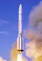
Launch of a Proton-K

Korolev died in January 1966, following a routine operation that uncovered colon cancer, from complications of heart disease and severe hemorrhaging. Kerim Kerimov, who had previously served as the head of the Strategic Rocket Forces and had participated in the State Commission for Vostok as part of his duties, was appointed Chairman of the State Commission on Piloted Flights and headed it for the next 25 years (1966–1991). He supervised every stage of development and operation of both crewed space complexes as well as uncrewed interplanetary stations for the former Soviet Union. One of Kerimov's greatest achievements was the launch of Mir in 1986.

The leadership of the OKB-1 design bureau was given to Vasily Mishin, who had the task of sending a human around the Moon in 1967 and landing a human on it in 1968. Mishin lacked Korolev's political authority and still faced competition from other chief designers. Under pressure, Mishin approved the launch of the Soyuz 1 flight in 1967, even though the craft had never been successfully tested on an uncrewed flight. The mission launched with known design problems and ended with the vehicle crashing to the ground, killing Vladimir Komarov. This was the first in-flight fatality of any space program.

Following this tragedy and under new pressures, Mishin developed a drinking problem. The Soviets were beaten in sending the first crewed flight around the Moon in 1968 by Apollo 8, but Mishin pressed ahead with development of the flawed super heavy N1, in the hope that the Americans would have a setback, leaving enough time to make the N1 workable and land a man on the Moon first. There was a success with the joint flight of Soyuz 4 and Soyuz 5 in January 1969 that tested the rendezvous, docking, and crew transfer techniques that would be used for the landing, and the LK lander was tested successfully in earth orbit. But after four uncrewed test launches of the N1 ended in failure, the program was suspended for two years and then cancelled, removing any chance of the Soviets landing men on the Moon before the United States.

The American and Soviet crews of the Apollo–Soyuz mission

Besides the crewed landings, the abandoned Soviet Moon program included the multipurpose moon base Zvezda, first detailed with developed mockups of expedition vehicles and surface modules.

Following this setback, Chelomey convinced Ustinov to approve a program in 1970 to advance his Almaz military space station as a means of beating the US's announced Skylab. Mishin remained in control of the project that became Salyut but the decision backed by Mishin to fly a three-man crew without pressure suits rather than a two-man crew with suits to Salyut 1 in 1971 proved fatal when the re-entry capsule depressurized killing the crew on their return to Earth. Mishin was removed from many projects, with Chelomey regaining control of Salyut. After working with NASA on the Apollo–Soyuz, the Soviet leadership decided a new management approach was needed, and in 1974 the N1 was canceled and Mishin was out of office. The design bureau was renamed NPO Energia with Glushko as chief designer.

In contrast with the difficulty faced in its early crewed lunar programs, the USSR found significant success with its remote moon operations, achieving two historical firsts with the automatic Lunokhod and the Luna sample return missions. The Mars probe program was also continued with some success, while the explorations of Venus and then of the Halley comet by the Venera and Vega probe programs were more effective.

In spite of many other Soviet-allied nations contributed to the national space program, the Soviet program was mostly inherited by the Russian Federation and fewer facilities to Ukraine after the dissolution of the Soviet Union in 1991. The primary spaceport, Baikonur Cosmodrome, is now in Kazakhstan that leases the facility to Russia.

Program secrecy

Communists pave the way to the stars. The Soviet miniature sheet of 1964 displaying six historical firsts of the Soviet space program.

The Soviet space program had withheld information on its projects predating the success of Sputnik, the world's first artificial satellite. In fact, when the Sputnik project was first approved, one of the most immediate courses of action the Politburo took was to consider what to announce to the world regarding their event.

The Telegraph Agency of the Soviet Union (TASS) established precedents for all official announcements on the Soviet space program. The information eventually released did not offer details on who built and launched the satellite or why it was launched. The public release revealed, "there is an abundance of arcane scientific and technical data... as if to overwhelm the reader with mathematics in the absence of even a picture of the object". What remains of the release is the pride for Soviet cosmonautics and the vague hinting of future possibilities then available after Sputnik's success.

The Soviet space program's use of secrecy served as both a tool to prevent the leaking of classified information between countries and also to create a mysterious barrier between the space program and the Soviet populace. The program's nature embodied ambiguous messages concerning its goals, successes, and values. Launchings were not announced until they took place. Cosmonaut names were not released until they flew. Mission details were sparse. Outside observers did not know the size or shape of their rockets or cabins or most of their spaceships, except for the first Sputniks, lunar probes and Venus probe.

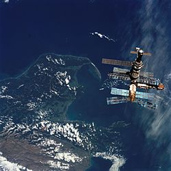
Mir in 1996 as seen from Space Shuttle Atlantis during STS-76.

However, the military influence over the Soviet space program may be the best explanation for this secrecy. The OKB-1 was subordinated under the Ministry of General Machine Building, tasked with the development of intercontinental ballistic missiles, and continued to give its assets random identifiers into the 1960s: "For example, the Vostok spacecraft was referred to as 'object IIF63' while its launch rocket was 'object 8K72K'". Soviet defense factories had been assigned numbers rather than names since 1927. Even these internal codes were obfuscated: in public, employees used a separate code, a set of special post-office numbers, to refer to the factories, institutes, and departments.

The program's public pronouncements were uniformly positive: as far as the people knew, the Soviet space program had never experienced failure. According to historian James Andrews, "With almost no exceptions, coverage of Soviet space exploits, especially in the case of human space missions, omitted reports of failure or trouble".

"The USSR was famously described by Winston Churchill as 'a riddle, wrapped in a mystery, inside an enigma' and nothing signified this more than the search for the truth behind its space program during the Cold War. Although the Space Race was literally played out above our heads, it was often obscured by a figurative 'space curtain' that took much effort to see through" says Dominic Phelan in the book Cold War Space Sleuths (Springer-Praxis 2013).

Microwave transmission

From Wikipedia, the free encyclopedia
https://en.wikipedia.org/wiki/Microwave_transmission
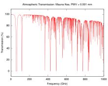
The atmospheric attenuation of microwaves in dry air with a precipitable water vapor level of 0.001 mm. The downward spikes in the graph corresponds to frequencies at which microwaves are absorbed more strongly, such as by oxygen molecules.

Microwave transmission is the transmission of information by electromagnetic waves with wavelengths in the microwave frequency range of 300MHz to 300GHz(1 m - 1 mm wavelength) of the electromagnetic spectrum. Microwave signals are normally limited to the line of sight, so long-distance transmission using these signals requires a series of repeaters forming a microwave relay network. It is possible to use microwave signals in over-the-horizon communications using tropospheric scatter, but such systems are expensive and generally used only in specialist roles.

Although an experimental 40-mile (64 km) microwave telecommunication link across the English Channel was demonstrated in 1931, the development of radar in World War II provided the technology for practical exploitation of microwave communication. During the war, the British Army introduced the Wireless Set No. 10, which used microwave relays to multiplex eight telephone channels over long distances. A link across the English Channel allowed General Bernard Montgomery to remain in continual contact with his group headquarters in London.

In the post-war era, the development of microwave technology was rapid, which led to the construction of several transcontinental microwave relay systems in North America and Europe. In addition to carrying thousands of telephone calls at a time, these networks were also used to send television signals for cross-country broadcast, and later, computer data. Communication satellites took over the television broadcast market during the 1970s and 80s, and the introduction of long-distance fibre optic systems in the 1980s and especially 90s led to the rapid rundown of the relay networks, most of which are abandoned.

In recent years, there has been an explosive increase in use of the microwave spectrum by new telecommunication technologies such as wireless networks, and direct-broadcast satellites which broadcast television and radio directly into consumers' homes. Larger line-of-sight links are once again popular for handing connections between mobile telephone towers, although these are generally not organized into long relay chains.

Uses

Microwaves are widely used for point-to-point communications because their small wavelength allows conveniently-sized antennas to direct them in narrow beams, which can be pointed directly at the receiving antenna. This allows nearby microwave equipment to use the same frequencies without interfering with each other, as lower frequency radio waves do. This frequency reuse conserves scarce radio spectrum bandwidth. Another advantage is that the high frequency of microwaves gives the microwave band a very large information-carrying capacity; the microwave band has a bandwidth 30 times that of all the rest of the radio spectrum below it. A disadvantage is that microwaves are limited to line of sight propagation; they cannot pass around hills or mountains as lower frequency radio waves can.

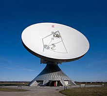
A parabolic satellite antenna for Erdfunkstelle Raisting, based in Raisting, Bavaria, Germany

Microwave radio transmission is commonly used in point-to-point communication systems on the surface of the Earth, in satellite communications, and in deep space radio communications. Other parts of the microwave radio band are used for radars, radio navigation systems, sensor systems, and radio astronomy.

The next higher frequency band of the radio spectrum, between 30 GHz and 300 GHz, are called "millimeter waves" because their wavelengths range from 10 mm to 1 mm. Radio waves in this band are strongly attenuated by the gases of the atmosphere. This limits their practical transmission distance to a few kilometers, so these frequencies cannot be used for long-distance communication. The electronic technologies needed in the millimeter wave band are also in an earlier state of development than those of the microwave band.

Wireless transmission of information

More recently, microwaves have been used for wireless power transmission.

Microwave radio relay

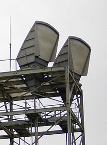
C-band horn-reflector antennas on the roof of a telephone switching center in Seattle, Washington, part of the U.S. AT&T Long Lines microwave relay network
Dozens of microwave dishes on the Heinrich-Hertz-Turm in Hamburg, Germany

Microwave radio relay is a technology widely used in the 1950s and 1960s for transmitting information, such as long-distance telephone calls and television programs between two terrestrial points on a narrow beam of microwaves. In microwave radio relay, a microwave transmitter and directional antenna transmits a narrow beam of microwaves carrying many channels of information on a line of sight path to another relay station where it is received by a directional antenna and receiver, forming a fixed radio connection between the two points. The link was often bidirectional, using a transmitter and receiver at each end to transmit data in both directions. The requirement of a line of sight limits the separation between stations to the visual horizon, about 30 to 50 miles (48 to 80 km). For longer distances, the receiving station could function as a relay, retransmitting the received information to another station along its journey. Chains of microwave relay stations were used to transmit telecommunication signals over transcontinental distances. Microwave relay stations were often located on tall buildings and mountaintops, with their antennas on towers to get maximum range.

Beginning in the 1950s, networks of microwave relay links, such as the AT&T Long Lines system in the U.S., carried long-distance telephone calls and television programs between cities. The first system, dubbed TDX and built by AT&T, connected New York and Boston in 1947 with a series of eight radio relay stations. Through the 1950s, they deployed a network of a slightly improved version across the U.S., known as TD2. These included long daisy-chained links that traversed mountain ranges and spanned continents. The launch of communication satellites in the 1970s provided a cheaper alternative. Much of the transcontinental traffic is now carried by satellites and optical fibers, but microwave relay remains important for shorter distances.

Planning

Communications tower on Frazier Mountain, Southern California with microwave relay dishes

Because the radio waves travel in narrow beams confined to a line-of-sight path from one antenna to the other, they do not interfere with other microwave equipment, so nearby microwave links can use the same frequencies. Antennas must be highly directional (high gain); these antennas are installed in elevated locations such as large radio towers in order to be able to transmit across long distances. Typical types of antenna used in radio relay link installations are parabolic antennas, dielectric lens, and horn-reflector antennas, which have a diameter of up to 4 meters. Highly directive antennas permit an economical use of the available frequency spectrum, despite long transmission distances.

Danish military radio relay node

Because of the high frequencies used, a line-of-sight path between the stations is required. Additionally, in order to avoid attenuation of the beam, an area around the beam called the first Fresnel zone must be free from obstacles. Obstacles in the signal field cause unwanted attenuation. High mountain peak or ridge positions are often ideal.

In addition to conventional repeaters which use back-to-back radios transmitting on different frequencies, obstructions in microwave paths can be dealt with by using Passive repeater or on-frequency repeaters.

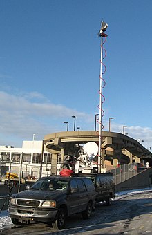
Production truck used for remote broadcasts by television news has a microwave dish on a retractible telescoping mast to transmit live video back to the studio.

Obstacles, the curvature of the Earth, the geography of the area and reception issues arising from the use of nearby land (such as in manufacturing and forestry) are important issues to consider when planning radio links. In the planning process, it is essential that "path profiles" are produced, which provide information about the terrain and Fresnel zones affecting the transmission path. The presence of a water surface, such as a lake or river, along the path also must be taken into consideration since it can reflect the beam, and the direct and reflected beam can interfere at the receiving antenna, causing multipath fading. Multipath fades are usually deep only in a small spot and a narrow frequency band, so space and/or frequency diversity schemes can be applied to mitigate these effects.

The effects of atmospheric stratification cause the radio path to bend downward in a typical situation so a major distance is possible as the earth equivalent curvature increases from 6370 km to about 8500 km (a 4/3 equivalent radius effect). Rare events of temperature, humidity and pressure profile versus height, may produce large deviations and distortion of the propagation and affect transmission quality. High-intensity rain and snow making rain fade must also be considered as an impairment factor, especially at frequencies above 10 GHz. All previous factors, collectively known as path loss, make it necessary to compute suitable power margins, in order to maintain the link operative for a high percentage of time, like the standard 99.99% or 99.999% used in 'carrier class' services of most telecommunication operators.

The longest microwave radio relay known up to date crosses the Red Sea with a 360 km (200 mi) hop between Jebel Erba (2170m a.s.l., 20°44′46.17″N 36°50′24.65″E, Sudan) and Jebel Dakka (2572m a.s.l., 21°5′36.89″N 40°17′29.80″E, Saudi Arabia). The link was built in 1979 by Telettra to transmit 300 telephone channels and one TV signal, in the 2 GHz frequency band. (Hop distance is the distance between two microwave stations).

Previous considerations represent typical problems characterizing terrestrial radio links using microwaves for the so-called backbone networks: hop lengths of a few tens of kilometers (typically 10 to 60 km) were largely used until the 1990s. Frequency bands below 10 GHz, and above all, the information to be transmitted, were a stream containing a fixed capacity block. The target was to supply the requested availability for the whole block (Plesiochronous digital hierarchy, PDH, or synchronous digital hierarchy, SDH). Fading and/or multipath affecting the link for short time period during the day had to be counteracted by the diversity architecture. During 1990s microwave radio links begun widely to be used for urban links in cellular network. Requirements regarding link distance changed to shorter hops (less than 10 km, typically 3 to 5 km), and frequency increased to bands between 11 and 43 GHz and more recently, up to 86 GHz (E-band). Furthermore, link planning deals more with intense rainfall and less with multipath, so diversity schemes became less used. Another big change that occurred during the last decade was an evolution toward packet radio transmission. Therefore, new countermeasures, such as adaptive modulation, have been adopted.

The emitted power is regulated for cellular and microwave systems. These microwave transmissions use emitted power typically from 0.03 to 0.30 W, radiated by a parabolic antenna on a narrow beam diverging by a few degrees (1 to 3-4). The microwave channel arrangement is regulated by International Telecommunication Union (ITU-R) and local regulations (ETSI, FCC). In the last decade the dedicated spectrum for each microwave band has become extremely crowded, motivating the use of techniques to increase transmission capacity such as frequency reuse, polarization-division multiplexing, XPIC, MIMO.

History

Antennas of 1931 experimental 1.7 GHz microwave relay link across the English Channel. The receiving antenna (background, right) was located behind the transmitting antenna to avoid interference.
US Army Signal Corps portable microwave relay station, 1945. Microwave relay systems were first developed in World War II for secure military communication.

The history of radio relay communication began in 1898 from the publication by Johann Mattausch in Austrian journal, Zeitschrift für Electrotechnik. But his proposal was primitive and not suitable for practical use. The first experiments with radio repeater stations to relay radio signals were done in 1899 by Emile Guarini-Foresio. However the low frequency and medium frequency radio waves used during the first 40 years of radio proved to be able to travel long distances by ground wave and skywave propagation. The need for radio relay did not really begin until the 1940s exploitation of microwaves, which traveled by line of sight and so were limited to a propagation distance of about 40 miles (64 km) by the visual horizon.

In 1931 an Anglo-French consortium headed by Andre C. Clavier demonstrated an experimental microwave relay link across the English Channel using 10-foot (3 m) dishes. Telephony, telegraph, and facsimile data was transmitted over the bidirectional 1.7 GHz beams 40 miles (64 km) between Dover, UK, and Calais, France. The radiated power, produced by a miniature Barkhausen–Kurz tube located at the dish's focus, was one-half watt. A 1933 military microwave link between airports at St. Inglevert, France, and Lympne, UK, a distance of 56 km (35 miles), was followed in 1935 by a 300 MHz telecommunication link, the first commercial microwave relay system.

The development of radar during World War II provided much of the microwave technology which made practical microwave communication links possible, particularly the klystron oscillator and techniques of designing parabolic antennas. Though not commonly known, the British Army used the Wireless Set Number 10 in this role during World War II.

After the war, telephone companies used this technology to build large microwave radio relay networks to carry long-distance telephone calls. During the 1950s a unit of the US telephone carrier, AT&T Long Lines, built a transcontinental system of microwave relay links across the US that grew to carry the majority of US long distance telephone traffic, as well as television network signals. The main motivation in 1946 to use microwave radio instead of cable was that a large capacity could be installed quickly and at less cost. It was expected at that time that the annual operating costs for microwave radio would be greater than for cable. There were two main reasons that a large capacity had to be introduced suddenly: Pent up demand for long-distance telephone service, because of the hiatus during the war years, and the new medium of television, which needed more bandwidth than radio. The prototype was called TDX and was tested with a connection between New York City and Murray Hill, the location of Bell Laboratories in 1946. The TDX system was set up between New York and Boston in 1947. The TDX was upgraded to the TD2 system, which used [the Morton tube, 416B and later 416C, manufactured by Western Electric] in the transmitters, and then later to TD3 that used solid-state electronics.

Richtfunkstelle Berlin-Frohnau

Remarkable were the microwave relay links to West Berlin during the Cold War, which had to be built and operated due to the large distance between West Germany and Berlin at the edge of the technical feasibility. In addition to the telephone network, also microwave relay links for the distribution of TV and radio broadcasts. This included connections from the studios to the broadcasting systems distributed across the country, as well as between the radio stations, for example for program exchange.

Military microwave relay systems continued to be used into the 1960s, when many of these systems were supplanted with tropospheric scatter or communication satellite systems. When the NATO military arm was formed, much of this existing equipment was transferred to communications groups. The typical communications systems used by NATO during that time period consisted of the technologies which had been developed for use by the telephone carrier entities in host countries. One example from the USA is the RCA CW-20A 1–2 GHz microwave relay system which utilized flexible UHF cable rather than the rigid waveguide required by higher frequency systems, making it ideal for tactical applications. The typical microwave relay installation or portable van had two radio systems (plus backup) connecting two line of sight sites. These radios would often carry 24 telephone channels frequency-division multiplexed on the microwave carrier (i.e. Lenkurt 33C FDM). Any channel could be designated to carry up to 18 teletype communications instead. Similar systems from Germany and other member nations were also in use.

Long-distance microwave relay networks were built in many countries until the 1980s, when the technology lost its share of fixed operation to newer technologies such as fiber-optic cable and communication satellites, which offer a lower cost per bit.

Microwave spying

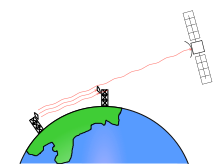
During the Cold War, the US intelligence agencies, such as the National Security Agency (NSA), were reportedly able to intercept Soviet microwave traffic using satellites such as Rhyolite. Much of the beam of a microwave link passes the receiving antenna and radiates toward the horizon, into space. By positioning a geosynchronous satellite in the path of the beam, the microwave beam can be received.

At the turn of the century, microwave radio relay systems are being used increasingly in portable radio applications. The technology is particularly suited to this application because of lower operating costs, a more efficient infrastructure, and provision of direct hardware access to the portable radio operator.

Microwave link

A microwave link is a communications system that uses a beam of radio waves in the microwave frequency range to transmit video, audio, or data between two locations, which can be from just a few feet or meters to several miles or kilometers apart. Microwave links are commonly used by television broadcasters to transmit programmes across a country, for instance, or from an outside broadcast back to a studio.

Mobile units can be camera mounted, allowing cameras the freedom to move around without trailing cables. These are often seen on the touchlines of sports fields on Steadicam systems.

Properties of microwave links

  • Involve line of sight (LOS) communication technology
  • Affected greatly by environmental constraints, including rain fade
  • Have very limited penetration capabilities through obstacles such as hills, buildings and trees
  • Sensitive to high pollen count
  • Signals can be degraded during Solar proton events

Uses of microwave links

  • In communications between satellites and base stations
  • As backbone carriers for cellular systems
  • In short-range indoor communications
  • Linking remote and regional telephone exchanges to larger (main) exchanges without the need for copper/optical fibre lines
  • Measuring the intensity of rain between two locations

Troposcatter

Terrestrial microwave relay links are limited in distance to the visual horizon, a few tens of miles or kilometers depending on tower height. Tropospheric scatter ("troposcatter" or "scatter") was a technology developed in the 1950s to allow microwave communication links beyond the horizon, to a range of several hundred kilometers. The transmitter radiates a beam of microwaves into the sky, at a shallow angle above the horizon toward the receiver. As the beam passes through the troposphere a small fraction of the microwave energy is scattered back toward the ground by water vapor and dust in the air. A sensitive receiver beyond the horizon picks up this reflected signal. Signal clarity obtained by this method depends on the weather and other factors, and as a result, a high level of technical difficulty is involved in the creation of a reliable over horizon radio relay link. Troposcatter links are therefore only used in special circumstances where satellites and other long-distance communication channels cannot be relied on, such as in military communications.

Ego depletion

From Wikipedia, the free encyclopedia https://en.wikipedia.org/wiki/Ego_depletion ...