Nonlinear optics (NLO) is the branch of optics that describes the behaviour of light in nonlinear media, that is, media in which the polarization density P responds non-linearly to the electric field E of the light. The non-linearity is typically observed only at very high light intensities (values of atomic electric fields, typically 108 V/m) such as those provided by lasers. Above the Schwinger limit, the vacuum itself is expected to become nonlinear. In nonlinear optics, the superposition principle no longer holds.
History
The first nonlinear optical effect to be predicted was two-photon absorption, by Maria Goeppert Mayer for her PhD in 1931, but it remained an unexplored theoretical curiosity until 1961 and the almost simultaneous observation of two-photon absorption at Bell Labs and the discovery of second-harmonic generation by Peter Franken et al. at University of Michigan, both shortly after the construction of the first laser by Theodore Maiman. However, some nonlinear effects were discovered before the development of the laser. The theoretical basis for many nonlinear processes were first described in Bloembergen's monograph "Nonlinear Optics".
Nonlinear optical processes
Nonlinear optics explains nonlinear response of properties such as frequency, polarization, phase or path of incident light. These nonlinear interactions give rise to a host of optical phenomena:
Frequency-mixing processes
- Second-harmonic generation (SHG), or frequency doubling, generation of light with a doubled frequency (half the wavelength), two photons are destroyed, creating a single photon at two times the frequency.
- Third-harmonic generation (THG), generation of light with a tripled frequency (one-third the wavelength), three photons are destroyed, creating a single photon at three times the frequency.
- High-harmonic generation (HHG), generation of light with frequencies much greater than the original (typically 100 to 1000 times greater).
- Sum-frequency generation (SFG), generation of light with a frequency that is the sum of two other frequencies (SHG is a special case of this).
- Difference-frequency generation (DFG), generation of light with a frequency that is the difference between two other frequencies.
- Optical parametric amplification (OPA), amplification of a signal input in the presence of a higher-frequency pump wave, at the same time generating an idler wave (can be considered as DFG).
- Optical parametric oscillation (OPO), generation of a signal and idler wave using a parametric amplifier in a resonator (with no signal input).
- Optical parametric generation (OPG), like parametric oscillation but without a resonator, using a very high gain instead.
- Half-harmonic generation, the special case of OPO or OPG when the signal and idler degenerate in one single frequency,
- Spontaneous parametric down-conversion (SPDC), the amplification of the vacuum fluctuations in the low-gain regime.
- Optical rectification (OR), generation of quasi-static electric fields.
- Nonlinear light-matter interaction with free electrons and plasmas.
Other nonlinear processes
- Optical Kerr effect, intensity-dependent refractive index (a effect).
- Self-focusing, an effect due to the optical Kerr effect (and possibly higher-order nonlinearities) caused by the spatial variation in the intensity creating a spatial variation in the refractive index.
- Kerr-lens modelocking (KLM), the use of self-focusing as a mechanism to mode-lock laser.
- Self-phase modulation (SPM), an effect due to the optical Kerr effect (and possibly higher-order nonlinearities) caused by the temporal variation in the intensity creating a temporal variation in the refractive index.
- Optical solitons, an equilibrium solution for either an optical pulse (temporal soliton) or spatial mode (spatial soliton) that does not change during propagation due to a balance between dispersion and the Kerr effect (e.g. self-phase modulation for temporal and self-focusing for spatial solitons).
- Self-diffraction, splitting of beams in a multi-wave mixing process with potential energy transfer.
- Cross-phase modulation (XPM), where one wavelength of light can affect the phase of another wavelength of light through the optical Kerr effect.
- Four-wave mixing (FWM), can also arise from other nonlinearities.
- Cross-polarized wave generation (XPW), a effect in which a wave with polarization vector perpendicular to the input one is generated.
- Modulational instability.
- Raman amplification
- Optical phase conjugation.
- Stimulated Brillouin scattering, interaction of photons with acoustic phonons
- Multi-photon absorption, simultaneous absorption of two or more photons, transferring the energy to a single electron.
- Multiple photoionisation, near-simultaneous removal of many bound electrons by one photon.
- Chaos in optical systems.
Related processes
In these processes, the medium has a linear response to the light, but the properties of the medium are affected by other causes:
- Pockels effect, the refractive index is affected by a static electric field; used in electro-optic modulators.
- Acousto-optics, the refractive index is affected by acoustic waves (ultrasound); used in acousto-optic modulators.
- Raman scattering, interaction of photons with optical phonons.
Parametric processes
Nonlinear effects fall into two qualitatively different categories, parametric and non-parametric effects. A parametric non-linearity is an interaction in which the quantum state of the nonlinear material is not changed by the interaction with the optical field. As a consequence of this, the process is "instantaneous". Energy and momentum are conserved in the optical field, making phase matching important and polarization-dependent.
Theory
Parametric and "instantaneous" (i.e. material must be lossless and dispersionless through the Kramers–Kronig relations) nonlinear optical phenomena, in which the optical fields are not too large, can be described by a Taylor series expansion of the dielectric polarization density (electric dipole moment per unit volume) P(t) at time t in terms of the electric field E(t):
where the coefficients χ(n) are the n-th-order susceptibilities of the medium, and the presence of such a term is generally referred to as an n-th-order nonlinearity. Note that the polarization density P(t) and electrical field E(t) are considered as scalar for simplicity. In general, χ(n) is an (n + 1)-th-rank tensor representing both the polarization-dependent nature of the parametric interaction and the symmetries (or lack) of the nonlinear material.
Wave equation in a nonlinear material
Central to the study of electromagnetic waves is the wave equation. Starting with Maxwell's equations in an isotropic space, containing no free charge, it can be shown that
where PNL is the nonlinear part of the polarization density, and n is the refractive index, which comes from the linear term in P.
Note that one can normally use the vector identity
and Gauss's law (assuming no free charges, ),
to obtain the more familiar wave equation
For a nonlinear medium, Gauss's law does not imply that the identity
is true in general, even for an isotropic medium. However, even when this term is not identically 0, it is often negligibly small and thus in practice is usually ignored, giving us the standard nonlinear wave equation:
Nonlinearities as a wave-mixing process
The nonlinear wave equation is an inhomogeneous differential equation. The general solution comes from the study of ordinary differential equations and can be obtained by the use of a Green's function. Physically one gets the normal electromagnetic wave solutions to the homogeneous part of the wave equation:
and the inhomogeneous term
acts as a driver/source of the electromagnetic waves. One of the consequences of this is a nonlinear interaction that results in energy being mixed or coupled between different frequencies, which is often called a "wave mixing".
In general, an n-th order nonlinearity will lead to (n + 1)-wave mixing. As an example, if we consider only a second-order nonlinearity (three-wave mixing), then the polarization P takes the form
If we assume that E(t) is made up of two components at frequencies ω1 and ω2, we can write E(t) as
and using Euler's formula to convert to exponentials,
where "c.c." stands for complex conjugate. Plugging this into the expression for P gives
which has frequency components at 2ω1, 2ω2, ω1 + ω2, ω1 − ω2, and 0. These three-wave mixing processes correspond to the nonlinear effects known as second-harmonic generation, sum-frequency generation, difference-frequency generation and optical rectification respectively.
Note: Parametric generation and amplification is a variation of difference-frequency generation, where the lower frequency of one of the two generating fields is much weaker (parametric amplification) or completely absent (parametric generation). In the latter case, the fundamental quantum-mechanical uncertainty in the electric field initiates the process.
Phase matching
The above ignores the position dependence of the electrical fields. In a typical situation, the electrical fields are traveling waves described by
at position , with the wave vector , where is the velocity of light in vacuum, and is the index of refraction of the medium at angular frequency . Thus, the second-order polarization at angular frequency is
At each position within the nonlinear medium, the oscillating second-order polarization radiates at angular frequency and a corresponding wave vector . Constructive interference, and therefore a high-intensity field, will occur only if
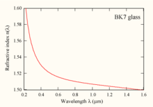
The above equation is known as the phase-matching condition. Typically, three-wave mixing is done in a birefringent crystalline material, where the refractive index depends on the polarization and direction of the light that passes through. The polarizations of the fields and the orientation of the crystal are chosen such that the phase-matching condition is fulfilled. This phase-matching technique is called angle tuning. Typically a crystal has three axes, one or two of which have a different refractive index than the other one(s). Uniaxial crystals, for example, have a single preferred axis, called the extraordinary (e) axis, while the other two are ordinary axes (o) (see crystal optics). There are several schemes of choosing the polarizations for this crystal type. If the signal and idler have the same polarization, it is called "type-I phase matching", and if their polarizations are perpendicular, it is called "type-II phase matching". However, other conventions exist that specify further which frequency has what polarization relative to the crystal axis. These types are listed below, with the convention that the signal wavelength is shorter than the idler wavelength.
| Polarizations | Scheme | ||
|---|---|---|---|
| Pump | Signal | Idler | |
| e | o | o | Type I |
| e | o | e | Type II (or IIA) |
| e | e | o | Type III (or IIB) |
| e | e | e | Type IV |
| o | o | o | Type V (or type 0, or "zero") |
| o | o | e | Type VI (or IIB or IIIA) |
| o | e | o | Type VII (or IIA or IIIB) |
| o | e | e | Type VIII (or I) |
Most common nonlinear crystals are negative uniaxial, which means that the e axis has a smaller refractive index than the o axes. In those crystals, type-I and -II phase matching are usually the most suitable schemes. In positive uniaxial crystals, types VII and VIII are more suitable. Types II and III are essentially equivalent, except that the names of signal and idler are swapped when the signal has a longer wavelength than the idler. For this reason, they are sometimes called IIA and IIB. The type numbers V–VIII are less common than I and II and variants.
One undesirable effect of angle tuning is that the optical frequencies involved do not propagate collinearly with each other. This is due to the fact that the extraordinary wave propagating through a birefringent crystal possesses a Poynting vector that is not parallel to the propagation vector. This would lead to beam walk-off, which limits the nonlinear optical conversion efficiency. Two other methods of phase matching avoid beam walk-off by forcing all frequencies to propagate at a 90° with respect to the optical axis of the crystal. These methods are called temperature tuning and quasi-phase-matching.
Temperature tuning is used when the pump (laser) frequency polarization is orthogonal to the signal and idler frequency polarization. The birefringence in some crystals, in particular lithium niobate is highly temperature-dependent. The crystal temperature is controlled to achieve phase-matching conditions.
The other method is quasi-phase-matching. In this method the frequencies involved are not constantly locked in phase with each other, instead the crystal axis is flipped at a regular interval Λ, typically 15 micrometres in length. Hence, these crystals are called periodically poled. This results in the polarization response of the crystal to be shifted back in phase with the pump beam by reversing the nonlinear susceptibility. This allows net positive energy flow from the pump into the signal and idler frequencies. In this case, the crystal itself provides the additional wavevector k = 2π/Λ (and hence momentum) to satisfy the phase-matching condition. Quasi-phase-matching can be expanded to chirped gratings to get more bandwidth and to shape an SHG pulse like it is done in a dazzler. SHG of a pump and self-phase modulation (emulated by second-order processes) of the signal and an optical parametric amplifier can be integrated monolithically.
Higher-order frequency mixing
The above holds for processes. It can be extended for processes where is nonzero, something that is generally true in any medium without any symmetry restrictions; in particular resonantly enhanced sum or difference frequency mixing in gasses is frequently used for extreme or "vacuum" Ultra Violet light generation. In common scenarios, such as mixing in dilute gases, the non-linearity is weak and so the light beams are focused which, unlike the plane wave approximation used above, introduces a pi phase shift on each light beam, complicating the phase matching requirements. Conveniently, difference frequency mixing with cancels this focal phase shift and often has a nearly self-canceling overall phase matching condition, which relatively simplifies broad wavelength tuning compared to sum frequency generation. In all four frequencies are mixing simultaneously, as opposed to sequential mixing via two processes.
The Kerr effect can be described as a as well. At high peak powers the Kerr effect can cause filamentation of light in air, in which the light travels without dispersion or divergence in a self-generated waveguide. At even high intensities the Taylor series, which led the domination of the lower orders, does not converge anymore and instead a time based model is used. When a noble gas atom is hit by an intense laser pulse, which has an electric field strength comparable to the Coulomb field of the atom, the outermost electron may be ionized from the atom. Once freed, the electron can be accelerated by the electric field of the light, first moving away from the ion, then back toward it as the field changes direction. The electron may then recombine with the ion, releasing its energy in the form of a photon. The light is emitted at every peak of the laser light field which is intense enough, producing a series of attosecond light flashes. The photon energies generated by this process can extend past the 800th harmonic order up to a few KeV. This is called high-order harmonic generation. The laser must be linearly polarized, so that the electron returns to the vicinity of the parent ion. High-order harmonic generation has been observed in noble gas jets, cells, and gas-filled capillary waveguides.
Example uses
Frequency doubling
One of the most commonly used frequency-mixing processes is frequency doubling, or second-harmonic generation. With this technique, the 1064 nm output from Nd:YAG lasers or the 800 nm output from Ti:sapphire lasers can be converted to visible light, with wavelengths of 532 nm (green) or 400 nm (violet) respectively.
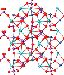
Practically, frequency doubling is carried out by placing a nonlinear medium in a laser beam. While there are many types of nonlinear media, the most common media are crystals. Commonly used crystals are BBO (β-barium borate), KDP (potassium dihydrogen phosphate), KTP (potassium titanyl phosphate), and lithium niobate. These crystals have the necessary properties of being strongly birefringent (necessary to obtain phase matching, see below), having a specific crystal symmetry, being transparent for both the impinging laser light and the frequency-doubled wavelength, and having high damage thresholds, which makes them resistant against the high-intensity laser light.
Optical phase conjugation
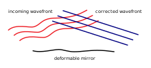
It is possible, using nonlinear optical processes, to exactly reverse the propagation direction and phase variation of a beam of light. The reversed beam is called a conjugate beam, and thus the technique is known as optical phase conjugation (also called time reversal, wavefront reversal and is significantly different from retroreflection).
A device producing the phase-conjugation effect is known as a phase-conjugate mirror (PCM).
Principles
One can interpret optical phase conjugation as being analogous to a real-time holographic process. In this case, the interacting beams simultaneously interact in a nonlinear optical material to form a dynamic hologram (two of the three input beams), or real-time diffraction pattern, in the material. The third incident beam diffracts at this dynamic hologram, and, in the process, reads out the phase-conjugate wave. In effect, all three incident beams interact (essentially) simultaneously to form several real-time holograms, resulting in a set of diffracted output waves that phase up as the "time-reversed" beam. In the language of nonlinear optics, the interacting beams result in a nonlinear polarization within the material, which coherently radiates to form the phase-conjugate wave.
Reversal of wavefront means a perfect reversal of photons' linear momentum and angular momentum. The reversal of angular momentum means reversal of both polarization state and orbital angular momentum. Reversal of orbital angular momentum of optical vortex is due to the perfect match of helical phase profiles of the incident and reflected beams. Optical phase conjugation is implemented via stimulated Brillouin scattering, four-wave mixing, three-wave mixing, static linear holograms and some other tools.
The most common way of producing optical phase conjugation is to use a four-wave mixing technique, though it is also possible to use processes such as stimulated Brillouin scattering.
Four-wave mixing technique
For the four-wave mixing technique, we can describe four beams (j = 1, 2, 3, 4) with electric fields:
where Ej are the electric field amplitudes. Ξ1 and Ξ2 are known as the two pump waves, with Ξ3 being the signal wave, and Ξ4 being the generated conjugate wave.
If the pump waves and the signal wave are superimposed in a medium with a non-zero χ(3), this produces a nonlinear polarization field:
resulting in generation of waves with frequencies given by ω = ±ω1 ± ω2 ± ω3 in addition to third-harmonic generation waves with ω = 3ω1, 3ω2, 3ω3.
As above, the phase-matching condition determines which of these waves is the dominant. By choosing conditions such that ω = ω1 + ω2 − ω3 and k = k1 + k2 − k3, this gives a polarization field:
This is the generating field for the phase-conjugate beam, Ξ4. Its direction is given by k4 = k1 + k2 − k3, and so if the two pump beams are counterpropagating (k1 = −k2), then the conjugate and signal beams propagate in opposite directions (k4 = −k3). This results in the retroreflecting property of the effect.
Further, it can be shown that for a medium with refractive index n and a beam interaction length l, the electric field amplitude of the conjugate beam is approximated by
where c is the speed of light. If the pump beams E1 and E2 are plane (counterpropagating) waves, then
that is, the generated beam amplitude is the complex conjugate of the signal beam amplitude. Since the imaginary part of the amplitude contains the phase of the beam, this results in the reversal of phase property of the effect.
Note that the constant of proportionality between the signal and conjugate beams can be greater than 1. This is effectively a mirror with a reflection coefficient greater than 100%, producing an amplified reflection. The power for this comes from the two pump beams, which are depleted by the process.
The frequency of the conjugate wave can be different from that of the signal wave. If the pump waves are of frequency ω1 = ω2 = ω, and the signal wave is higher in frequency such that ω3 = ω + Δω, then the conjugate wave is of frequency ω4 = ω − Δω. This is known as frequency flipping.
Angular and linear momenta in optical phase conjugation
Classical picture
In classical Maxwell electrodynamics a phase-conjugating mirror performs reversal of the Poynting vector:
("in" means incident field, "out" means reflected field) where
which is a linear momentum density of electromagnetic field. In the same way a phase-conjugated wave has an opposite angular momentum density vector with respect to incident field:
The above identities are valid locally, i.e. in each space point in a given moment for an ideal phase-conjugating mirror.
Quantum picture
In quantum electrodynamics the photon with energy also possesses linear momentum and angular momentum, whose projection on propagation axis is , where is topological charge of photon, or winding number, is propagation axis. The angular momentum projection on propagation axis has discrete values .
In quantum electrodynamics the interpretation of phase conjugation is much simpler compared to classical electrodynamics. The photon reflected from phase conjugating-mirror (out) has opposite directions of linear and angular momenta with respect to incident photon (in):
Nonlinear optical pattern formation
Optical fields transmitted through nonlinear Kerr media can also display pattern formation owing to the nonlinear medium amplifying spatial and temporal noise. The effect is referred to as optical modulation instability. This has been observed both in photo-refractive, photonic lattices, as well as photo-reactive systems. In the latter case, optical nonlinearity is afforded by reaction-induced increases in refractive index. Examples of pattern formation are spatial solitons and vortex lattices in framework of Nonlinear Schrödinger equation.
Molecular nonlinear optics
The early studies of nonlinear optics and materials focused on the inorganic solids. With the development of nonlinear optics, molecular optical properties were investigated, forming molecular nonlinear optics. The traditional approaches used in the past to enhance nonlinearities include extending chromophore π-systems, adjusting bond length alternation, inducing intramolecular charge transfer, extending conjugation in 2D, and engineering multipolar charge distributions. Recently, many novel directions were proposed for enhanced nonlinearity and light manipulation, including twisted chromophores, combining rich density of states with bond alternation, microscopic cascading of second-order nonlinearity, etc. Due to the distinguished advantages, molecular nonlinear optics have been widely used in the biophotonics field, including bioimaging, phototherapy, biosensing, etc.
Common SHG materials
Ordered by pump wavelength:
- 800 nm: BBO
- 806 nm: lithium iodate (LiIO3)
- 860 nm: potassium niobate (KNbO3)
- 980 nm: KNbO3
- 1064 nm: monopotassium phosphate (KH2PO4, KDP), lithium triborate (LBO) and β-barium borate (BBO)
- 1300 nm: gallium selenide (GaSe)
- 1319 nm: KNbO3, BBO, KDP, potassium titanyl phosphate (KTP), lithium niobate (LiNbO3), LiIO3, and ammonium dihydrogen phosphate (ADP)
- 1550 nm: potassium titanyl phosphate (KTP), lithium niobate (LiNbO3)




![{\displaystyle P^{(2)}(\mathbf {x} ,t)\propto E_{1}^{n_{1}}E_{2}^{n_{2}}e^{i[(\mathbf {k} _{1}+\mathbf {k} _{2})\cdot \mathbf {x} -\omega _{3}t]}+{\text{c.c.}}}](https://wikimedia.org/api/rest_v1/media/math/render/svg/6229621c7fa6db119f6025366e86c366241399a3)


