Search This Blog

Thursday, June 30, 2022

Analog-to-digital converter

From Wikipedia, the free encyclopedia

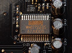
4-channel stereo multiplexed analog-to-digital converter WM8775SEDS made by Wolfson Microelectronics placed on an X-Fi Fatal1ty Pro sound card
 
AD570 8-bit successive-approximation analog-to-digital converter
 
AD570/AD571 silicon die
 
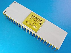
INTERSIL ICL7107. 31/2 digit single-chip A/D converter
 
ICL7107 silicon die

In electronics, an analog-to-digital converter (ADC, A/D, or A-to-D) is a system that converts an analog signal, such as a sound picked up by a microphone or light entering a digital camera, into a digital signal. An ADC may also provide an isolated measurement such as an electronic device that converts an analog input voltage or current to a digital number representing the magnitude of the voltage or current. Typically the digital output is a two's complement binary number that is proportional to the input, but there are other possibilities.

There are several ADC architectures. Due to the complexity and the need for precisely matched components, all but the most specialized ADCs are implemented as integrated circuits (ICs). These typically take the form of metal–oxide–semiconductor (MOS) mixed-signal integrated circuit chips that integrate both analog and digital circuits.

A digital-to-analog converter (DAC) performs the reverse function; it converts a digital signal into an analog signal.

Explanation

An ADC converts a continuous-time and continuous-amplitude analog signal to a discrete-time and discrete-amplitude digital signal. The conversion involves quantization of the input, so it necessarily introduces a small amount of error or noise. Furthermore, instead of continuously performing the conversion, an ADC does the conversion periodically, sampling the input, limiting the allowable bandwidth of the input signal.

The performance of an ADC is primarily characterized by its bandwidth and signal-to-noise ratio (SNR). The bandwidth of an ADC is characterized primarily by its sampling rate. The SNR of an ADC is influenced by many factors, including the resolution, linearity and accuracy (how well the quantization levels match the true analog signal), aliasing and jitter. The SNR of an ADC is often summarized in terms of its effective number of bits (ENOB), the number of bits of each measure it returns that are on average not noise. An ideal ADC has an ENOB equal to its resolution. ADCs are chosen to match the bandwidth and required SNR of the signal to be digitized. If an ADC operates at a sampling rate greater than twice the bandwidth of the signal, then per the Nyquist–Shannon sampling theorem, perfect reconstruction is possible. The presence of quantization error limits the SNR of even an ideal ADC. However, if the SNR of the ADC exceeds that of the input signal, its effects may be neglected resulting in an essentially perfect digital representation of the analog input signal.

Resolution

Fig. 1. An 8-level ADC coding scheme

The resolution of the converter indicates the number of different, ie discrete, values it can produce over the allowed range of analog input values. Thus a particular resolution determines the magnitude of the quantization error and therefore determines the maximum possible signal-to-noise ratio for an ideal ADC without the use of oversampling. The input samples are usually stored electronically in binary form within the ADC, so the resolution is usually expressed as the audio bit depth. In consequence, the number of discrete values available is usually a power of two. For example, an ADC with a resolution of 8 bits can encode an analog input to one in 256 different levels (28 = 256). The values can represent the ranges from 0 to 255 (i.e. as unsigned integers) or from −128 to 127 (i.e. as signed integer), depending on the application.

Resolution can also be defined electrically, and expressed in volts. The change in voltage required to guarantee a change in the output code level is called the least significant bit (LSB) voltage. The resolution Q of the ADC is equal to the LSB voltage. The voltage resolution of an ADC is equal to its overall voltage measurement range divided by the number of intervals:

where M is the ADC's resolution in bits and EFSR is the full scale voltage range (also called 'span'). EFSR is given by

where VRefHi and VRefLow are the upper and lower extremes, respectively, of the voltages that can be coded.

Normally, the number of voltage intervals is given by

where M is the ADC's resolution in bits.

That is, one voltage interval is assigned in between two consecutive code levels.

Example:

  • Coding scheme as in figure 1
  • Full scale measurement range = 0 to 1 volt
  • ADC resolution is 3 bits: 23 = 8 quantization levels (codes)
  • ADC voltage resolution, Q = 1 V / 8 = 0.125 V.

In many cases, the useful resolution of a converter is limited by the signal-to-noise ratio (SNR) and other errors in the overall system expressed as an ENOB.

Comparison of quantizing a sinusoid to 64 levels (6 bits) and 256 levels (8 bits). The additive noise created by 6-bit quantization is 12 dB greater than the noise created by 8-bit quantization. When the spectral distribution is flat, as in this example, the 12 dB difference manifests as a measurable difference in the noise floors.

Quantization error

Analog to digital conversion as shown with fig. 1 and fig. 2.

Quantization error is introduced by the quantization inherent in an ideal ADC. It is a rounding error between the analog input voltage to the ADC and the output digitized value. The error is nonlinear and signal-dependent. In an ideal ADC, where the quantization error is uniformly distributed between −1/2 LSB and +1/2 LSB, and the signal has a uniform distribution covering all quantization levels, the Signal-to-quantization-noise ratio (SQNR) is given by

where Q is the number of quantization bits. For example, for a 16-bit ADC, the quantization error is 96.3 dB below the maximum level.

Quantization error is distributed from DC to the Nyquist frequency. Consequently, if part of the ADC's bandwidth is not used, as is the case with oversampling, some of the quantization error will occur out-of-band, effectively improving the SQNR for the bandwidth in use. In an oversampled system, noise shaping can be used to further increase SQNR by forcing more quantization error out of band.

Dither

In ADCs, performance can usually be improved using dither. This is a very small amount of random noise (e.g. white noise), which is added to the input before conversion. Its effect is to randomize the state of the LSB based on the signal. Rather than the signal simply getting cut off altogether at low levels, it extends the effective range of signals that the ADC can convert, at the expense of a slight increase in noise. Note that dither can only increase the resolution of a sampler. It cannot improve the linearity, and thus accuracy does not necessarily improve.

Quantization distortion in an audio signal of very low level with respect to the bit depth of the ADC is correlated with the signal and sounds distorted and unpleasant. With dithering, the distortion is transformed into noise. The undistorted signal may be recovered accurately by averaging over time. Dithering is also used in integrating systems such as electricity meters. Since the values are added together, the dithering produces results that are more exact than the LSB of the analog-to-digital converter.

Dither is often applied when quantizing photographic images to a fewer number of bits per pixel—the image becomes noisier but to the eye looks far more realistic than the quantized image, which otherwise becomes banded. This analogous process may help to visualize the effect of dither on an analog audio signal that is converted to digital.

Accuracy

An ADC has several sources of errors. Quantization error and (assuming the ADC is intended to be linear) non-linearity are intrinsic to any analog-to-digital conversion. These errors are measured in a unit called the least significant bit (LSB). In the above example of an eight-bit ADC, an error of one LSB is 1/256 of the full signal range, or about 0.4%.

Nonlinearity

All ADCs suffer from nonlinearity errors caused by their physical imperfections, causing their output to deviate from a linear function (or some other function, in the case of a deliberately nonlinear ADC) of their input. These errors can sometimes be mitigated by calibration, or prevented by testing. Important parameters for linearity are integral nonlinearity and differential nonlinearity. These nonlinearities introduce distortion that can reduce the signal-to-noise ratio performance of the ADC and thus reduce its effective resolution.

Jitter

When digitizing a sine wave , the use of a non-ideal sampling clock will result in some uncertainty in when samples are recorded. Provided that the actual sampling time uncertainty due to clock jitter is , the error caused by this phenomenon can be estimated as . This will result in additional recorded noise that will reduce the effective number of bits (ENOB) below that predicted by quantization error alone. The error is zero for DC, small at low frequencies, but significant with signals of high amplitude and high frequency. The effect of jitter on performance can be compared to quantization error: , where q is the number of ADC bits.

Output size
(bits)
Signal Frequency
1 Hz 1 kHz 10 kHz 1 MHz 10 MHz 100 MHz 1 GHz
8 1,243 µs 1.24 µs 124 ns 1.24 ns 124 ps 12.4 ps 1.24 ps
10 311 µs 311 ns 31.1 ns 311 ps 31.1 ps 3.11 ps 0.31 ps
12 77.7 µs 77.7 ns 7.77 ns 77.7 ps 7.77 ps 0.78 ps 0.08 ps ("77.7fs")
14 19.4 µs 19.4 ns 1.94 ns 19.4 ps 1.94 ps 0.19 ps 0.02 ps ("19.4fs")
16 4.86 µs 4.86 ns 486 ps 4.86 ps 0.49 ps 0.05 ps ("48.5 fs")
18 1.21 µs 1.21 ns 121 ps 1.21 ps 0.12 ps
20 304 ns 304 ps 30.4 ps 0.30 ps ("303.56 fs") 0.03 ps ("30.3 fs")
24 18.9 ns 18.9 ps 1.89 ps 0.019 ps ("18.9 fs") -

Clock jitter is caused by phase noise. The resolution of ADCs with a digitization bandwidth between 1 MHz and 1 GHz is limited by jitter. For lower bandwidth conversions such as when sampling audio signals at 44.1 kHz, clock jitter has a less significant impact on performance.

Sampling rate

An analog signal is continuous in time and it is necessary to convert this to a flow of digital values. It is therefore required to define the rate at which new digital values are sampled from the analog signal. The rate of new values is called the sampling rate or sampling frequency of the converter. A continuously varying bandlimited signal can be sampled and then the original signal can be reproduced from the discrete-time values by a reconstruction filter. The Nyquist–Shannon sampling theorem implies that a faithful reproduction of the original signal is only possible if the sampling rate is higher than twice the highest frequency of the signal.

Since a practical ADC cannot make an instantaneous conversion, the input value must necessarily be held constant during the time that the converter performs a conversion (called the conversion time). An input circuit called a sample and hold performs this task—in most cases by using a capacitor to store the analog voltage at the input, and using an electronic switch or gate to disconnect the capacitor from the input. Many ADC integrated circuits include the sample and hold subsystem internally.

Aliasing

An ADC works by sampling the value of the input at discrete intervals in time. Provided that the input is sampled above the Nyquist rate, defined as twice the highest frequency of interest, then all frequencies in the signal can be reconstructed. If frequencies above half the Nyquist rate are sampled, they are incorrectly detected as lower frequencies, a process referred to as aliasing. Aliasing occurs because instantaneously sampling a function at two or fewer times per cycle results in missed cycles, and therefore the appearance of an incorrectly lower frequency. For example, a 2 kHz sine wave being sampled at 1.5 kHz would be reconstructed as a 500 Hz sine wave.

To avoid aliasing, the input to an ADC must be low-pass filtered to remove frequencies above half the sampling rate. This filter is called an anti-aliasing filter, and is essential for a practical ADC system that is applied to analog signals with higher frequency content. In applications where protection against aliasing is essential, oversampling may be used to greatly reduce or even eliminate it.

Although aliasing in most systems is unwanted, it can be exploited to provide simultaneous down-mixing of a band-limited high-frequency signal (see undersampling and frequency mixer). The alias is effectively the lower heterodyne of the signal frequency and sampling frequency.

Oversampling

For economy, signals are often sampled at the minimum rate required with the result that the quantization error introduced is white noise spread over the whole passband of the converter. If a signal is sampled at a rate much higher than the Nyquist rate and then digitally filtered to limit it to the signal bandwidth produces the following advantages:

  • Oversampling can make it easier to realize analog anti-aliasing filters
  • Improved audio bit depth
  • Reduced noise, especially when noise shaping is employed in addition to oversampling.

Oversampling is typically used in audio frequency ADCs where the required sampling rate (typically 44.1 or 48 kHz) is very low compared to the clock speed of typical transistor circuits (>1 MHz). In this case, the performance of the ADC can be greatly increased at little or no cost. Furthermore, as any aliased signals are also typically out of band, aliasing can often be completely eliminated using very low cost filters.

Relative speed and precision

The speed of an ADC varies by type. The Wilkinson ADC is limited by the clock rate which is processable by current digital circuits. For a successive-approximation ADC, the conversion time scales with the logarithm of the resolution, i.e. the number of bits. Flash ADCs are certainly the fastest type of the three; The conversion is basically performed in a single parallel step.

There is a potential tradeoff between speed and precision. Flash ADCs have drifts and uncertainties associated with the comparator levels results in poor linearity. To a lesser extent, poor linearity can also be an issue for successive-approximation ADCs. Here, nonlinearity arises from accumulating errors from the subtraction processes. Wilkinson ADCs have the best linearity of the three.

Sliding scale principle

The sliding scale or randomizing method can be employed to greatly improve the linearity of any type of ADC, but especially flash and successive approximation types. For any ADC the mapping from input voltage to digital output value is not exactly a floor or ceiling function as it should be. Under normal conditions, a pulse of a particular amplitude is always converted to the same digital value. The problem lies in that the ranges of analog values for the digitized values are not all of the same widths, and the differential linearity decreases proportionally with the divergence from the average width. The sliding scale principle uses an averaging effect to overcome this phenomenon. A random, but known analog voltage is added to the sampled input voltage. It is then converted to digital form, and the equivalent digital amount is subtracted, thus restoring it to its original value. The advantage is that the conversion has taken place at a random point. The statistical distribution of the final levels is decided by a weighted average over a region of the range of the ADC. This in turn desensitizes it to the width of any specific level.

Types

These are several common ways of implementing an electronic ADC.

Direct-conversion

A direct-conversion or flash ADC has a bank of comparators sampling the input signal in parallel, each firing for a specific voltage range. The comparator bank feeds a logic circuit that generates a code for each voltage range.

ADCs of this type have a large die size and high power dissipation. They are often used for video, wideband communications, or other fast signals in optical and magnetic storage.

The circuit consists of a resistive divider network, a set of op-amp comparators and a priority encoder. A small amount of hysteresis is built into the comparator to resolve any problems at voltage boundaries. At each node of the resistive divider, a comparison voltage is available. The purpose of the circuit is to compare the analog input voltage with each of the node voltages.

The circuit has the advantage of high speed as the conversion takes place simultaneously rather than sequentially. Typical conversion time is 100 ns or less. Conversion time is limited only by the speed of the comparator and of the priority encoder. This type of ADC has the disadvantage that the number of comparators required almost doubles for each added bit. Also, the larger the value of n, the more complex is the priority encoder.

Successive approximation

A successive-approximation ADC uses a comparator and a binary search to successively narrow a range that contains the input voltage. At each successive step, the converter compares the input voltage to the output of an internal digital to analog converter which initially represents the midpoint of the allowed input voltage range. At each step in this process, the approximation is stored in a successive approximation register (SAR) and the output of the digital to analog converter is updated for a comparison over a narrower range.

Ramp-compare

A ramp-compare ADC produces a saw-tooth signal that ramps up or down then quickly returns to zero. When the ramp starts, a timer starts counting. When the ramp voltage matches the input, a comparator fires, and the timer's value is recorded. Timed ramp converters can be implemented economically, however, the ramp time may be sensitive to temperature because the circuit generating the ramp is often a simple analog integrator. A more accurate converter uses a clocked counter driving a DAC. A special advantage of the ramp-compare system is that converting a second signal just requires another comparator and another register to store the timer value. To reduce sensitivity to input changes during conversion, a sample and hold can charge a capacitor with the instantaneous input voltage and the converter can time the time required to discharge with a constant current.

Wilkinson

The Wilkinson ADC was designed by Denys Wilkinson in 1950. The Wilkinson ADC is based on the comparison of an input voltage with that produced by a charging capacitor. The capacitor is allowed to charge until a comparator determines it matches the input voltage. Then, the capacitor is discharged linearly. The time required to discharge the capacitor is proportional to the amplitude of the input voltage. While the capacitor is discharging, pulses from a high-frequency oscillator clock are counted by a register. The number of clock pulses recorded in the register is also proportional to the input voltage.

Integrating

An integrating ADC (also dual-slope or multi-slope ADC) applies the unknown input voltage to the input of an integrator and allows the voltage to ramp for a fixed time period (the run-up period). Then a known reference voltage of opposite polarity is applied to the integrator and is allowed to ramp until the integrator output returns to zero (the run-down period). The input voltage is computed as a function of the reference voltage, the constant run-up time period, and the measured run-down time period. The run-down time measurement is usually made in units of the converter's clock, so longer integration times allow for higher resolutions. Likewise, the speed of the converter can be improved by sacrificing resolution. Converters of this type (or variations on the concept) are used in most digital voltmeters for their linearity and flexibility.

Charge balancing ADC
The principle of charge balancing ADC is to first convert the input signal to a frequency using a voltage-to-frequency converter. This frequency is then measured by a counter and converted to an output code proportional to the analog input. The main advantage of these converters is that it is possible to transmit frequency even in a noisy environment or in isolated form. However, the limitation of this circuit is that the output of the voltage-to-frequency converter depends upon an RC product whose value cannot be accurately maintained over temperature and time.
Dual-slope ADC
The analog part of the circuit consists of a high input impedance buffer, precision integrator and a voltage comparator. The converter first integrates the analog input signal for a fixed duration and then it integrates an internal reference voltage of opposite polarity until the integrator output is zero. The main disadvantage of this circuit is the long duration time. They are particularly suitable for accurate measurement of slowly varying signals such as thermocouples and weighing scales.

Delta-encoded

A delta-encoded or counter-ramp ADC has an up-down counter that feeds a digital to analog converter (DAC). The input signal and the DAC both go to a comparator. The comparator controls the counter. The circuit uses negative feedback from the comparator to adjust the counter until the DAC's output matches the input signal and number is read from the counter. Delta converters have very wide ranges and high resolution, but the conversion time is dependent on the input signal behavior, though it will always have a guaranteed worst-case. Delta converters are often very good choices to read real-world signals as most signals from physical systems do not change abruptly. Some converters combine the delta and successive approximation approaches; this works especially well when high frequency components of the input signal are known to be small in magnitude.

Pipelined

A pipelined ADC (also called subranging quantizer) uses two or more conversion steps. First, a coarse conversion is done. In a second step, the difference to the input signal is determined with a digital to analog converter (DAC). This difference is then converted more precisely, and the results are combined in the last step. This can be considered a refinement of the successive-approximation ADC wherein the feedback reference signal consists of the interim conversion of a whole range of bits (for example, four bits) rather than just the next-most-significant bit. By combining the merits of the successive approximation and flash ADCs this type is fast, has a high resolution, and can be implemented efficiently.

Sigma-delta

A sigma-delta ADC (also known as a delta-sigma ADC) oversamples the incoming signal by a large factor using a smaller number of bits than required are converted using a flash ADC and filters the desired signal band. The resulting signal, along with the error generated by the discrete levels of the flash, is fed back and subtracted from the input to the filter. This negative feedback has the effect of noise shaping the quantization error that it does not appear in the desired signal frequencies. A digital filter (decimation filter) follows the ADC which reduces the sampling rate, filters off unwanted noise signal and increases the resolution of the output.

Time-interleaved

A time-interleaved ADC uses M parallel ADCs where each ADC samples data every M:th cycle of the effective sample clock. The result is that the sample rate is increased M times compared to what each individual ADC can manage. In practice, the individual differences between the M ADCs degrade the overall performance reducing the spurious-free dynamic range (SFDR). However, techniques exist to correct for these time-interleaving mismatch errors.

Intermediate FM stage

An ADC with an intermediate FM stage first uses a voltage-to-frequency converter to produce an oscillating signal with a frequency proportional to the voltage of the input signal, and then uses a frequency counter to convert that frequency into a digital count proportional to the desired signal voltage. Longer integration times allow for higher resolutions. Likewise, the speed of the converter can be improved by sacrificing resolution. The two parts of the ADC may be widely separated, with the frequency signal passed through an opto-isolator or transmitted wirelessly. Some such ADCs use sine wave or square wave frequency modulation; others use pulse-frequency modulation. Such ADCs were once the most popular way to show a digital display of the status of a remote analog sensor.

Time-stretch

A Time-stretch analog-to-digital converter (TS-ADC) digitizes a very wide bandwidth analog signal, that cannot be digitized by a conventional electronic ADC, by time-stretching the signal prior to digitization. It commonly uses a photonic preprocessor to time-stretch the signal, which effectively slows the signal down in time and compresses its bandwidth. As a result, an electronic ADC, that would have been too slow to capture the original signal, can now capture this slowed-down signal. For continuous capture of the signal, the frontend also divides the signal into multiple segments in addition to time-stretching. Each segment is individually digitized by a separate electronic ADC. Finally, a digital signal processor rearranges the samples and removes any distortions added by the preprocessor to yield the binary data that is the digital representation of the original analog signal.

Commercial

In many cases, the most expensive part of an integrated circuit is the pins, because they make the package larger, and each pin has to be connected to the integrated circuit's silicon. To save pins, it is common for ADCs to send their data one bit at a time over a serial interface to the computer, with each bit coming out when a clock signal changes state. This saves quite a few pins on the ADC package, and in many cases, does not make the overall design any more complex.

Commercial ADCs often have several inputs that feed the same converter, usually through an analog multiplexer. Different models of ADC may include sample and hold circuits, instrumentation amplifiers or differential inputs, where the quantity measured is the difference between two inputs.

Applications

Music recording

Analog-to-digital converters are integral to modern music reproduction technology and digital audio workstation-based sound recording. Music may be produced on computers using an analog recording and therefore analog-to-digital converters are needed to create the pulse-code modulation (PCM) data streams that go onto compact discs and digital music files. The current crop of analog-to-digital converters utilized in music can sample at rates up to 192 kilohertz. Many recording studios record in 24-bit/96 kHz pulse-code modulation (PCM) format and then downsample and dither the signal for Compact Disc Digital Audio production (44.1 kHz) or to 48 kHz for radio and television broadcast applications.

Digital signal processing

ADCs are required in systems that process, store, or transport virtually any analog signal in digital form. TV tuner cards, for example, use fast video analog-to-digital converters. Slow on-chip 8-, 10-, 12-, or 16-bit analog-to-digital converters are common in microcontrollers. Digital storage oscilloscopes need very fast analog-to-digital converters, also crucial for software-defined radio and their new applications.

Scientific instruments

Digital imaging systems commonly use analog-to-digital converters for digitizing pixels. Some radar systems use analog-to-digital converters to convert signal strength to digital values for subsequent signal processing. Many other in situ and remote sensing systems commonly use analogous technology.

Many sensors in scientific instruments produce an analog signal; temperature, pressure, pH, light intensity etc. All these signals can be amplified and fed to an ADC to produce a digital representation.

Rotary encoder

Some non-electronic or only partially electronic devices, such as rotary encoders, can also be considered ADCs. Typically the digital output of an ADC will be a two's complement binary number that is proportional to the input. An encoder might output a Gray code.

Displaying

Flat panel displays are inherently digital and need an ADC to process an analog signal such as composite or VGA.

Electrical symbol

ADC Symbol.svg

Testing

Testing an analog-to-digital converter requires an analog input source and hardware to send control signals and capture digital data output. Some ADCs also require an accurate source of reference signal.

The key parameters to test an ADC are:

  1. DC offset error
  2. DC gain error
  3. signal-to-noise ratio (SNR)
  4. Total harmonic distortion (THD)
  5. Integral nonlinearity (INL)
  6. Differential nonlinearity (DNL)
  7. Spurious free dynamic range
  8. Power dissipation

Underwater habitat

From Wikipedia, the free encyclopedia

West German underwater laboratory, "Helgoland", 2010

Underwater habitats are underwater structures in which people can live for extended periods and carry out most of the basic human functions of a 24-hour day, such as working, resting, eating, attending to personal hygiene, and sleeping. In this context, 'habitat' is generally used in a narrow sense to mean the interior and immediate exterior of the structure and its fixtures, but not its surrounding marine environment. Most early underwater habitats lacked regenerative systems for air, water, food, electricity, and other resources. However, some underwater habitats allow for these resources to be delivered using pipes, or generated within the habitat, rather than manually delivered.

An underwater habitat has to meet the needs of human physiology and provide suitable environmental conditions, and the one which is most critical is breathing air of suitable quality. Others concern the physical environment (pressure, temperature, light, humidity), the chemical environment (drinking water, food, waste products, toxins) and the biological environment (hazardous sea creatures, microorganisms, marine fungi). Much of the science covering underwater habitats and their technology designed to meet human requirements is shared with diving, diving bells, submersible vehicles and submarines, and spacecraft.

Numerous underwater habitats have been designed, built and used around the world since as early as the start of the 1960s, either by private individuals or by government agencies. They have been used almost exclusively for research and exploration, but, in recent years, at least one underwater habitat has been provided for recreation and tourism. Research has been devoted particularly to the physiological processes and limits of breathing gases under pressure, for aquanaut, as well as astronaut training, and for research on marine ecosystems.

Terminology and scope

The term 'underwater habitat' is used for a range of applications, including some structures that are not exclusively underwater while operational, but all include a significant underwater component. There may be some overlap between underwater habitats and submersible vessels, and between structures which are completely submerged and those which have some part extending above the surface when in operation.

In 1970 G. Haux stated:

At this point it must also be said that it is not easy to sharply define the term "underwater laboratory". One may argue whether Link's diving chamber which was used in the "Man-in-Sea I" project, may be called an underwater laboratory. But the Bentos 300, planned by the Soviets, is not so easy to classify as it has a certain ability to maneuver. Therefore, the possibility exists that this diving hull is classified elsewhere as a submersible. Well, a certain generosity can not hurt.

Comparison with surface based diving operations

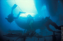
In an underwater habitat, observations can be carried out at any hour to study the behavior of both diurnal and nocturnal organisms. Habitats in shallow water can be used to accommodate divers from greater depths for a major portion of the decompression required. This principle was used in the project Conshelf II. Saturation dives provide the opportunity to dive with shorter intervals than possible from the surface, and risks associated with diving and ship operations at night can be minimized. In the habitat La Chalupa, 35% of all dives took place at night. To perform the same amount of useful work diving from the surface instead of from La Chalupa, an estimated eight hours of decompression time would have been necessary every day.
However, maintaining an underwater habitat is much more expensive and logistically difficult than diving from the surface. It also restricts the diving to a much more limited area.

Technical classification and description

Architectural variations

Underwater Habitat.jpg Floating
The habitat is in the underwater hull of a floating structure. In the Sea Orbiter example this part should reach a depth of 30 metres (98 ft). The advantage of this type is horizontal mobility.
Underwater Habitat Tpe 2.jpg Access shaft to the surface
The habitat is accessible via a shaft to above the water surface. The depth of submersion is quite limited. However, normal atmospheric pressure can be maintained inside so that visitors do not have to undergo any decompression. This type is generally used inshore such as the underwater restaurant Ithaa in the Maldives or Red Sea Star in Eilat, Israel.
Underwater Habitat Type 3.jpg Semi-autonomous
Habitats of this type are accessible only by diving, but energy and breathing gas are supplied by an umbilical cable. Most stations are of this type, such as Aquarius, SEALAB I and II and Helgoland
Underwater Habitat Type 4.jpg Autonomous
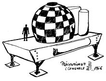
The station has its own reserves of energy and breathing gas and is able to maneuver itself (at least in the vertical direction). This type is similar to submarines or atmospheric diving suits, but it avoids complete environmental separation. Examples of this type include Conshelf III and Bentos-300.

Pressure modes

Underwater habitats are designed to operate in two fundamental modes.

  1. Open to ambient pressure via a moon pool, meaning the air pressure inside the habitat equals underwater pressure at the same level, such as SEALAB. This makes entry and exit easy as there is no physical barrier other than the moon pool water surface. Living in ambient pressure habitats is a form of saturation diving, and return to the surface will require appropriate decompression.
  2. Closed to the sea by hatches, with internal air pressure less than ambient pressure and at or closer to atmospheric pressure; entry or exit to the sea requires passing through hatches and an airlock. Decompression may be necessary when entering the habitat after a dive. This would be done in the airlock.

A third or composite type has compartments of both types within the same habitat structure and connected via airlocks, such as Aquarius.

Components

Habitat
The air filled underwater structure in which the occupants live and work
Life support buoy (LSB)
The floating structure moored to the habitat which provides energy, air, fresh water, telecommunication and telemetry. The connection between Habitat and LSB is made by a multi-core umbilical cable in which all hoses and cables are combined.
Personnel transfer capsule (PTC)
Closed diving bell, a submersible decompression chamber which can be lowered to the habitat to transfer aquanauts back to the surface under pressure, where they can be transferred while still under pressure to a decompression chamber on the support vessel for safer decompression.
Deck decompression chamber (DDC)
A decompression chamber on the support vessel.
Diving support vessel (DSV)
Surface vessel used in support of diving operations
Shore base station
A shore establishment where operations can be monitored. It may include a diving control base, workshops and accommodation.

Excursions

An excursion is a visit to the environment outside the habitat. Diving excursions can be done on scuba or umbilical supply, and are limited upwards by decompression obligations while on the excursion, and downwards by decompression obligations while returning from the excursion.

Open circuit or rebreather scuba have the advantage of mobility, but it is critical to the safety of a saturation diver to be able to get back to the habitat, as surfacing directly from saturation is likely to cause severe and probably fatal decompression sickness. For this reason, in most of the programs, signs and guidelines are installed around the habitat in order to prevent divers from getting lost.

Umbilicals or airline hoses are safer, as the breathing gas supply is unlimited, and the hose is a guideline back to the habitat, but they restrict freedom of movement and can become tangled.

The horizontal extent of excursions is limited to the scuba air supply or the length of the umbilical. The distance above and below the level of the habitat are also limited and depend on the depth of the habitat and the associated saturation of the divers. The open space available for exits thus describes the shape of a vertical axis cylinder centred on the habitat.

As an example, in the Tektite I program, the habitat was located at a depth of 13.1 metres (43 ft). Exits were limited vertically to a depth of 6.7 metres (22 ft) (6.4 m above the habitat) and 25.9 metres (85 ft) (12.8 m below the habitat level) and were horizontally limited to a distance of 549 metres (1,801 ft) from the Habitat.

History

The history of underwater habitats follows on from the previous development of diving bells and caissons, and as long exposure to a hyperbaric environment results in saturation of the body tissues with the ambient inert gases, it is also closely connected to the history of saturation diving. The original inspiration for the development of underwater habitats was the work of George F. Bond, who investigated the physiological and medical effects of hyperbaric saturation in the Genesis project between 1957 and 1963.

Edwin Albert Link started the Man-in-the-Sea project in 1962, which exposed divers to hyperbaric conditions underwater in a diving chamber, culminating in the first aquanaut, Robert Sténuit, spending over 24 hours at a depth of 200 feet (61 m).

Also inspired by Genesis, Jacques-Yves Cousteau conducted the first Conshelf project in France in 1962 where two divers spent a week at a depth of 10 metres (33 ft), followed in 1963 by Conshelf II at 11 metres (36 ft) for a month and 25 metres (82 ft) for two weeks.

In June 1964, Robert Sténuit and Jon Lindberg spent 49 hours at 126m in Link's Man-in-the-Sea II project. The habitat was an inflatable structure called SPID.

This was followed by a series of underwater habitats where people stayed for several weeks at great depths. Sealab II had a usable area of 63 square metres (680 sq ft), and was used at a depth of more than 60 metres (200 ft). Several countries built their own habitats at much the same time and mostly began experimenting in shallow waters. In Conshelf III six aquanauts lived for several weeks at a depth of 100 metres (330 ft). In Germany, the Helgoland UWL was the first habitat to be used in cold water, the Tektite stations were more spacious and technically more advanced. The most ambitious project was Sealab III, a rebuild of Sealab II, which was to be operated at 186 metres (610 ft). When one of the divers died in the preparatory phase due to human error, all similar projects of the United States Navy were terminated. Internationally, except for the La Chalupa Research Laboratory the large-scale projects were carried out, but not extended, so that the subsequent habitats were smaller and designed for shallower depths. The race for greater depths, longer missions and technical advances seemed to have come to an end.

For reasons such as lack of mobility, lack of self-sufficiency, shifting focus to space travel and transition to surface-based saturation systems, the interest in underwater habitats decreased, resulting in a noticeable decrease in major projects after 1970. In the mid eighties, the Aquarius habitat was built in the style of Sealab and Helgoland and is still in operation today.

Historical underwater habitats

Man-in-the-Sea I and II

Man-in-the-Sea I – a minimal habitat

The first aquanaut was Robert Stenuit in the Man-in-the-Sea I project run by Edwin A. Link. On 6 September 1962, he spent 24 hours and 15 minutes at a depth of 61 metres (200 ft) in a steel cylinder, doing several excursions. In June 1964 Stenuit and Jon Lindbergh spent 49 hours at a depth of 126 metres (413 ft) in the Man-in-the-Sea II program. The habitat consisted of a submerged portable inflatable dwelling (SPID).

Conshelf I, II and III

Conshelf II – Starfish
 
Conshelf III

Conshelf, short for Continental Shelf Station, was a series of undersea living and research stations undertaken by Jacques Cousteau's team in the 1960s. The original design was for five of these stations to be submerged to a maximum depth of 300 metres (1,000 ft) over the decade; in reality only three were completed with a maximum depth of 100 metres (330 ft). Much of the work was funded in part by the French petrochemical industry, who, along with Cousteau, hoped that such colonies could serve as base stations for the future exploitation of the sea. Such colonies did not find a productive future, however, as Cousteau later repudiated his support for such exploitation of the sea and put his efforts toward conservation. It was also found in later years that industrial tasks underwater could be more efficiently performed by undersea robot devices and men operating from the surface or from smaller lowered structures, made possible by a more advanced understanding of diving physiology. Still, these three undersea living experiments did much to advance man's knowledge of undersea technology and physiology, and were valuable as "proof of concept" constructs. They also did much to publicize oceanographic research and, ironically, usher in an age of ocean conservation through building public awareness. Along with Sealab and others, it spawned a generation of smaller, less ambitious yet longer-term undersea habitats primarily for marine research purposes.

Conshelf I (Continental Shelf Station), constructed in 1962, was the first inhabited underwater habitat. Developed by Cousteau to record basic observations of life underwater, Conshelf I was submerged in 10 metres (33 ft) of water near Marseille, and the first experiment involved a team of two spending seven days in the habitat. The two oceanauts, Albert Falco and Claude Wesly, were expected to spend at least five hours a day outside the station, and were subject to daily medical exams.

Conshelf Two, the first ambitious attempt for men to live and work on the sea floor, was launched in 1963. In it, a half-dozen oceanauts lived 10 metres (33 ft) down in the Red Sea off Sudan in a starfish-shaped house for 30 days. The undersea living experiment also had two other structures, one a submarine hangar that housed a small, two-man submarine named SP-350 Denise, often referred to as the "diving saucer" for its resemblance to a science fiction flying saucer, and a smaller "deep cabin" where two oceanauts lived at a depth of 30 metres (100 ft) for a week. They were among the first to breathe heliox, a mixture of helium and oxygen, avoiding the normal nitrogen/oxygen mixture, which, when breathed under pressure, can cause narcosis. The deep cabin was also an early effort in saturation diving, in which the aquanauts' body tissues were allowed to become totally saturated by the helium in the breathing mixture, a result of breathing the gases under pressure. The necessary decompression from saturation was accelerated by using oxygen enriched breathing gases. They suffered no apparent ill effects.

The undersea colony was supported with air, water, food, power, all essentials of life, from a large support team above. Men on the bottom performed a number of experiments intended to determine the practicality of working on the sea floor and were subjected to continual medical examinations. Conshelf II was a defining effort in the study of diving physiology and technology, and captured wide public appeal due to its dramatic "Jules Verne" look and feel. A Cousteau-produced feature film about the effort (World Without Sun) was awarded an Academy Award for Best Documentary the following year.

Conshelf III was initiated in 1965. Six divers lived in the habitat at 102.4 metres (336 ft) in the Mediterranean Sea near the Cap Ferrat lighthouse, between Nice and Monaco, for three weeks. In this effort, Cousteau was determined to make the station more self-sufficient, severing most ties with the surface. A mock oil rig was set up underwater, and divers successfully performed several industrial tasks.

SEALAB I, II and III

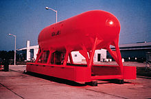
SEALAB I
 
SEALAB II
 
Artist's impression of SEALAB III

SEALAB I, II, and III were experimental underwater habitats developed by the United States Navy in the 1960s to prove the viability of saturation diving and humans living in isolation for extended periods of time. The knowledge gained from the SEALAB expeditions helped advance the science of deep sea diving and rescue, and contributed to the understanding of the psychological and physiological strains humans can endure. The three SEALABs were part of the United States Navy Genesis Project. Preliminary research work was undertaken by George F. Bond. Bond began investigations in 1957 to develop theories about saturation diving. Bond's team exposed rats, goats, monkeys, and human beings to various gas mixtures at different pressures. By 1963 they had collected enough data to test the first SEALAB habitat.

Tektite I and II

Tektite I habitat

The Tektite underwater habitat was constructed by General Electric and was funded by NASA, the Office of Naval Research and the United States Department of the Interior.

On 15 February 1969, four Department of the Interior scientists (Ed Clifton, Conrad Mahnken, Richard Waller and John VanDerwalker) descended to the ocean floor in Great Lameshur Bay in the United States Virgin Islands to begin an ambitious diving project dubbed "Tektite I". By 18 March 1969, the four aquanauts had established a new world's record for saturated diving by a single team. On 15 April 1969, the aquanaut team returned to the surface after performing 58 days of marine scientific studies. More than 19 hours of decompression were needed to safely return the team to the surface.

Inspired in part by NASA's budding Skylab program and an interest in better understanding the effectiveness of scientists working under extremely isolated living conditions, Tektite was the first saturation diving project to employ scientists rather than professional divers.

The term tektite generally refers to a class of meteorites formed by extremely rapid cooling. These include objects of celestial origins that strike the sea surface and come to rest on the bottom (note project Tektite's conceptual origins within the U.S space program).

The Tektite II missions were carried out in 1970. Tektite II comprised ten missions lasting 10 to 20 days with four scientists and an engineer on each mission. One of these missions included the first all-female aquanaut team, led by Dr. Sylvia Earle. Other scientists participating in the all-female mission included Dr. Renate True of Tulane University, as well as Ann Hartline and Alina Szmant, graduate students at Scripps Institute of Oceanography. The fifth member of the crew was Margaret Ann Lucas, a Villanova University engineering graduate, who served as Habitat Engineer. The Tektite II missions were the first to undertake in-depth ecological studies.

Tektite II included 24 hour behavioral and mission observations of each of the missions by a team of observers from the University of Texas at Austin. Selected episodic events and discussions were videotaped using cameras in the public areas of the habitat. Data about the status, location and activities of each of the 5 members of each mission was collected via key punch data cards every six minutes during each mission. This information was collated and processed by BellComm and was used for the support of papers written about the research concerning the relative predictability of behavior patterns of mission participants in constrained, dangerous conditions for extended periods of time, such as those that might be encountered in crewed spaceflight. The Tektite habitat was designed and built by General Electric Space Division at the Valley Forge Space Technology Center in King of Prussia, Pennsylvania. The Project Engineer who was responsible for the design of the habitat was Brooks Tenney, Jr. Tenney also served as the underwater Habitat Engineer on the International Mission, the last mission on the Tektite II project. The Program Manager for the Tektite projects at General Electric was Dr. Theodore Marton.

Hydrolab

Exterior of Hydrolab
 
Inside Hydrolab

Hydrolab was constructed in 1966 and used as a research station from 1970. The project was in part funded by the National Oceanic and Atmospheric Administration (NOAA). Hydrolab could house four people. Approximately 180 Hydrolab missions were conducted—100 missions in The Bahamas during the early to mid-1970s, and 80 missions off Saint Croix, U.S. Virgin Islands, from 1977 to 1985. These scientific missions are chronicled in the Hydrolab Journal. Dr. William Fife spent 28 days in saturation, performing physiology experiments on researchers such as Dr. Sylvia Earle.

The habitat was decommissioned in 1985 and placed on display at the Smithsonian Institution's National Museum of Natural History in Washington, D.C. As of 2017, the habitat is located at the NOAA Auditorium and Science Center at National Oceanic and Atmospheric Administration (NOAA) headquarters in Silver Spring, Maryland.

Edalhab

EDALHAB 01

The Engineering Design and Analysis Laboratory Habitat was a horizontal cylinder 2.6 m high, 3.3 m long and weighing 14 tonnes was built by students of the Engineering Design and Analysis Laboratory in the US. From 26 April 1968, four students spent 48 hours and 6 minutes in this habitat in Alton Bay, New Hampshire. Two further missions followed to 12.2 m.

In the 1972 Edalhab II Florida Aquanaut Research Expedition experiments, the University of New Hampshire and NOAA used nitrox as a breathing gas. In the three FLARE missions, the habitat was positioned off Miami at a depth of 13.7 m. The conversion to this experiment increased the weight of the habitat to 23 tonnes.

BAH I

Underwater laboratory BAH-1 at the Nautineum, Stralsund

BAH I (for Biological Institute Helgoland ) had a length of 6 m and a diameter of 2 m. It weighed about 20 tons and was intended for a crew of two people. The first mission in September 1968 with Jürgen Dorschel and Gerhard Lauckner at 10 m depth in the Baltic Sea lasted 11 days. In June 1969, a one-week flat-water mission took place in Lake Constance. In attempting to anchor the habitat at 47 m, the structure was flooded with the two divers in it and sank to the seabed. It was decided to lift it with the two divers according to the necessary decompression profile and nobody was harmed. BAH I provided valuable experience for the much larger underwater laboratory Helgoland. In 2003 it was taken over as a technical monument by the Technical University of Clausthal-Zellerfeld and in the same year went on display at the Nautineum Stralsund on Kleiner Dänholm island.

Helgoland

The Helgoland underwater laboratory (UWL) at Nautineum, Stralsund (Germany)

The Helgoland underwater laboratory (UWL) is an underwater habitat. It was built in Lübeck, Germany in 1968, and was the first of its kind in the world built for use in colder waters.

The 14 meter long, 7 meter diameter UWL allowed divers to spend several weeks under water using saturation diving techniques. The scientists and technicians would live and work in the laboratory, returning to it after every diving session. At the end of their stay they decompressed in the UWL, and could resurface without decompression sickness.

The UWL was used in the waters of the North and Baltic Seas and, in 1975, on Jeffreys Ledge, in the Gulf of Maine off the coast of New England in the United States. At the end of the 1970s it was decommissioned and in 1998 donated to the German Oceanographic Museum where it can be visited at the Nautineum, a branch of the museum in Stralsund.

Bentos-300

Hulk of soviet experimental submarine "Bentos-300" (project 1603) for underwater biological research

Bentos-300 (Bentos minus 300) was a maneuverable Soviet submersible with a diver lockout facility that could be stationed at the seabed. It was able to spend two weeks underwater at a maximum depth of 300m with about 25 people on board. Although announced in 1966, it had its first deployment in 1977. [1] There were two vessels in the project. After Bentos-300 sank in the Russian Black Sea port of Novorossiisk in 1992, several attempts to recover it failed. In November 2011 it was cut up and recovered for scrap in the following six months.

Progetto Abissi

Progetto Abissi habitat

The Italian Progetto Abissi habitat, also known as La Casa in Fondo al Mare (Italian for The House at the Bottom of the Sea), was designed by the diving team Explorer Team Pellicano, consisted of three cylindrical chambers and served as a platform for a television game show. It was deployed for the first time in September 2005 for ten days, and six aquanauts lived in the complex for 14 days in 2007.

Existing underwater habitats

Aquarius

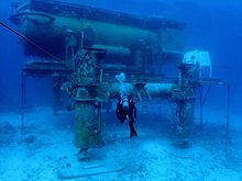
Aquarius underwater laboratory on Conch Reef, off the Florida Keys.
 
Aquarius laboratory underwater
 
Aquarius laboratory on shore

The Aquarius Reef Base is an underwater habitat located 5.4 miles (9 kilometers) off Key Largo in the Florida Keys National Marine Sanctuary. It is deployed on the ocean floor 62 feet (19 m) below the surface and next to a deep coral reef named Conch Reef.

Aquarius is one of three undersea laboratories in the world dedicated to science and education. Two additional undersea facilities, also located in Key Largo, Florida, are owned and operated by Marine Resources Development Foundation. Aquarius was owned by the National Oceanic and Atmospheric Administration (NOAA) and operated by the University of North Carolina–Wilmington until 2013 when Florida International University assumed operational control.

Florida International University (FIU) took ownership of Aquarius in October 2014. As part of the FIU Marine Education and Research Initiative, the Medina Aquarius Program is dedicated to the study and preservation of marine ecosystems worldwide and is enhancing the scope and impact of FIU on research, educational outreach, technology development, and professional training. At the heart of the program is the Aquarius Reef Base.

MarineLab

The MarineLab underwater laboratory is the longest serving seafloor habitat in history, having operated continuously since 1984 under the direction of aquanaut Chris Olstad at Key Largo, Florida. The seafloor laboratory has trained hundreds of individuals in that time, featuring an extensive array of educational and scientific investigations from United States military investigations to pharmaceutical development.

Beginning with a project initiated in 1973, MarineLab, then known as Midshipman Engineered & Designed Undersea Systems Apparatus (MEDUSA), was designed and built as part of an ocean engineering student program at the United States Naval Academy under the direction of Dr. Neil T. Monney. In 1983, MEDUSA was donated to the Marine Resources Development Foundation (MRDF), and in 1984 was deployed on the seafloor in John Pennekamp Coral Reef State Park, Key Largo, Florida. The 2.4-by-4.9-metre (8 by 16 ft) shore-supported habitat supports three or four persons and is divided into a laboratory, a wet-room, and a 1.7-metre-diameter (5 ft 7 in) transparent observation sphere. From the beginning, it has been used by students for observation, research, and instruction. In 1985, it was renamed MarineLab and moved to the 9-metre-deep (30 ft) mangrove lagoon at MRDF headquarters in Key Largo at a depth of 8.3 metres (27 ft) with a hatch depth of 6 m (20 ft). The lagoon contains artifacts and wrecks placed there for education and training. From 1993 to 1995, NASA used MarineLab repeatedly to study Controlled Ecological Life Support Systems (CELLS). These education and research programs qualify MarineLab as the world's most extensively used habitat.

MarineLab was used as an integral part of the "Scott Carpenter, Man in the Sea" Program.

La Chalupa research laboratory

La Chalupa research laboratory, now known as Jules' Undersea Lodge

In the early 1970s, Ian Koblick, president of Marine Resources Development Foundation, developed and operated the La Chalupa research laboratory, which was the largest and most technologically advanced underwater habitat of its time. Koblick, who has continued his work as a pioneer in developing advanced undersea programs for ocean science and education, is the co-author of the book Living and Working in the Sea and is considered one of the foremost authorities on undersea habitation.

La Chalupa was operated off Puerto Rico. During the habitat's launching for its second mission, a steel cable wrapped around Dr. Lance Rennka's left wrist, shattering his arm, which he subsequently lost to gas gangrene.

In the mid-1980s La Chalupa was transformed into Jules' Undersea Lodge in Key Largo, Florida. Jules' co-developer, Dr. Neil Monney, formerly served as Professor and Director of Ocean Engineering at the U.S. Naval Academy, and has extensive experience as a research scientist, aquanaut and designer of underwater habitats.

La Chalupa was used as the primary platform for the Scott Carpenter Man in the Sea Program, an underwater analog to Space Camp. Unlike Space Camp, which utilizes simulations, participants performed scientific tasks while using actual saturation diving systems. This program, envisioned by Ian Koblick and Scott Carpenter, was directed by Phillip Sharkey with operational help of Chris Olstad. Also used in the program was the MarineLab Underwater Habitat, the submersible Sea Urchin (designed and built by Phil Nuytten), and an Oceaneering Saturation Diving system consisting of an on-deck decompression chamber and a diving bell. La Chalupa was the site of the first underwater computer chat, a session hosted on GEnie's Scuba RoundTable (the first non-computing related area on GEnie) by then-director Sharkey from inside the habitat. Divers from all over the world were able to direct questions to him and to Commander Carpenter.

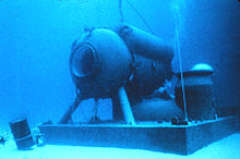
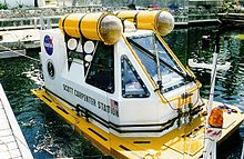
Scott Carpenter Space Analog Station

Scott Carpenter Space Analog Station

The Scott Carpenter Space Analog Station was launched near Key Largo on six-week missions in 1997 and 1998. The station was a NASA project illustrating the analogous science and engineering concepts common to both undersea and space missions. During the missions, some 20 aquanauts rotated through the undersea station including NASA scientists, engineers and director James Cameron. The SCSAS was designed by NASA engineer Dennis Chamberland.

Lloyd Godson's Biosub

Lloyd Godson's Biosub was an underwater habitat, built in 2007 for a competition by Australian Geographic. The Biosub generated its own electricity (using a bike); its own water, using the Air2Water Dragon Fly M18 system; and its own air, using algae that produce O2. The algae were fed using the Cascade High School Advanced Biology Class Biocoil. The habitat shelf itself was constructed by Trygons Designs.

Galathée

Galathée Underwater Laboratory and Habitat – 1977

The first underwater habitat built by Jacques Rougerie was launched and immersed on 4 August 1977. The unique feature of this semi-mobile habitat-laboratory is that it can be moored at any depth between 9 and 60 metres, which gives it the capability of phased integration in the marine environment. This habitat therefore has a limited impact on the marine ecosystem and is easy to position. Galathée was experienced by Jacques Rougerie himself.

Aquabulle

Aquabulle, Underwater Laboratory – 1978

Launched for the first time in March 1978, this underwater shelter suspended in midwater (between 0 and 60 metres) is a mini scientific observatory 2.8 metres high by 2.5 metres in diameter. The Aquabulle, created and experienced by Jacques Rougerie, can accommodate three people for a period of several hours and acts as an underwater refuge. A series of Aquabulles were later built and some are still being used by laboratories.

Hippocampe

Hippocampe, Underwater Habitat – 1981

This underwater habitat, created by a French architect, Jacques Rougerie, was launched in 1981 to act as a scientific base suspended in midwater using the same method as Galathée. Hippocampe can accommodate 2 people on saturation dives up to a depth of 12 metres for periods of 7 to 15 days, and was also designed to act as a subsea logistics base for the offshore industry. 

Ithaa undersea restaurant

Interior of the Ithaa restaurant

Ithaa (Dhivehi for mother of pearl) is the world's only fully glazed underwater restaurant and is located in the Conrad Maldives Rangali Island hotel. It is accessible via a corridor from above the water and is open to the atmosphere, so there is no need for compression or decompression procedures. Ithaa was built by M.J. Murphy Ltd, and has an unballasted mass of 175 tonnes.

Red Sea Star

Red Sea Star in Eilat

The "Red Sea Star" restaurant in Eilat, Israel, consisted of three modules; an entrance area above the water surface, a restaurant with 62 panorama windows 6 m under water and a ballast area below. The entire construction weighs about 6000 tons. The restaurant had a capacity of 105 people. It shut down in 2012.

Eilat’s Coral World Underwater Observatory

Underwater observatory in Eilat, Israel.

The first part of Eilat's Coral World Underwater Observatory was built in 1975 and it was expanded in 1991 by adding a second underwater observatory connected by a tunnel. The underwater complex is accessible via a footbridge from the shore and a shaft from above the water surface. The observation area is at a depth of approximately 12 m.

Conceptual underwater habitats

Sub-Biosphere 2

A concept design by internationally recognized conceptual designer and futurist Phil Pauley. The Sub-Biosphere 2 is the original self-sustaining underwater habitat designed for aquanauts, tourism and oceanographic life sciences and longterm human, plant and animal habitation. SBS2 is a seed bank with eight Living Biomes to allow human, plant and fresh water interaction, powered and controlled by the Central Support Biome which monitors the life systems from within its own operations facility.

Inequality (mathematics)

From Wikipedia, the free encyclopedia https://en.wikipedia.org/wiki/Inequality...