Energy harvesting (EH, also known as power harvesting or energy scavenging or ambient power) is the process by which energy is derived from external sources (e.g., solar power, thermal energy, wind energy, salinity gradients, and kinetic energy, also known as ambient energy), captured, and stored for small, wireless autonomous devices, like those used in wearable electronics and wireless sensor networks.
Energy harvesters usually provide a very small amount of power for low-energy electronics. While the input fuel to some large-scale generation costs resources (oil, coal, etc.), the energy source for energy harvesters is present as ambient background. For example, temperature gradients exist from the operation of a combustion engine and in urban areas, there is a large amount of electromagnetic energy in the environment because of radio and television broadcasting.
One of the earliest applications of ambient power collected from ambient electromagnetic radiation (EMR) is the crystal radio.
The principles of energy harvesting from ambient EMR can be demonstrated with basic components.
Operation
Energy harvesting devices converting ambient energy into electrical energy have attracted much interest in both the military and commercial sectors. Some systems convert motion, such as that of ocean waves, into electricity to be used by oceanographic monitoring sensors for autonomous operation. Future applications may include high power output devices (or arrays of such devices) deployed at remote locations to serve as reliable power stations for large systems. Another application is in wearable electronics, where energy harvesting devices can power or recharge cellphones, mobile computers, radio communication equipment, etc. All of these devices must be sufficiently robust to endure long-term exposure to hostile environments and have a broad range of dynamic sensitivity to exploit the entire spectrum of wave motions.
Accumulating energy
Energy can also be harvested to power small autonomous sensors such as those developed using MEMS technology. These systems are often very small and require little power, but their applications are limited by the reliance on battery power. Scavenging energy from ambient vibrations, wind, heat or light could enable smart sensors to be functional indefinitely.
Typical power densities available from energy harvesting devices are highly dependent upon the specific application (affecting the generator's size) and the design itself of the harvesting generator. In general, for motion powered devices, typical values are a few μW/cm3 for human body powered applications and hundreds of μW/cm3 for generators powered from machinery. Most energy scavenging devices for wearable electronics generate very little power.
Storage of power
In general, energy can be stored in a capacitor, super capacitor, or battery. Capacitors are used when the application needs to provide huge energy spikes. Batteries leak less energy and are therefore used when the device needs to provide a steady flow of energy. these aspects of the battery depend on the type that is used. A common type of battery that is used for this purpose is the lead acid or lithium ion battery although older types such as nickel metal hydride are still widely used today. Compared to batteries, super capacitors have virtually unlimited charge-discharge cycles and can therefore operate forever enabling a maintenance-free operation in IoT and wireless sensor devices.
Use of the power
Current interest in low power energy harvesting is for independent sensor networks. In these applications an energy harvesting scheme puts power stored into a capacitor then boosted/regulated to a second storage capacitor or battery for the use in the microprocessor or in the data transmission. The power is usually used in a sensor application and the data stored or is transmitted possibly through a wireless method.
Motivation
The history of energy harvesting dates back to the windmill and the waterwheel. People have searched for ways to store the energy from heat and vibrations for many decades. One driving force behind the search for new energy harvesting devices is the desire to power sensor networks and mobile devices without batteries. Energy harvesting is also motivated by a desire to address the issue of climate change and global warming.
Energy sources
There are many small-scale energy sources that generally cannot be scaled up to industrial size in terms of comparable output to industrial size solar, wind or wave power:
- Some wristwatches are powered by kinetic energy (called automatic watches), in this case movement of the arm is used. The arm movement causes winding of its mainspring. A newer design introduced by Seiko ("Kinetic") uses movement of a magnet in the electromagnetic generator instead to power the quartz movement. The motion provides a rate of change of flux, which results in some induced emf on the coils. The concept is related to Faraday's Law.
- Photovoltaics is a method of generating electrical power by converting solar radiation (both indoors and outdoors) into direct current electricity using semiconductors that exhibit the photovoltaic effect. Photovoltaic power generation employs solar panels composed of a number of cells containing a photovoltaic material. Note that photovoltaics have been scaled up to industrial size and that large solar farms exist.
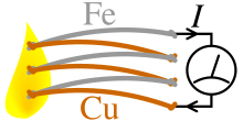
- Thermoelectric generators (TEGs) consist of the junction of two dissimilar materials and the presence of a thermal gradient. Large voltage outputs are possible by connecting many junctions electrically in series and thermally in parallel. Typical performance is 100–300 μV/K per junction. These can be utilized to capture mW.s of energy from industrial equipment, structures, and even the human body. They are typically coupled with heat sinks to improve temperature gradient.
- Micro wind turbine are used to harvest wind energy readily available in the environment in the form of kinetic energy to power the low power electronic devices such as wireless sensor nodes. When air flows across the blades of the turbine, a net pressure difference is developed between the wind speeds above and below the blades. This will result in a lift force generated which in turn rotate the blades. Similar to photovoltaics, wind farms have been constructed on an industrial scale and are being used to generate substantial amounts of electrical energy.
- Piezoelectric crystals or fibers generate a small voltage whenever they are mechanically deformed. Vibration from engines can stimulate piezoelectric materials, as can the heel of a shoe, or the pushing of a button.
- Special antennas can collect energy from stray radio waves, this can also be done with a Rectenna and theoretically at even higher frequency EM radiation with a Nantenna.
- Power from keys pressed during use of a portable electronic device or remote controller, using magnet and coil or piezoelectric energy converters, may be used to help power the device.
- Vibration energy harvesting based on Electromagnetic induction that uses a magnet and a copper coil in the most simple versions to generate a current that can be converted into electricity.
Ambient-radiation sources
A possible source of energy comes from ubiquitous radio transmitters. Historically, either a large collection area or close proximity to the radiating wireless energy source is needed to get useful power levels from this source. The nantenna is one proposed development which would overcome this limitation by making use of the abundant natural radiation (such as solar radiation).
One idea is to deliberately broadcast RF energy to power and collect information from remote devices: This is now commonplace in passive radio-frequency identification (RFID) systems, but the Safety and US Federal Communications Commission (and equivalent bodies worldwide) limit the maximum power that can be transmitted this way to civilian use. This method has been used to power individual nodes in a wireless sensor network.
Fluid flow
Airflow can be harvested by various turbine and non-turbine generator technologies. Towered wind turbines and airborne wind energy systems (AWES) mine the flow of air. There are multiple companies in this space, with one example being Zephyr Energy Corporation's patented Windbeam micro generator captures energy from airflow to recharge batteries and power electronic devices. The Windbeam's novel design allows it to operate silently in wind speeds as low as 2 mph. The generator consists of a lightweight beam suspended by durable long-lasting springs within an outer frame. The beam oscillates rapidly when exposed to airflow due to the effects of multiple fluid flow phenomena. A linear alternator assembly converts the oscillating beam motion into usable electrical energy. A lack of bearings and gears eliminates frictional inefficiencies and noise. The generator can operate in low-light environments unsuitable for solar panels (e.g. HVAC ducts) and is inexpensive due to low cost components and simple construction. The scalable technology can be optimized to satisfy the energy requirements and design constraints of a given application.
The flow of blood can also be used to power devices. For instance, the pacemaker developed at the University of Bern, uses blood flow to wind up a spring which in turn drives an electrical micro-generator.
Water energy harvesting with high energy conversion efficiency and high power density was achieved by the design of generators with transistor-like architecture.
Photovoltaic
Photovoltaic (PV) energy harvesting wireless technology offers significant advantages over wired or solely battery-powered sensor solutions: virtually inexhaustible sources of power with little or no adverse environmental effects. Indoor PV harvesting solutions have to date been powered by specially tuned amorphous silicon (aSi)a technology most used in Solar Calculators. In recent years new PV technologies have come to the forefront in Energy Harvesting such as Dye-Sensitized Solar Cells (DSSC). The dyes absorb light much like chlorophyll does in plants. Electrons released on impact escape to the layer of TiO2 and from there diffuse, through the electrolyte, as the dye can be tuned to the visible spectrum much higher power can be produced. At 200 lux a DSSC can provide over 10 μW per cm2.
Piezoelectric
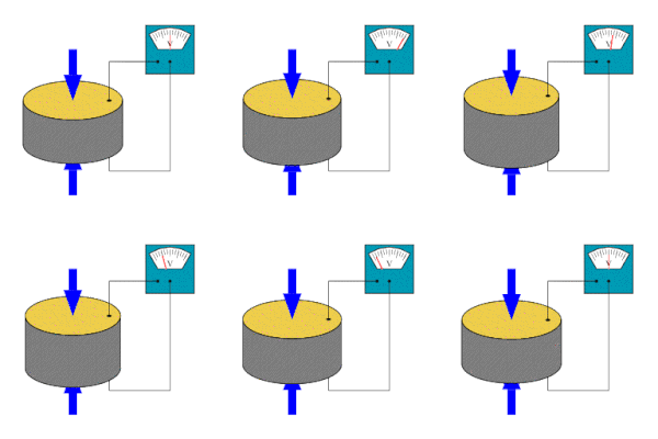
The piezoelectric effect converts mechanical strain into electric current or voltage. This strain can come from many different sources. Human motion, low-frequency seismic vibrations, and acoustic noise are everyday examples. Except in rare instances the piezoelectric effect operates in AC requiring time-varying inputs at mechanical resonance to be efficient.
Most piezoelectric electricity sources produce power on the order of milliwatts, too small for system application, but enough for hand-held devices such as some commercially available self-winding wristwatches. One proposal is that they are used for micro-scale devices, such as in a device harvesting micro-hydraulic energy. In this device, the flow of pressurized hydraulic fluid drives a reciprocating piston supported by three piezoelectric elements which convert the pressure fluctuations into an alternating current.
As piezo energy harvesting has been investigated only since the late 1990s, it remains an emerging technology. Nevertheless, some interesting improvements were made with the self-powered electronic switch at INSA school of engineering, implemented by the spin-off Arveni. In 2006, the proof of concept of a battery-less wireless doorbell push button was created, and recently, a product showed that classical wireless wallswitch can be powered by a piezo harvester. Other industrial applications appeared between 2000 and 2005, to harvest energy from vibration and supply sensors for example, or to harvest energy from shock.
Piezoelectric systems can convert motion from the human body into electrical power. DARPA has funded efforts to harness energy from leg and arm motion, shoe impacts, and blood pressure for low level power to implantable or wearable sensors. The nanobrushes are another example of a piezoelectric energy harvester. They can be integrated into clothing. Multiple other nanostructures have been exploited to build an energy-harvesting device, for example, a single crystal PMN-PT nanobelt was fabricated and assembled into a piezoelectric energy harvester in 2016. Careful design is needed to minimise user discomfort. These energy harvesting sources by association affect the body. The Vibration Energy Scavenging Project is another project that is set up to try to scavenge electrical energy from environmental vibrations and movements. Microbelt can be used to gather electricity from respiration. Besides, as the vibration of motion from human comes in three directions, a single piezoelectric cantilever based omni-directional energy harvester is created by using 1:2 internal resonance. Finally, a millimeter-scale piezoelectric energy harvester has also already been created.
Piezo elements are being embedded in walkways to recover the "people energy" of footsteps. They can also be embedded in shoes to recover "walking energy". Researchers at MIT developed the first micro-scale piezoelectric energy harvester using thin film PZT in 2005. Arman Hajati and Sang-Gook Kim invented the Ultra Wide-Bandwidth micro-scale piezoelectric energy harvesting device by exploiting the nonlinear stiffness of a doubly clamped microelectromechanical systems (MEMSs) resonator. The stretching strain in a doubly clamped beam shows a nonlinear stiffness, which provides a passive feedback and results in amplitude-stiffened Duffing mode resonance. Typically, piezoelectric cantilevers are adopted for the above-mentioned energy harvesting system. One drawback is that the piezoelectric cantilever has gradient strain distribution, i.e., the piezoelectric transducer is not fully utilized. To address this issue, triangle shaped and L-shaped cantilever are proposed for uniform strain distribution.
In 2018, Soochow University researchers reported hybridizing a triboelectric nanogenerator and a silicon solar cell by sharing a mutual electrode. This device can collect solar energy or convert the mechanical energy of falling raindrops into electricity.
UK telecom company Orange UK created an energy harvesting T-shirt and boots. Other companies have also done the same.
Energy from smart roads and piezoelectricity
Brothers Pierre Curie and Jacques Curie gave the concept of piezoelectric effect in 1880. Piezoelectric effect converts mechanical strain into voltage or electric current and generates electric energy from motion, weight, vibration and temperature changes as shown in the figure.
Considering piezoelectric effect in thin film lead zirconate titanate PZT, microelectromechanical systems (MEMS) power generating device has been developed. During recent improvement in piezoelectric technology, Aqsa Abbasi diffentiated two modes called and in vibration converters and re-designed to resonate at specific frequencies from an external vibration energy source, thereby creating electrical energy via the piezoelectric effect using electromechanical damped mass. However, Aqsa further developed beam-structured electrostatic devices that are more difficult to fabricate than PZT MEMS devices versus a similar because general silicon processing involves many more mask steps that do not require PZT film. Piezoelectric type sensors and actuators have a cantilever beam structure that consists of a membrane bottom electrode, film, piezoelectric film, and top electrode. More than (3~5 masks) mask steps are required for patterning of each layer while have very low induced voltage. Pyroelectric crystals that have a unique polar axis and have spontaneous polarization, along which the spontaneous polarization exists. These are the crystals of classes 6mm, 4mm, mm2, 6, 4, 3m, 3,2, m. The special polar axis—crystallophysical axis X3 – coincides with the axes L6,L4, L3, and L2 of the crystals or lies in the unique straight plane P (class "m"). Consequently, the electric centers of positive and negative charges are displaced of an elementary cell from equilibrium positions, i.e., the spontaneous polarization of the crystal changes. Therefore, all considered crystals have spontaneous polarization . Since piezoelectric effect in pyroelectric crystals arises as a result of changes in their spontaneous polarization under external effects (electric fields, mechanical stresses). As a result of displacement, Aqsa Abbasi introduced change in the components along all three axes . Suppose that is proportional to the mechanical stresses causing in a first approximation, which results where Tkl represents the mechanical stress and dikl represents the piezoelectric modules.
PZT thin films have attracted attention for applications such as force sensors, accelerometers, gyroscopes actuators, tunable optics, micro pumps, ferroelectric RAM, display systems and smart roads, when energy sources are limited, energy harvesting plays an important role in the environment. Smart roads have the potential to play an important role in power generation. Embedding piezoelectric material in the road can convert pressure exerted by moving vehicles into voltage and current.
Smart transportation intelligent system
Piezoelectric sensors are most useful in smart-road technologies that can be used to create systems that are intelligent and improve productivity in the long run. Imagine highways that alert motorists of a traffic jam before it forms. Or bridges that report when they are at risk of collapse, or an electric grid that fixes itself when blackouts hit. For many decades, scientists and experts have argued that the best way to fight congestion is intelligent transportation systems, such as roadside sensors to measure traffic and synchronized traffic lights to control the flow of vehicles. But the spread of these technologies has been limited by cost. There are also some other smart-technology shovel ready projects which could be deployed fairly quickly, but most of the technologies are still at the development stage and might not be practically available for five years or more.
Pyroelectric
The pyroelectric effect converts a temperature change into electric current or voltage. It is analogous to the piezoelectric effect, which is another type of ferroelectric behavior. Pyroelectricity requires time-varying inputs and suffers from small power outputs in energy harvesting applications due to its low operating frequencies. However, one key advantage of pyroelectrics over thermoelectrics is that many pyroelectric materials are stable up to 1200 °C or higher, enabling energy harvesting from high temperature sources and thus increasing thermodynamic efficiency.
One way to directly convert waste heat into electricity is by executing the Olsen cycle on pyroelectric materials. The Olsen cycle consists of two isothermal and two isoelectric field processes in the electric displacement-electric field (D-E) diagram. The principle of the Olsen cycle is to charge a capacitor via cooling under low electric field and to discharge it under heating at higher electric field. Several pyroelectric converters have been developed to implement the Olsen cycle using conduction, convection, or radiation. It has also been established theoretically that pyroelectric conversion based on heat regeneration using an oscillating working fluid and the Olsen cycle can reach Carnot efficiency between a hot and a cold thermal reservoir. Moreover, recent studies have established polyvinylidene fluoride trifluoroethylene [P(VDF-TrFE)] polymers and lead lanthanum zirconate titanate (PLZT) ceramics as promising pyroelectric materials to use in energy converters due to their large energy densities generated at low temperatures. Additionally, a pyroelectric scavenging device that does not require time-varying inputs was recently introduced. The energy-harvesting device uses the edge-depolarizing electric field of a heated pyroelectric to convert heat energy into mechanical energy instead of drawing electric current off two plates attached to the crystal-faces.
Thermoelectrics
In 1821, Thomas Johann Seebeck discovered that a thermal gradient formed between two dissimilar conductors produces a voltage. At the heart of the thermoelectric effect is the fact that a temperature gradient in a conducting material results in heat flow; this results in the diffusion of charge carriers. The flow of charge carriers between the hot and cold regions in turn creates a voltage difference. In 1834, Jean Charles Athanase Peltier discovered that running an electric current through the junction of two dissimilar conductors could, depending on the direction of the current, cause it to act as a heater or cooler. The heat absorbed or produced is proportional to the current, and the proportionality constant is known as the Peltier coefficient. Today, due to knowledge of the Seebeck and Peltier effects, thermoelectric materials can be used as heaters, coolers and generators (TEGs).
Ideal thermoelectric materials have a high Seebeck coefficient, high electrical conductivity, and low thermal conductivity. Low thermal conductivity is necessary to maintain a high thermal gradient at the junction. Standard thermoelectric modules manufactured today consist of P- and N-doped bismuth-telluride semiconductors sandwiched between two metallized ceramic plates. The ceramic plates add rigidity and electrical insulation to the system. The semiconductors are connected electrically in series and thermally in parallel.
Miniature thermocouples have been developed that convert body heat into electricity and generate 40 μ W at 3 V with a 5-degree temperature gradient, while on the other end of the scale, large thermocouples are used in nuclear RTG batteries.
Practical examples are the finger-heartratemeter by the Holst Centre and the thermogenerators by the Fraunhofer-Gesellschaft.
Advantages to thermoelectrics:
- No moving parts allow continuous operation for many years.
- Thermoelectrics contain no materials that must be replenished.
- Heating and cooling can be reversed.
One downside to thermoelectric energy conversion is low efficiency (currently less than 10%). The development of materials that are able to operate in higher temperature gradients, and that can conduct electricity well without also conducting heat (something that was until recently thought impossible), will result in increased efficiency.
Future work in thermoelectrics could be to convert wasted heat, such as in automobile engine combustion, into electricity.
Electrostatic (capacitive)
This type of harvesting is based on the changing capacitance of vibration-dependent capacitors. Vibrations separate the plates of a charged variable capacitor, and mechanical energy is converted into electrical energy. Electrostatic energy harvesters need a polarization source to work and to convert mechanical energy from vibrations into electricity. The polarization source should be in the order of some hundreds of volts; this greatly complicates the power management circuit. Another solution consists in using electrets, that are electrically charged dielectrics able to keep the polarization on the capacitor for years. It's possible to adapt structures from classical electrostatic induction generators, which also extract energy from variable capacitances, for this purpose. The resulting devices are self-biasing, and can directly charge batteries, or can produce exponentially growing voltages on storage capacitors, from which energy can be periodically extracted by DC/DC converters.
Magnetic induction
Magnetic induction refers to the production of an electromotive force (i.e., voltage) in a changing magnetic field. This changing magnetic field can be created by motion, either rotation (i.e. Wiegand effect and Wiegand sensors) or linear movement (i.e. vibration).
Magnets wobbling on a cantilever are sensitive to even small vibrations and generate microcurrents by moving relative to conductors due to Faraday's law of induction. By developing a miniature device of this kind in 2007, a team from the University of Southampton made possible the planting of such a device in environments that preclude having any electrical connection to the outside world. Sensors in inaccessible places can now generate their own power and transmit data to outside receivers.
One of the major limitations of the magnetic vibration energy harvester developed at University of Southampton is the size of the generator, in this case approximately one cubic centimeter, which is much too large to integrate into today's mobile technologies. The complete generator including circuitry is a massive 4 cm by 4 cm by 1 cm nearly the same size as some mobile devices such as the iPod nano. Further reductions in the dimensions are possible through the integration of new and more flexible materials as the cantilever beam component. In 2012, a group at Northwestern University developed a vibration-powered generator out of polymer in the form of a spring. This device was able to target the same frequencies as the University of Southampton groups silicon based device but with one third the size of the beam component.
A new approach to magnetic induction based energy harvesting has also been proposed by using ferrofluids. The journal article, "Electromagnetic ferrofluid-based energy harvester", discusses the use of ferrofluids to harvest low frequency vibrational energy at 2.2 Hz with a power output of ~80 mW per g.
Quite recently, the change in domain wall pattern with the application of stress has been proposed as a method to harvest energy using magnetic induction. In this study, the authors have shown that the applied stress can change the domain pattern in microwires. Ambient vibrations can cause stress in microwires, which can induce a change in domain pattern and hence change the induction. Power, of the order of uW/cm2 has been reported.
Commercially successful vibration energy harvesters based on magnetic induction are still relatively few in number. Examples include products developed by Swedish company ReVibe Energy, a technology spin-out from Saab Group. Another example is the products developed from the early University of Southampton prototypes by Perpetuum. These have to be sufficiently large to generate the power required by wireless sensor nodes (WSN) but in M2M applications this is not normally an issue. These harvesters are now being supplied in large volumes to power WSNs made by companies such as GE and Emerson and also for train bearing monitoring systems made by Perpetuum. Overhead powerline sensors can use magnetic induction to harvest energy directly from the conductor they are monitoring.
Blood sugar
Another way of energy harvesting is through the oxidation of blood sugars. These energy harvesters are called biobatteries. They could be used to power implanted electronic devices (e.g., pacemakers, implanted biosensors for diabetics, implanted active RFID devices, etc.). At present, the Minteer Group of Saint Louis University has created enzymes that could be used to generate power from blood sugars. However, the enzymes would still need to be replaced after a few years. In 2012, a pacemaker was powered by implantable biofuel cells at Clarkson University under the leadership of Dr. Evgeny Katz.
Tree-based
Tree metabolic energy harvesting is a type of bio-energy harvesting. Voltree has developed a method for harvesting energy from trees. These energy harvesters are being used to power remote sensors and mesh networks as the basis for a long term deployment system to monitor forest fires and weather in the forest. According to Voltree's website, the useful life of such a device should be limited only by the lifetime of the tree to which it is attached. A small test network was recently deployed in a US National Park forest.
Other sources of energy from trees include capturing the physical movement of the tree in a generator. Theoretical analysis of this source of energy shows some promise in powering small electronic devices. A practical device based on this theory has been built and successfully powered a sensor node for a year.
Metamaterial
A metamaterial-based device wirelessly converts a 900 MHz microwave signal to 7.3 volts of direct current (greater than that of a USB device). The device can be tuned to harvest other signals including Wi-Fi signals, satellite signals, or even sound signals. The experimental device used a series of five fiberglass and copper conductors. Conversion efficiency reached 37 percent. When traditional antennas are close to each other in space they interfere with each other. But since RF power goes down by the cube of the distance, the amount of power is very very small. While the claim of 7.3 volts is grand, the measurement is for an open circuit. Since the power is so low, there can be almost no current when any load is attached.
Atmospheric pressure changes
The pressure of the atmosphere changes naturally over time from temperature changes and weather patterns. Devices with a sealed chamber can use these pressure differences to extract energy. This has been used to provide power for mechanical clocks such as the Atmos clock.
Ocean energy
A relatively new concept of generating energy is to generate energy from oceans. Large masses of waters are present on the planet which carry with them great amounts of energy. The energy in this case can be generated by tidal streams, ocean waves, difference in salinity and also difference in temperature. As of 2018, efforts are underway to harvest energy this way. United States Navy recently was able to generate electricity using difference in temperatures present in the ocean.
One method to use the temperature difference across different levels of the thermocline in the ocean is by using a thermal energy harvester that is equipped with a material that changes phase while in different temperatures regions. This is typically a polymer-based material that can handle reversible heat treatments. When the material is changing phase, the energy differential is converted into mechanical energy. The materials used will need to be able to alter phases, from liquid to solid, depending on the position of the thermocline underwater. These phase change materials within thermal energy harvesting units would be an ideal way to recharge or power an unmanned underwater vehicle (UUV) being that it will rely on the warm and cold water already present in large bodies of water; minimizing the need for standard battery recharging. Capturing this energy would allow for longer-term missions since the need to be collected or return for charging can be eliminated. This is also a very environmentally friendly method of powering underwater vehicles. There are no emissions that come from utilizing a phase change fluid, and it will likely have a longer lifespan than that of a standard battery.
Future directions
Electroactive polymers (EAPs) have been proposed for harvesting energy. These polymers have a large strain, elastic energy density, and high energy conversion efficiency. The total weight of systems based on EAPs (electroactive polymers) is proposed to be significantly lower than those based on piezoelectric materials.
Nanogenerators, such as the one made by Georgia Tech, could provide a new way for powering devices without batteries. As of 2008, it only generates some dozen nanowatts, which is too low for any practical application.
Noise has been the subject of a proposal by NiPS Laboratory in Italy to harvest wide spectrum low scale vibrations via a nonlinear dynamical mechanism that can improve harvester efficiency up to a factor 4 compared to traditional linear harvesters.
Combinations of different types of energy harvesters can further reduce dependence on batteries, particularly in environments where the available ambient energy types change periodically. This type of complementary balanced energy harvesting has the potential to increase reliability of wireless sensor systems for structural health monitoring.











![Clear Skies at Cerro Pachón [125]](https://upload.wikimedia.org/wikipedia/commons/thumb/9/96/Clear_Skies_at_Cerro_Pach%C3%B3n.jpg/400px-Clear_Skies_at_Cerro_Pach%C3%B3n.jpg)
![Vera C. Rubin Observatory under construction [126]](https://upload.wikimedia.org/wikipedia/commons/thumb/9/9d/Vera_C._Rubin_Observatory_under_construction.jpg/400px-Vera_C._Rubin_Observatory_under_construction.jpg)
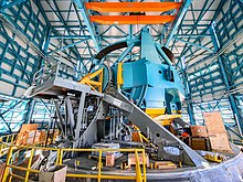
![Telescope mount assembly, taken from the dome during bridge crane installation. [127]](https://upload.wikimedia.org/wikipedia/commons/thumb/e/ef/Rubin_Telescope_Mount_Assembly.jpg/412px-Rubin_Telescope_Mount_Assembly.jpg)
![Focal plane of the LSST Cam. It is 60 cm (2 feet) wide, has 189 sensors to produce 3200-megapixel images. [128]](https://upload.wikimedia.org/wikipedia/commons/thumb/3/37/LSST_Camera_focal_plane.jpg/489px-LSST_Camera_focal_plane.jpg)
![Optical engineers Justin Wolfe (left) and Simon Cohen with the r filter for the LSST Cam. [129]](https://upload.wikimedia.org/wikipedia/commons/thumb/e/e3/Rubin_r-band_Filter_at_Lawrence_Livermore_National_Laboratory.jpg/450px-Rubin_r-band_Filter_at_Lawrence_Livermore_National_Laboratory.jpg)
![The LSST Cam chilled to subzero temperatures using both cooling systems [130]](https://upload.wikimedia.org/wikipedia/commons/thumb/a/a2/LSST_Camera_Lift.jpg/244px-LSST_Camera_Lift.jpg)
