Search This Blog

Saturday, August 20, 2022

Ozone layer

From Wikipedia, the free encyclopedia
 
Ozone-oxygen cycle in the ozone layer.

The ozone layer or ozone shield is a region of Earth's stratosphere that absorbs most of the Sun's ultraviolet radiation. It contains a high concentration of ozone (O3) in relation to other parts of the atmosphere, although still small in relation to other gases in the stratosphere. The ozone layer contains less than 10 parts per million of ozone, while the average ozone concentration in Earth's atmosphere as a whole is about 0.3 parts per million. The ozone layer is mainly found in the lower portion of the stratosphere, from approximately 15 to 35 kilometers (9 to 22 mi) above Earth, although its thickness varies seasonally and geographically.

The ozone layer was discovered in 1913 by the French physicists Charles Fabry and Henri Buisson. Measurements of the sun showed that the radiation sent out from its surface and reaching the ground on Earth is usually consistent with the spectrum of a black body with a temperature in the range of 5,500–6,000 K (5,230–5,730 °C), except that there was no radiation below a wavelength of about 310 nm at the ultraviolet end of the spectrum. It was deduced that the missing radiation was being absorbed by something in the atmosphere. Eventually the spectrum of the missing radiation was matched to only one known chemical, ozone. Its properties were explored in detail by the British meteorologist G. M. B. Dobson, who developed a simple spectrophotometer (the Dobsonmeter) that could be used to measure stratospheric ozone from the ground. Between 1928 and 1958, Dobson established a worldwide network of ozone monitoring stations, which continue to operate to this day. The "Dobson unit", a convenient measure of the amount of ozone overhead, is named in his honor.

The ozone layer absorbs 97 to 99 percent of the Sun's medium-frequency ultraviolet light (from about 200 nm to 315 nm wavelength), which otherwise would potentially damage exposed life forms near the surface.

In 1976, atmospheric research revealed that the ozone layer was being depleted by chemicals released by industry, mainly chlorofluorocarbons (CFCs). Concerns that increased UV radiation due to ozone depletion threatened life on Earth, including increased skin cancer in humans and other ecological problems, led to bans on the chemicals, and the latest evidence is that ozone depletion has slowed or stopped. The United Nations General Assembly has designated September 16 as the International Day for the Preservation of the Ozone Layer.

Venus also has a thin ozone layer at an altitude of 100 kilometers above the planet's surface.

Sources

The photochemical mechanisms that give rise to the ozone layer were discovered by the British physicist Sydney Chapman in 1930. Ozone in the Earth's stratosphere is created by ultraviolet light striking ordinary oxygen molecules containing two oxygen atoms (O2), splitting them into individual oxygen atoms (atomic oxygen); the atomic oxygen then combines with unbroken O2 to create ozone, O3. The ozone molecule is unstable (although, in the stratosphere, long-lived) and when ultraviolet light hits ozone it splits into a molecule of O2 and an individual atom of oxygen, a continuing process called the ozone-oxygen cycle. Chemically, this can be described as:

About 90 percent of the ozone in the atmosphere is contained in the stratosphere. Ozone concentrations are greatest between about 20 and 40 kilometres (66,000 and 131,000 ft), where they range from about 2 to 8 parts per million. If all of the ozone were compressed to the pressure of the air at sea level, it would be only 3 millimetres (18 inch) thick.

Ultraviolet light

UV-B energy levels at several altitudes. Blue line shows DNA sensitivity. Red line shows surface energy level with 10 percent decrease in ozone
 
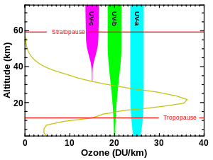
Levels of ozone at various altitudes and blocking of different bands of ultraviolet radiation. Essentially all UV-C (100–280 nm) is blocked by dioxygen (from 100–200 nm) or else by ozone (200–280 nm) in the atmosphere. The shorter portion of the UV-C band and the more energetic UV above this band causes the formation of the ozone layer, when single oxygen atoms produced by UV photolysis of dioxygen (below 240 nm) react with more dioxygen. The ozone layer also blocks most, but not quite all, of the sunburn-producing UV-B (280–315 nm) band, which lies in the wavelengths longer than UV-C. The band of UV closest to visible light, UV-A (315–400 nm), is hardly affected by ozone, and most of it reaches the ground. UV-A does not primarily cause skin reddening, but there is evidence that it causes long-term skin damage.

Although the concentration of the ozone in the ozone layer is very small, it is vitally important to life because it absorbs biologically harmful ultraviolet (UV) radiation coming from the Sun. Extremely short or vacuum UV (10–100 nm) is screened out by nitrogen. UV radiation capable of penetrating nitrogen is divided into three categories, based on its wavelength; these are referred to as UV-A (400–315 nm), UV-B (315–280 nm), and UV-C (280–100 nm).

UV-C, which is very harmful to all living things, is entirely screened out by a combination of dioxygen (< 200 nm) and ozone (> about 200 nm) by around 35 kilometres (115,000 ft) altitude. UV-B radiation can be harmful to the skin and is the main cause of sunburn; excessive exposure can also cause cataracts, immune system suppression, and genetic damage, resulting in problems such as skin cancer. The ozone layer (which absorbs from about 200 nm to 310 nm with a maximal absorption at about 250 nm) is very effective at screening out UV-B; for radiation with a wavelength of 290 nm, the intensity at the top of the atmosphere is 350 million times stronger than at the Earth's surface. Nevertheless, some UV-B, particularly at its longest wavelengths, reaches the surface, and is important for the skin's production of vitamin D in mammals.

Ozone is transparent to most UV-A, so most of this longer-wavelength UV radiation reaches the surface, and it constitutes most of the UV reaching the Earth. This type of UV radiation is significantly less harmful to DNA, although it may still potentially cause physical damage, premature aging of the skin, indirect genetic damage, and skin cancer.

Distribution in the stratosphere

The thickness of the ozone layer varies worldwide and is generally thinner near the equator and thicker near the poles. Thickness refers to how much ozone is in a column over a given area and varies from season to season. The reasons for these variations are due to atmospheric circulation patterns and solar intensity.

The majority of ozone is produced over the tropics and is transported towards the poles by stratospheric wind patterns. In the northern hemisphere these patterns, known as the Brewer-Dobson circulation, make the ozone layer thickest in the spring and thinnest in the fall. When ozone is produced by solar UV radiation in the tropics, it is done so by circulation lifting ozone-poor air out of the troposphere and into the stratosphere where the sun photolyzes oxygen molecules and turns them into ozone. Then, the ozone-rich air is carried to higher latitudes and drops into lower layers of the atmosphere.

Research has found that the ozone levels in the United States are highest in the spring months of April and May and lowest in October. While the total amount of ozone increases moving from the tropics to higher latitudes, the concentrations are greater in high northern latitudes than in high southern latitudes, with spring ozone columns in high northern latitudes occasionally exceeding 600 DU and averaging 450 DU whereas 400 DU constituted a usual maximum in the Antarctic before anthropogenic ozone depletion. This difference occurred naturally because of the weaker polar vortex and stronger Brewer-Dobson circulation in the northern hemisphere owing to that hemisphere’s large mountain ranges and greater contrasts between land and ocean temperatures. The difference between high northern and southern latitudes has increased since the 1970s due to the ozone hole phenomenon. The highest amounts of ozone are found over the Arctic during the spring months of March and April, but the Antarctic has the lowest amounts of ozone during the summer months of September and October,

Brewer-Dobson circulation in the ozone layer.

Depletion

NASA projections of stratospheric ozone concentrations if chlorofluorocarbons had not been banned.

The ozone layer can be depleted by free radical catalysts, including nitric oxide (NO), nitrous oxide (N2O), hydroxyl (OH), atomic chlorine (Cl), and atomic bromine (Br). While there are natural sources for all of these species, the concentrations of chlorine and bromine increased markedly in recent decades because of the release of large quantities of man-made organohalogen compounds, especially chlorofluorocarbons (CFCs) and bromofluorocarbons. These highly stable compounds are capable of surviving the rise to the stratosphere, where Cl and Br radicals are liberated by the action of ultraviolet light. Each radical is then free to initiate and catalyze a chain reaction capable of breaking down over 100,000 ozone molecules. By 2009, nitrous oxide was the largest ozone-depleting substance (ODS) emitted through human activities.

The breakdown of ozone in the stratosphere results in reduced absorption of ultraviolet radiation. Consequently, unabsorbed and dangerous ultraviolet radiation is able to reach the Earth's surface at a higher intensity. Ozone levels have dropped by a worldwide average of about 4 percent since the late 1970s. For approximately 5 percent of the Earth's surface, around the north and south poles, much larger seasonal declines have been seen, and are described as "ozone holes". Let it be known that the "ozone holes" are actually patches in the ozone layer in which the ozone is thinner. The thinnest parts of the ozone are at the polar points of Earth's axis. The discovery of the annual depletion of ozone above the Antarctic was first announced by Joe Farman, Brian Gardiner and Jonathan Shanklin, in a paper which appeared in Nature on May 16, 1985.

Regulation attempts have included but not have been limited to the Clean Air Act implemented by the United States Environmental Protection Agency. The Clean Air Act introduced the requirement of National Ambient Air Quality Standards (NAAQS) with ozone pollutions being one of six criteria pollutants. This regulation has proven to be effective since counties, cities and tribal regions must abide by these standards and the EPA also provides assistance for each region to regulate contaminants. Effective presentation of information has also proven to be important in order to educate the general population of the existence and regulation of ozone depletion and contaminants. A scientific paper was written by Sheldon Ungar in which the author explores and studies how information about the depletion of the ozone, climate change and various related topics. The ozone case was communicated to lay persons "with easy-to-understand bridging metaphors derived from the popular culture" and related to "immediate risks with everyday relevance". The specific metaphors used in the discussion (ozone shield, ozone hole) proved quite useful and, compared to global climate change, the ozone case was much more seen as a "hot issue" and imminent risk. Lay people were cautious about a depletion of the ozone layer and the risks of skin cancer.

"Bad" ozone can cause adverse health risks respiratory effects (difficulty breathing) and is proven to be an aggravator of respiratory illnesses such as asthma, COPD and emphysema. That is why many countries have set in place regulations to improve "good" ozone and prevent the increase of "bad" ozone in urban or residential areas. In terms of ozone protection (the preservation of "good" ozone) the European Union has strict guidelines on what products are allowed to be bought, distributed or used in specific areas. With effective regulation, the ozone is expected to heal over time.

Levels of atmospheric ozone measured by satellite show clear seasonal variations and appear to verify their decline over time.
 

To support successful regulation attempts, the ozone case was communicated to lay persons "with easy-to-understand bridging metaphors derived from the popular culture" and related to "immediate risks with everyday relevance". The specific metaphors used in the discussion (ozone shield, ozone hole) proved quite useful and, compared to global climate change, the ozone case was much more seen as a "hot issue" and imminent risk. Lay people were cautious about a depletion of the ozone layer and the risks of skin cancer.

In 1978, the United States, Canada and Norway enacted bans on CFC-containing aerosol sprays that damage the ozone layer. The European Community rejected an analogous proposal to do the same. In the U.S., chlorofluorocarbons continued to be used in other applications, such as refrigeration and industrial cleaning, until after the discovery of the Antarctic ozone hole in 1985. After negotiation of an international treaty (the Montreal Protocol), CFC production was capped at 1986 levels with commitments to long-term reductions. This allowed for a ten-year phase-in for developing countries (identified in Article 5 of the protocol). Since that time, the treaty was amended to ban CFC production after 1995 in the developed countries, and later in developing countries. Today, all of the world's 197 countries have signed the treaty. Beginning January 1, 1996, only recycled and stockpiled CFCs were available for use in developed countries like the US. This production phaseout was possible because of efforts to ensure that there would be substitute chemicals and technologies for all ODS uses.

On August 2, 2003, scientists announced that the global depletion of the ozone layer may be slowing down because of the international regulation of ozone-depleting substances. In a study organized by the American Geophysical Union, three satellites and three ground stations confirmed that the upper-atmosphere ozone-depletion rate slowed significantly during the previous decade. Some breakdown can be expected to continue because of ODSs used by nations which have not banned them, and because of gases which are already in the stratosphere. Some ODSs, including CFCs, have very long atmospheric lifetimes, ranging from 50 to over 100 years. It has been estimated that the ozone layer will recover to 1980 levels near the middle of the 21st century. A gradual trend toward "healing" was reported in 2016.

Compounds containing C–H bonds (such as hydrochlorofluorocarbons, or HCFCs) have been designed to replace CFCs in certain applications. These replacement compounds are more reactive and less likely to survive long enough in the atmosphere to reach the stratosphere where they could affect the ozone layer. While being less damaging than CFCs, HCFCs can have a negative impact on the ozone layer, so they are also being phased out. These in turn are being replaced by hydrofluorocarbons (HFCs) and other compounds that do not destroy stratospheric ozone at all.

The residual effects of CFCs accumulating within the atmosphere lead to a concentration gradient between the atmosphere and the ocean. This organohalogen compound is able to dissolve into the ocean's surface waters and is able to act as a time-dependent tracer. This tracer helps scientists study ocean circulation by tracing biological, physical and chemical pathways. 

Implications for astronomy

As ozone in the atmosphere prevents most energetic ultraviolet radiation reaching the surface of the Earth, astronomical data in these wavelengths have to be gathered from satellites orbiting above the atmosphere and ozone layer. Most of the light from young hot stars is in the ultraviolet and so study of these wavelengths is important for studying the origins of galaxies. The Galaxy Evolution Explorer, GALEX, is an orbiting ultraviolet space telescope launched on April 28, 2003, which operated until early 2012.

Radio propagation

From Wikipedia, the free encyclopedia

Radio propagation is the behavior of radio waves as they travel, or are propagated, from one point to another in vacuum, or into various parts of the atmosphere. As a form of electromagnetic radiation, like light waves, radio waves are affected by the phenomena of reflection, refraction, diffraction, absorption, polarization, and scattering. Understanding the effects of varying conditions on radio propagation has many practical applications, from choosing frequencies for amateur radio communications, international shortwave broadcasters, to designing reliable mobile telephone systems, to radio navigation, to operation of radar systems.

Several different types of propagation are used in practical radio transmission systems. Line-of-sight propagation means radio waves which travel in a straight line from the transmitting antenna to the receiving antenna. Line of sight transmission is used for medium-distance radio transmission, such as cell phones, cordless phones, walkie-talkies, wireless networks, FM radio, television broadcasting, radar, and satellite communication (such as satellite television). Line-of-sight transmission on the surface of the Earth is limited to the distance to the visual horizon, which depends on the height of transmitting and receiving antennas. It is the only propagation method possible at microwave frequencies and above.

At lower frequencies in the MF, LF, and VLF bands, diffraction allows radio waves to bend over hills and other obstacles, and travel beyond the horizon, following the contour of the Earth. These are called surface waves or ground wave propagation. AM broadcast and amateur radio stations use ground waves to cover their listening areas. As the frequency gets lower, the attenuation with distance decreases, so very low frequency (VLF) and extremely low frequency (ELF) ground waves can be used to communicate worldwide. VLF and ELF waves can penetrate significant distances through water and earth, and these frequencies are used for mine communication and military communication with submerged submarines.

At medium wave and shortwave frequencies (MF and HF bands) radio waves can refract from the ionosphere. This means that medium and short radio waves transmitted at an angle into the sky can be refracted back to Earth at great distances beyond the horizon – even transcontinental distances. This is called skywave propagation. It is used by amateur radio operators to communicate with operators in distant countries, and by shortwave broadcast stations to transmit internationally.

In addition, there are several less common radio propagation mechanisms, such as tropospheric scattering (troposcatter), tropospheric ducting (ducting) at VHF frequencies and near vertical incidence skywave (NVIS) which are used when HF communications are desired within a few hundred miles.

Frequency dependence

At different frequencies, radio waves travel through the atmosphere by different mechanisms or modes:

Radio frequencies and their primary mode of propagation
Band Frequency Wavelength Propagation via
ELF Extremely Low Frequency 3–30 Hz 100,000–10,000 km Guided between the Earth and the D layer of the ionosphere.
SLF Super Low Frequency 30–300 Hz 10,000–1,000 km Guided between the Earth and the ionosphere.
ULF Ultra Low Frequency 0.3–3 kHz
(300–3,000 Hz)
1,000–100 km Guided between the Earth and the ionosphere.
VLF Very Low Frequency 3–30 kHz
(3,000–30,000 Hz)
100–10 km Guided between the Earth and the ionosphere.
LF Low Frequency 30–300 kHz
(30,000–300,000 Hz)
10–1 km Guided between the Earth and the ionosphere.

Ground waves.

MF Medium Frequency 300–3000 kHz
(300,000–3,000,000 Hz)
1000–100 m Ground waves.

E, F layer ionospheric refraction at night, when D layer absorption weakens.

HF High Frequency (Short Wave) 3–30 MHz
(3,000,000–30,000,000 Hz)
100–10 m E layer ionospheric refraction.

F1, F2 layer ionospheric refraction.

VHF Very High Frequency 30–300 MHz
(30,000,000–
    300,000,000 Hz)
10–1 m Line-of-sight propagation.

Infrequent E ionospheric (Es) refraction. Uncommonly F2 layer ionospheric refraction during high sunspot activity up to 50 MHz and rarely to 80 MHz. Sometimes tropospheric ducting or meteor scatter

UHF Ultra High Frequency 300–3000 MHz
(300,000,000–
    3,000,000,000 Hz)
100–10 cm Line-of-sight propagation. Sometimes tropospheric ducting.
SHF Super High Frequency 3–30 GHz
(3,000,000,000–
    30,000,000,000 Hz)
10–1 cm Line-of-sight propagation. Sometimes rain scatter.
EHF Extremely High Frequency 30–300 GHz
(30,000,000,000–
    300,000,000,000 Hz)
10–1 mm Line-of-sight propagation, limited by atmospheric absorption to a few kilometers (miles)
THF Tremendously High frequency 0.3–3 THz
(300,000,000,000–
    3,000,000,000,000 Hz)
1–0.1 mm Line-of-sight propagation, limited by atmospheric absorption to a few meters.

Free space propagation

In free space, all electromagnetic waves (radio, light, X-rays, etc.) obey the inverse-square law which states that the power density of an electromagnetic wave is proportional to the inverse of the square of the distance from a point source or:

At typical communication distances from a transmitter, the transmitting antenna usually can be approximated by a point source. Doubling the distance of a receiver from a transmitter means that the power density of the radiated wave at that new location is reduced to one-quarter of its previous value.

The power density per surface unit is proportional to the product of the electric and magnetic field strengths. Thus, doubling the propagation path distance from the transmitter reduces each of these received field strengths over a free-space path by one-half.

Radio waves in vacuum travel at the speed of light. The Earth's atmosphere is thin enough that radio waves in the atmosphere travel very close to the speed of light, but variations in density and temperature can cause some slight refraction (bending) of waves over distances.

Direct modes (line-of-sight)

Line-of-sight refers to radio waves which travel directly in a line from the transmitting antenna to the receiving antenna. It does not necessarily require a cleared sight path; at lower frequencies radio waves can pass through buildings, foliage and other obstructions. This is the most common propagation mode at VHF and above, and the only possible mode at microwave frequencies and above. On the surface of the Earth, line of sight propagation is limited by the visual horizon to about 40 miles (64 km). This is the method used by cell phones, cordless phones, walkie-talkies, wireless networks, point-to-point microwave radio relay links, FM and television broadcasting and radar. Satellite communication uses longer line-of-sight paths; for example home satellite dishes receive signals from communication satellites 22,000 miles (35,000 km) above the Earth, and ground stations can communicate with spacecraft billions of miles from Earth.

Ground plane reflection effects are an important factor in VHF line-of-sight propagation. The interference between the direct beam line-of-sight and the ground reflected beam often leads to an effective inverse-fourth-power (1distance4) law for ground-plane limited radiation.[citation needed]

Surface modes (groundwave)

Ground Wave Propagation

Lower frequency (between 30 and 3,000 kHz) vertically polarized radio waves can travel as surface waves following the contour of the Earth; this is called ground wave propagation.

In this mode the radio wave propagates by interacting with the conductive surface of the Earth. The wave "clings" to the surface and thus follows the curvature of the Earth, so ground waves can travel over mountains and beyond the horizon. Ground waves propagate in vertical polarization so vertical antennas (monopoles) are required. Since the ground is not a perfect electrical conductor, ground waves are attenuated as they follow the Earth's surface. Attenuation is proportional to frequency, so ground waves are the main mode of propagation at lower frequencies, in the MF, LF and VLF bands. Ground waves are used by radio broadcasting stations in the MF and LF bands, and for time signals and radio navigation systems.

At even lower frequencies, in the VLF to ELF bands, an Earth-ionosphere waveguide mechanism allows even longer range transmission. These frequencies are used for secure military communications. They can also penetrate to a significant depth into seawater, and so are used for one-way military communication to submerged submarines.

Early long-distance radio communication (wireless telegraphy) before the mid-1920s used low frequencies in the longwave bands and relied exclusively on ground-wave propagation. Frequencies above 3 MHz were regarded as useless and were given to hobbyists (radio amateurs). The discovery around 1920 of the ionospheric reflection or skywave mechanism made the medium wave and short wave frequencies useful for long-distance communication and they were allocated to commercial and military users.

Non-line-of-sight modes

Ionospheric modes (skywave)

Sky Wave Propagation

Skywave propagation, also referred to as skip, is any of the modes that rely on reflection and refraction of radio waves from the ionosphere. The ionosphere is a region of the atmosphere from about 60 to 500 km (37 to 311 mi) that contains layers of charged particles (ions) which can refract a radio wave back toward the Earth. A radio wave directed at an angle into the sky can be reflected back to Earth beyond the horizon by these layers, allowing long-distance radio transmission. The F2 layer is the most important ionospheric layer for long-distance, multiple-hop HF propagation, though F1, E, and D-layers also play significant roles. The D-layer, when present during sunlight periods, causes significant amount of signal loss, as does the E-layer whose maximum usable frequency can rise to 4 MHz and above and thus block higher frequency signals from reaching the F2-layer. The layers, or more appropriately "regions", are directly affected by the sun on a daily diurnal cycle, a seasonal cycle and the 11-year sunspot cycle and determine the utility of these modes. During solar maxima, or sunspot highs and peaks, the whole HF range up to 30 MHz can be used usually around the clock and F2 propagation up to 50 MHz is observed frequently depending upon daily solar flux values. During solar minima, or minimum sunspot counts down to zero, propagation of frequencies above 15 MHz is generally unavailable.

Although the claim is commonly made that two-way HF propagation along a given path is reciprocal, that is, if the signal from location A reaches location B at a good strength, the signal from location B will be similar at station A because the same path is traversed in both directions. However, the ionosphere is far too complex and constantly changing to support the reciprocity theorem. The path is never exactly the same in both directions. In brief, conditions at the two end-points of a path generally cause dissimilar polarization shifts, hence dissimilar splits into ordinary rays and extraordinary rays (Pedersen rays) which have different propagation characteristics due to differences in ionization density, shifting zenith angles, effects of the Earth's magnetic dipole contours, antenna radiation patterns, ground conditions, and other variables.

Forecasting of skywave modes is of considerable interest to amateur radio operators and commercial marine and aircraft communications, and also to shortwave broadcasters. Real-time propagation can be assessed by listening for transmissions from specific beacon transmitters.

Meteor scattering

Meteor scattering relies on reflecting radio waves off the intensely ionized columns of air generated by meteors. While this mode is very short duration, often only from a fraction of second to couple of seconds per event, digital Meteor burst communications allows remote stations to communicate to a station that may be hundreds of miles up to over 1,000 miles (1,600 km) away, without the expense required for a satellite link. This mode is most generally useful on VHF frequencies between 30 and 250 MHz.

Auroral backscatter

Intense columns of Auroral ionization at 100 km (60 mile) altitudes within the auroral oval backscatter radio waves, including those on HF and VHF. Backscatter is angle-sensitive—incident ray vs. magnetic field line of the column must be very close to right-angle. Random motions of electrons spiraling around the field lines create a Doppler-spread that broadens the spectra of the emission to more or less noise-like – depending on how high radio frequency is used. The radio-auroras are observed mostly at high latitudes and rarely extend down to middle latitudes. The occurrence of radio-auroras depends on solar activity (flares, coronal holes, CMEs) and annually the events are more numerous during solar cycle maxima. Radio aurora includes the so-called afternoon radio aurora which produces stronger but more distorted signals and after the Harang-minima, the late-night radio aurora (sub-storming phase) returns with variable signal strength and lesser doppler spread. The propagation range for this predominantly back-scatter mode extends up to about 2000 km (1250 miles) in east–west plane, but strongest signals are observed most frequently from the north at nearby sites on same latitudes.

Rarely, a strong radio-aurora is followed by Auroral-E, which resembles both propagation types in some ways.

Sporadic-E propagation

Sporadic E (Es) propagation occurs on HF and VHF bands. It must not be confused with ordinary HF E-layer propagation. Sporadic-E at mid-latitudes occurs mostly during summer season, from May to August in the northern hemisphere and from November to February in the southern hemisphere. There is no single cause for this mysterious propagation mode. The reflection takes place in a thin sheet of ionization around 90 km (55 miles) height. The ionization patches drift westwards at speeds of few hundred km (miles) per hour. There is a weak periodicity noted during the season and typically Es is observed on 1 to 3 successive days and remains absent for a few days to reoccur again. Es do not occur during small hours; the events usually begin at dawn, and there is a peak in the afternoon and a second peak in the evening. Es propagation is usually gone by local midnight.

Observation of radio propagation beacons operating around 28.2 MHz, 50 MHz and 70 MHz, indicates that maximum observed frequency (MOF) for Es is found to be lurking around 30 MHz on most days during the summer season, but sometimes MOF may shoot up to 100 MHz or even more in ten minutes to decline slowly during the next few hours. The peak-phase includes oscillation of MOF with periodicity of approximately 5...10 minutes. The propagation range for Es single-hop is typically 1000 to 2000 km (600 to 1250 miles), but with multi-hop, double range is observed. The signals are very strong but also with slow deep fading.

Tropospheric modes

Radio waves in the VHF and UHF bands can travel somewhat beyond the visual horizon due to refraction in the troposphere, the bottom layer of the atmosphere below 20 km (12 miles). This is due to changes in the refractive index of air with temperature and pressure. Tropospheric delay is a source of error in radio ranging techniques, such as the Global Positioning System (GPS). In addition, unusual conditions can sometimes allow propagation at greater distances:

Tropospheric ducting

Sudden changes in the atmosphere's vertical moisture content and temperature profiles can on random occasions make UHF, VHF and microwave signals propagate hundreds of kilometers (miles) up to about 2,000 kilometers (1,200 miles)—and for ducting mode even farther—beyond the normal radio-horizon. The inversion layer is mostly observed over high pressure regions, but there are several tropospheric weather conditions which create these randomly occurring propagation modes. Inversion layer's altitude for non-ducting is typically found between 100 and 1,000 meters (330 and 3,280 feet) and for ducting about 500 to 3,000 meters (1,600 to 9,800 feet), and the duration of the events are typically from several hours up to several days. Higher frequencies experience the most dramatic increase of signal strengths, while on low-VHF and HF the effect is negligible. Propagation path attenuation may be below free-space loss. Some of the lesser inversion types related to warm ground and cooler air moisture content occur regularly at certain times of the year and time of day. A typical example could be the late summer, early morning tropospheric enhancements that bring in signals from distances up to few hundred kilometers (miles) for a couple of hours, until undone by the Sun's warming effect.

Tropospheric scattering (troposcatter)

At VHF and higher frequencies, small variations (turbulence) in the density of the atmosphere at a height of around 6 miles (9.7 km) can scatter some of the normally line-of-sight beam of radio frequency energy back toward the ground. In tropospheric scatter (troposcatter) communication systems a powerful beam of microwaves is aimed above the horizon, and a high gain antenna over the horizon aimed at the section of the troposphere though which the beam passes receives the tiny scattered signal. Troposcatter systems can achieve over-the-horizon communication between stations 500 miles (800 km) apart, and the military developed networks such as the White Alice Communications System covering all of Alaska before the 1960s, when communication satellites largely replaced them.

Rain scattering

Rain scattering is purely a microwave propagation mode and is best observed around 10 GHz, but extends down to a few gigahertz—the limit being the size of the scattering particle size vs. wavelength. This mode scatters signals mostly forwards and backwards when using horizontal polarization and side-scattering with vertical polarization. Forward-scattering typically yields propagation ranges of 800 km (500 miles). Scattering from snowflakes and ice pellets also occurs, but scattering from ice without watery surface is less effective. The most common application for this phenomenon is microwave rain radar, but rain scatter propagation can be a nuisance causing unwanted signals to intermittently propagate where they are not anticipated or desired. Similar reflections may also occur from insects though at lower altitudes and shorter range. Rain also causes attenuation of point-to-point and satellite microwave links. Attenuation values up to 30 dB have been observed on 30 GHz during heavy tropical rain.

Airplane scattering

Airplane scattering (or most often reflection) is observed on VHF through microwaves and, besides back-scattering, yields momentary propagation up to 500 km (300 miles) even in mountainous terrain. The most common back-scatter applications are air-traffic radar, bistatic forward-scatter guided-missile and airplane-detecting trip-wire radar, and the US space radar.

Lightning scattering

Lightning scattering has sometimes been observed on VHF and UHF over distances of about 500 km (300 miles). The hot lightning channel scatters radio-waves for a fraction of a second. The RF noise burst from the lightning makes the initial part of the open channel unusable and the ionization disappears quickly because of recombination at low altitude and high atmospheric pressure. Although the hot lightning channel is briefly observable with microwave radar, no practical use for this mode has been found in communications.

Other effects

Diffraction

Knife-edge diffraction is the propagation mode where radio waves are bent around sharp edges. For example, this mode is used to send radio signals over a mountain range when a line-of-sight path is not available. However, the angle cannot be too sharp or the signal will not diffract. The diffraction mode requires increased signal strength, so higher power or better antennas will be needed than for an equivalent line-of-sight path.

Diffraction depends on the relationship between the wavelength and the size of the obstacle. In other words, the size of the obstacle in wavelengths. Lower frequencies diffract around large smooth obstacles such as hills more easily. For example, in many cases where VHF (or higher frequency) communication is not possible due to shadowing by a hill, it is still possible to communicate using the upper part of the HF band where the surface wave is of little use.

Diffraction phenomena by small obstacles are also important at high frequencies. Signals for urban cellular telephony tend to be dominated by ground-plane effects as they travel over the rooftops of the urban environment. They then diffract over roof edges into the street, where multipath propagation, absorption and diffraction phenomena dominate.

Absorption

Low-frequency radio waves travel easily through brick and stone and VLF even penetrates sea-water. As the frequency rises, absorption effects become more important. At microwave or higher frequencies, absorption by molecular resonances in the atmosphere (mostly from water, H2O and oxygen, O2) is a major factor in radio propagation. For example, in the 58–60 GHz band, there is a major absorption peak which makes this band useless for long-distance use. This phenomenon was first discovered during radar research in World War II. Above about 400 GHz, the Earth's atmosphere blocks most of the spectrum while still passing some - up to UV light, which is blocked by ozone - but visible light and some of the near-infrared is transmitted. Heavy rain and falling snow also affect microwave absorption.

Measuring HF propagation

HF propagation conditions can be simulated using radio propagation models, such as the Voice of America Coverage Analysis Program, and realtime measurements can be done using chirp transmitters. For radio amateurs the WSPR mode provides maps with real time propagation conditions between a network of transmitters and receivers. Even without special beacons the realtime propagation conditions can be measured: A worldwide network of receivers decodes morse code signals on amateur radio frequencies in realtime and provides sophisticated search functions and propagation maps for every station received.

Practical effects

The average person can notice the effects of changes in radio propagation in several ways.

In AM broadcasting, the dramatic ionospheric changes that occur overnight in the mediumwave band drive a unique broadcast license scheme in the United States, with entirely different transmitter power output levels and directional antenna patterns to cope with skywave propagation at night. Very few stations are allowed to run without modifications during dark hours, typically only those on clear channels in North America. Many stations have no authorization to run at all outside of daylight hours.

For FM broadcasting (and the few remaining low-band TV stations), weather is the primary cause for changes in VHF propagation, along with some diurnal changes when the sky is mostly without cloud cover. These changes are most obvious during temperature inversions, such as in the late-night and early-morning hours when it is clear, allowing the ground and the air near it to cool more rapidly. This not only causes dew, frost, or fog, but also causes a slight "drag" on the bottom of the radio waves, bending the signals down such that they can follow the Earth's curvature over the normal radio horizon. The result is typically several stations being heard from another media market – usually a neighboring one, but sometimes ones from a few hundred kilometers (miles) away. Ice storms are also the result of inversions, but these normally cause more scattered omnidirection propagation, resulting mainly in interference, often among weather radio stations. In late spring and early summer, a combination of other atmospheric factors can occasionally cause skips that duct high-power signals to places well over 1000 km (600 miles) away.

Non-broadcast signals are also affected. Mobile phone signals are in the UHF band, ranging from 700 to over 2600 MHz, a range which makes them even more prone to weather-induced propagation changes. In urban (and to some extent suburban) areas with a high population density, this is partly offset by the use of smaller cells, which use lower effective radiated power and beam tilt to reduce interference, and therefore increase frequency reuse and user capacity. However, since this would not be very cost-effective in more rural areas, these cells are larger and so more likely to cause interference over longer distances when propagation conditions allow.

While this is generally transparent to the user thanks to the way that cellular networks handle cell-to-cell handoffs, when cross-border signals are involved, unexpected charges for international roaming may occur despite not having left the country at all. This often occurs between southern San Diego and northern Tijuana at the western end of the U.S./Mexico border, and between eastern Detroit and western Windsor along the U.S./Canada border. Since signals can travel unobstructed over a body of water far larger than the Detroit River, and cool water temperatures also cause inversions in surface air, this "fringe roaming" sometimes occurs across the Great Lakes, and between islands in the Caribbean. Signals can skip from the Dominican Republic to a mountainside in Puerto Rico and vice versa, or between the U.S. and British Virgin Islands, among others. While unintended cross-border roaming is often automatically removed by mobile phone company billing systems, inter-island roaming is typically not.

Empirical models

A radio propagation model, also known as the radio wave propagation model or the radio frequency propagation model, is an empirical mathematical formulation for the characterization of radio wave propagation as a function of frequency, distance and other conditions. A single model is usually developed to predict the behavior of propagation for all similar links under similar constraints. Created with the goal of formalizing the way radio waves are propagated from one place to another, such models typically predict the path loss along a link or the effective coverage area of a transmitter.

As the path loss encountered along any radio link serves as the dominant factor for characterization of propagation for the link, radio propagation models typically focus on realization of the path loss with the auxiliary task of predicting the area of coverage for a transmitter or modeling the distribution of signals over different regions

Because each individual telecommunication link has to encounter different terrain, path, obstructions, atmospheric conditions and other phenomena, it is intractable to formulate the exact loss for all telecommunication systems in a single mathematical equation. As a result, different models exist for different types of radio links under different conditions. The models rely on computing the median path loss for a link under a certain probability that the considered conditions will occur.

Radio propagation models are empirical in nature, which means, they are developed based on large collections of data collected for the specific scenario. For any model, the collection of data has to be sufficiently large to provide enough likeliness (or enough scope) to all kind of situations that can happen in that specific scenario. Like all empirical models, radio propagation models do not point out the exact behavior of a link, rather, they predict the most likely behavior the link may exhibit under the specified conditions.

Different models have been developed to meet the needs of realizing the propagation behavior in different conditions. Types of models for radio propagation include:

Models for free space attenuation
Models for outdoor attenuation
Models for indoor attenuation

Distributed control system

From Wikipedia, the free encyclopedia
https://en.wikipedia.org/wiki/Distributed_control_system

A distributed control system (DCS) is a computerised control system for a process or plant usually with many control loops, in which autonomous controllers are distributed throughout the system, but there is no central operator supervisory control. This is in contrast to systems that use centralized controllers; either discrete controllers located at a central control room or within a central computer. The DCS concept increases reliability and reduces installation costs by localising control functions near the process plant, with remote monitoring and supervision.

Distributed control systems first emerged in large, high value, safety critical process industries, and were attractive because the DCS manufacturer would supply both the local control level and central supervisory equipment as an integrated package, thus reducing design integration risk. Today the functionality of Supervisory control and data acquisition (SCADA) and DCS systems are very similar, but DCS tends to be used on large continuous process plants where high reliability and security is important, and the control room is not geographically remote.

Structure

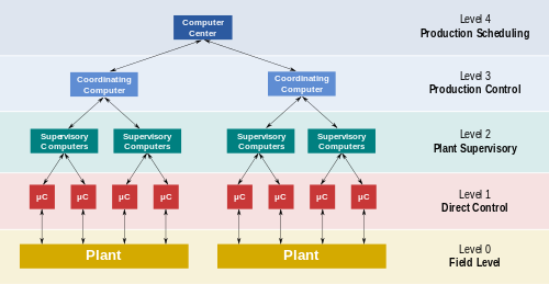
Functional levels of a manufacturing control operation

The key attribute of a DCS is its reliability due to the distribution of the control processing around nodes in the system. This mitigates a single processor failure. If a processor fails, it will only affect one section of the plant process, as opposed to a failure of a central computer which would affect the whole process. This distribution of computing power local to the field Input/Output (I/O) connection racks also ensures fast controller processing times by removing possible network and central processing delays.

The accompanying diagram is a general model which shows functional manufacturing levels using computerised control.

Referring to the diagram;

  • Level 0 contains the field devices such as flow and temperature sensors, and final control elements, such as control valves
  • Level 1 contains the industrialised Input/Output (I/O) modules, and their associated distributed electronic processors.
  • Level 2 contains the supervisory computers, which collect information from processor nodes on the system, and provide the operator control screens.
  • Level 3 is the production control level, which does not directly control the process, but is concerned with monitoring production and monitoring targets
  • Level 4 is the production scheduling level.

Levels 1 and 2 are the functional levels of a traditional DCS, in which all equipment are part of an integrated system from a single manufacturer.

Levels 3 and 4 are not strictly process control in the traditional sense, but where production control and scheduling takes place.

Technical points

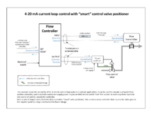
Example of a continuous flow control loop. Signalling is by industry standard 4–20 mA current loops, and a "smart" valve positioner ensures the control valve operates correctly.

The processor nodes and operator graphical displays are connected over proprietary or industry standard networks, and network reliability is increased by dual redundancy cabling over diverse routes. This distributed topology also reduces the amount of field cabling by siting the I/O modules and their associated processors close to the process plant.

The processors receive information from input modules, process the information and decide control actions to be signalled by the output modules. The field inputs and outputs can be analog signals e.g. 4–20 mA DC current loop or two-state signals that switch either "on" or "off", such as relay contacts or a semiconductor switch.

DCSs are connected to sensors and actuators and use setpoint control to control the flow of material through the plant. A typical application is a PID controller fed by a flow meter and using a control valve as the final control element. The DCS sends the setpoint required by the process to the controller which instructs a valve to operate so that the process reaches and stays at the desired setpoint. (see 4–20 mA schematic for example).

Large oil refineries and chemical plants have several thousand I/O points and employ very large DCS. Processes are not limited to fluidic flow through pipes, however, and can also include things like paper machines and their associated quality controls, variable speed drives and motor control centers, cement kilns, mining operations, ore processing facilities, and many others.

DCSs in very high reliability applications can have dual redundant processors with "hot" switch over on fault, to enhance the reliability of the control system.

Although 4–20 mA has been the main field signalling standard, modern DCS systems can also support fieldbus digital protocols, such as Foundation Fieldbus, profibus, HART, modbus, PC Link, etc.

Modern DCSs also support neural networks and fuzzy logic applications. Recent research focuses on the synthesis of optimal distributed controllers, which optimizes a certain H-infinity or the H 2 control criterion.

Typical applications

Distributed control systems (DCS) are dedicated systems used in manufacturing processes that are continuous or batch-oriented.

Processes where a DCS might be used include:

History

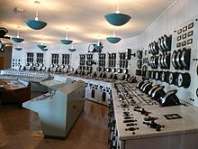
A pre-DCS era central control room. Whilst the controls are centralised in one place, they are still discrete and not integrated into one system.
 
A DCS control room where plant information and controls are displayed on computer graphics screens. The operators are seated as they can view and control any part of the process from their screens, whilst retaining a plant overview.

Evolution of process control operations

Process control of large industrial plants has evolved through many stages. Initially, control would be from panels local to the process plant. However this required a large manpower resource to attend to these dispersed panels, and there was no overall view of the process. The next logical development was the transmission of all plant measurements to a permanently-manned central control room. Effectively this was the centralisation of all the localised panels, with the advantages of lower manning levels and easier overview of the process. Often the controllers were behind the control room panels, and all automatic and manual control outputs were transmitted back to plant. However, whilst providing a central control focus, this arrangement was inflexible as each control loop had its own controller hardware, and continual operator movement within the control room was required to view different parts of the process.

With the coming of electronic processors and graphic displays it became possible to replace these discrete controllers with computer-based algorithms, hosted on a network of input/output racks with their own control processors. These could be distributed around plant, and communicate with the graphic display in the control room or rooms. The distributed control system was born.

The introduction of DCSs allowed easy interconnection and re-configuration of plant controls such as cascaded loops and interlocks, and easy interfacing with other production computer systems. It enabled sophisticated alarm handling, introduced automatic event logging, removed the need for physical records such as chart recorders, allowed the control racks to be networked and thereby located locally to plant to reduce cabling runs, and provided high level overviews of plant status and production levels.

Origins

Early minicomputers were used in the control of industrial processes since the beginning of the 1960s. The IBM 1800, for example, was an early computer that had input/output hardware to gather process signals in a plant for conversion from field contact levels (for digital points) and analog signals to the digital domain.

The first industrial control computer system was built 1959 at the Texaco Port Arthur, Texas, refinery with an RW-300 of the Ramo-Wooldridge Company.

In 1975, both Yamatake-Honeywelland Japanese electrical engineering firm Yokogawa introduced their own independently produced DCS's - TDC 2000 and CENTUM systems, respectively. US-based Bristol also introduced their UCS 3000 universal controller in 1975. In 1978 Valmet introduced their own DCS system called Damatic (latest generation named Valmet DNA). In 1980, Bailey (now part of ABB) introduced the NETWORK 90 system, Fisher Controls (now part of Emerson Electric) introduced the PROVoX system, Fischer & Porter Company (now also part of ABB) introduced DCI-4000 (DCI stands for Distributed Control Instrumentation).

The DCS largely came about due to the increased availability of microcomputers and the proliferation of microprocessors in the world of process control. Computers had already been applied to process automation for some time in the form of both direct digital control (DDC) and setpoint control. In the early 1970s Taylor Instrument Company, (now part of ABB) developed the 1010 system, Foxboro the FOX1 system, Fisher Controls the DC2 system and Bailey Controls the 1055 systems. All of these were DDC applications implemented within minicomputers (DEC PDP-11, Varian Data Machines, MODCOMP etc.) and connected to proprietary Input/Output hardware. Sophisticated (for the time) continuous as well as batch control was implemented in this way. A more conservative approach was setpoint control, where process computers supervised clusters of analog process controllers. A workstation provided visibility into the process using text and crude character graphics. Availability of a fully functional graphical user interface was a way away.

Development

Central to the DCS model was the inclusion of control function blocks. Function blocks evolved from early, more primitive DDC concepts of "Table Driven" software. One of the first embodiments of object-oriented software, function blocks were self-contained "blocks" of code that emulated analog hardware control components and performed tasks that were essential to process control, such as execution of PID algorithms. Function blocks continue to endure as the predominant method of control for DCS suppliers, and are supported by key technologies such as Foundation Fieldbus today.

Midac Systems, of Sydney, Australia, developed an objected-oriented distributed direct digital control system in 1982. The central system ran 11 microprocessors sharing tasks and common memory and connected to a serial communication network of distributed controllers each running two Z80s. The system was installed at the University of Melbourne.

Digital communication between distributed controllers, workstations and other computing elements (peer to peer access) was one of the primary advantages of the DCS. Attention was duly focused on the networks, which provided the all-important lines of communication that, for process applications, had to incorporate specific functions such as determinism and redundancy. As a result, many suppliers embraced the IEEE 802.4 networking standard. This decision set the stage for the wave of migrations necessary when information technology moved into process automation and IEEE 802.3 rather than IEEE 802.4 prevailed as the control LAN.

The network-centric era of the 1980s

In the 1980s, users began to look at DCSs as more than just basic process control. A very early example of a Direct Digital Control DCS was completed by the Australian business Midac in 1981–82 using R-Tec Australian designed hardware. The system installed at the University of Melbourne used a serial communications network, connecting campus buildings back to a control room "front end". Each remote unit ran two Z80 microprocessors, while the front end ran eleven Z80s in a parallel processing configuration with paged common memory to share tasks and that could run up to 20,000 concurrent control objects.

It was believed that if openness could be achieved and greater amounts of data could be shared throughout the enterprise that even greater things could be achieved. The first attempts to increase the openness of DCSs resulted in the adoption of the predominant operating system of the day: UNIX. UNIX and its companion networking technology TCP-IP were developed by the US Department of Defense for openness, which was precisely the issue the process industries were looking to resolve.

As a result, suppliers also began to adopt Ethernet-based networks with their own proprietary protocol layers. The full TCP/IP standard was not implemented, but the use of Ethernet made it possible to implement the first instances of object management and global data access technology. The 1980s also witnessed the first PLCs integrated into the DCS infrastructure. Plant-wide historians also emerged to capitalize on the extended reach of automation systems. The first DCS supplier to adopt UNIX and Ethernet networking technologies was Foxboro, who introduced the I/A Series system in 1987.

The application-centric era of the 1990s

The drive toward openness in the 1980s gained momentum through the 1990s with the increased adoption of commercial off-the-shelf (COTS) components and IT standards. Probably the biggest transition undertaken during this time was the move from the UNIX operating system to the Windows environment. While the realm of the real time operating system (RTOS) for control applications remains dominated by real time commercial variants of UNIX or proprietary operating systems, everything above real-time control has made the transition to Windows.

The introduction of Microsoft at the desktop and server layers resulted in the development of technologies such as OLE for process control (OPC), which is now a de facto industry connectivity standard. Internet technology also began to make its mark in automation and the world, with most DCS HMI supporting Internet connectivity. The 1990s were also known for the "Fieldbus Wars", where rival organizations competed to define what would become the IEC fieldbus standard for digital communication with field instrumentation instead of 4–20 milliamp analog communications. The first fieldbus installations occurred in the 1990s. Towards the end of the decade, the technology began to develop significant momentum, with the market consolidated around Ethernet I/P, Foundation Fieldbus and Profibus PA for process automation applications. Some suppliers built new systems from the ground up to maximize functionality with fieldbus, such as Rockwell PlantPAx System, Honeywell with Experion & Plantscape SCADA systems, ABB with System 800xA, Emerson Process Management with the Emerson Process Management DeltaV control system, Siemens with the SPPA-T3000 or Simatic PCS 7, Forbes Marshall with the Microcon+ control system and Azbil Corporation with the Harmonas-DEO system. Fieldbus technics have been used to integrate machine, drives, quality and condition monitoring applications to one DCS with Valmet DNA system.

The impact of COTS, however, was most pronounced at the hardware layer. For years, the primary business of DCS suppliers had been the supply of large amounts of hardware, particularly I/O and controllers. The initial proliferation of DCSs required the installation of prodigious amounts of this hardware, most of it manufactured from the bottom up by DCS suppliers. Standard computer components from manufacturers such as Intel and Motorola, however, made it cost prohibitive for DCS suppliers to continue making their own components, workstations, and networking hardware.

As the suppliers made the transition to COTS components, they also discovered that the hardware market was shrinking fast. COTS not only resulted in lower manufacturing costs for the supplier, but also steadily decreasing prices for the end users, who were also becoming increasingly vocal over what they perceived to be unduly high hardware costs. Some suppliers that were previously stronger in the PLC business, such as Rockwell Automation and Siemens, were able to leverage their expertise in manufacturing control hardware to enter the DCS marketplace with cost effective offerings, while the stability/scalability/reliability and functionality of these emerging systems are still improving. The traditional DCS suppliers introduced new generation DCS System based on the latest Communication and IEC Standards, which resulting in a trend of combining the traditional concepts/functionalities for PLC and DCS into a one for all solution—named "Process Automation System" (PAS). The gaps among the various systems remain at the areas such as: the database integrity, pre-engineering functionality, system maturity, communication transparency and reliability. While it is expected the cost ratio is relatively the same (the more powerful the systems are, the more expensive they will be), the reality of the automation business is often operating strategically case by case. The current next evolution step is called Collaborative Process Automation Systems.

To compound the issue, suppliers were also realizing that the hardware market was becoming saturated. The life cycle of hardware components such as I/O and wiring is also typically in the range of 15 to over 20 years, making for a challenging replacement market. Many of the older systems that were installed in the 1970s and 1980s are still in use today, and there is a considerable installed base of systems in the market that are approaching the end of their useful life. Developed industrial economies in North America, Europe, and Japan already had many thousands of DCSs installed, and with few if any new plants being built, the market for new hardware was shifting rapidly to smaller, albeit faster growing regions such as China, Latin America, and Eastern Europe.

Because of the shrinking hardware business, suppliers began to make the challenging transition from a hardware-based business model to one based on software and value-added services. It is a transition that is still being made today. The applications portfolio offered by suppliers expanded considerably in the '90s to include areas such as production management, model-based control, real-time optimization, plant asset management (PAM), Real-time performance management (RPM) tools, alarm management, and many others. To obtain the true value from these applications, however, often requires a considerable service content, which the suppliers also provide.

Modern systems (2010 onwards)

The latest developments in DCS include the following new technologies:

  1. Wireless systems and protocols 
  2. Remote transmission, logging and data historian
  3. Mobile interfaces and controls
  4. Embedded web-servers

Increasingly, and ironically, DCS are becoming centralised at plant level, with the ability to log into the remote equipment. This enables operator to control both at enterprise level ( macro ) and at the equipment level (micro), both within and outside the plant, because the importance of the physical location drops due to interconnectivity primarily thanks to wireless and remote access.

The more wireless protocols are developed and refined, the more they are included in DCS. DCS controllers are now often equipped with embedded servers and provide on-the-go web access. Whether DCS will lead Industrial Internet of Things (IIOT) or borrow key elements from remains to be seen.

Many vendors provide the option of a mobile HMI, ready for both Android and iOS. With these interfaces, the threat of security breaches and possible damage to plant and process are now very real.

Introduction to entropy

From Wikipedia, the free encyclopedia https://en.wikipedia.org/wiki/Introduct...