Search This Blog

Tuesday, August 8, 2023

Bézier curve

From Wikipedia, the free encyclopedia
https://en.wikipedia.org/wiki/B%C3%A9zier_curve
Cubic Bézier curve with four control points
The basis functions on the range t in [0,1] for cubic Bézier curves: blue: y = (1 − t)3, green: y = 3(1 − t)2t, red: y = 3(1 − t)t2, and cyan: y = t3.

A Bézier curve (/ˈbɛz.i./ BEH-zee-ay) is a parametric curve used in computer graphics and related fields. A set of discrete "control points" defines a smooth, continuous curve by means of a formula. Usually the curve is intended to approximate a real-world shape that otherwise has no mathematical representation or whose representation is unknown or too complicated. The Bézier curve is named after French engineer Pierre Bézier (1910–1999), who used it in the 1960s for designing curves for the bodywork of Renault cars. Other uses include the design of computer fonts and animation. Bézier curves can be combined to form a Bézier spline, or generalized to higher dimensions to form Bézier surfaces. The Bézier triangle is a special case of the latter.

In vector graphics, Bézier curves are used to model smooth curves that can be scaled indefinitely. "Paths", as they are commonly referred to in image manipulation programs, are combinations of linked Bézier curves. Paths are not bound by the limits of rasterized images and are intuitive to modify.

Bézier curves are also used in the time domain, particularly in animation, user interface design and smoothing cursor trajectory in eye gaze controlled interfaces. For example, a Bézier curve can be used to specify the velocity over time of an object such as an icon moving from A to B, rather than simply moving at a fixed number of pixels per step. When animators or interface designers talk about the "physics" or "feel" of an operation, they may be referring to the particular Bézier curve used to control the velocity over time of the move in question.

This also applies to robotics where the motion of a welding arm, for example, should be smooth to avoid unnecessary wear.

Invention

The mathematical basis for Bézier curves—the Bernstein polynomials—was established in 1912, but the polynomials were not applied to graphics until some 50 years later when mathematician Paul de Casteljau in 1959 developed de Casteljau's algorithm, a numerically stable method for evaluating the curves, and became the first to apply them to computer-aided design at French automaker Citroën. Yet, de Casteljau's method was patented in France but not published until the 1980s while the Bézier polynomials were widely publicised in the 1960s by the French engineer Pierre Bézier, who discovered them independently and used them to design automobile bodies at Renault.

Specific cases

A Bézier curve is defined by a set of control points P0 through Pn, where n is called the order of the curve (n = 1 for linear, 2 for quadratic, 3 for cubic, etc.). The first and last control points are always the endpoints of the curve; however, the intermediate control points generally do not lie on the curve. The sums in the following sections are to be understood as affine combinations – that is, the coefficients sum to 1.

Linear Bézier curves

Given distinct points P0 and P1, a linear Bézier curve is simply a line between those two points. The curve is given by

and is equivalent to linear interpolation. The quantity represents the displacement vector from the start point to the end point.

Quadratic Bézier curves

Quadratic Béziers in string art: The end points () and control point (×) define the quadratic Bézier curve ().

A quadratic Bézier curve is the path traced by the function B(t), given points P0, P1, and P2,

,

which can be interpreted as the linear interpolant of corresponding points on the linear Bézier curves from P0 to P1 and from P1 to P2 respectively. Rearranging the preceding equation yields:

This can be written in a way that highlights the symmetry with respect to P1:

Which immediately gives the derivative of the Bézier curve with respect to t:

from which it can be concluded that the tangents to the curve at P0 and P2 intersect at P1. As t increases from 0 to 1, the curve departs from P0 in the direction of P1, then bends to arrive at P2 from the direction of P1.

The second derivative of the Bézier curve with respect to t is

Cubic Bézier curves

Four points P0, P1, P2 and P3 in the plane or in higher-dimensional space define a cubic Bézier curve. The curve starts at P0 going toward P1 and arrives at P3 coming from the direction of P2. Usually, it will not pass through P1 or P2; these points are only there to provide directional information. The distance between P1 and P2 determines "how far" and "how fast" the curve moves towards P1 before turning towards P2.

Writing BPi,Pj,Pk(t) for the quadratic Bézier curve defined by points Pi, Pj, and Pk, the cubic Bézier curve can be defined as an affine combination of two quadratic Bézier curves:

The explicit form of the curve is:

For some choices of P1 and P2 the curve may intersect itself, or contain a cusp.

Any series of 4 distinct points can be converted to a cubic Bézier curve that goes through all 4 points in order. Given the starting and ending point of some cubic Bézier curve, and the points along the curve corresponding to t = 1/3 and t = 2/3, the control points for the original Bézier curve can be recovered.

The derivative of the cubic Bézier curve with respect to t is

The second derivative of the Bézier curve with respect to t is

General definition

Bézier curves can be defined for any degree n.

Recursive definition

A recursive definition for the Bézier curve of degree n expresses it as a point-to-point linear combination (linear interpolation) of a pair of corresponding points in two Bézier curves of degree n − 1.

Let denote the Bézier curve determined by any selection of points P0, P1, ..., Pk. Then to start,

This recursion is elucidated in the animations below.

Explicit definition

The formula can be expressed explicitly as follows (where t0 and (1-t)0 are extended continuously to be 1 throughout [0,1]):

where are the binomial coefficients.

For example, when n = 5:

Terminology

Some terminology is associated with these parametric curves. We have

where the polynomials

are known as Bernstein basis polynomials of degree n.

t0 = 1, (1 − t)0 = 1, and the binomial coefficient, , is:

The points Pi are called control points for the Bézier curve. The polygon formed by connecting the Bézier points with lines, starting with P0 and finishing with Pn, is called the Bézier polygon (or control polygon). The convex hull of the Bézier polygon contains the Bézier curve.

Polynomial form

Sometimes it is desirable to express the Bézier curve as a polynomial instead of a sum of less straightforward Bernstein polynomials. Application of the binomial theorem to the definition of the curve followed by some rearrangement will yield

where

This could be practical if can be computed prior to many evaluations of ; however one should use caution as high order curves may lack numeric stability (de Casteljau's algorithm should be used if this occurs). Note that the empty product is 1.

Properties
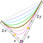
A cubic Bézier curve (yellow) can be made identical to a quadratic one (black) by
1. copying the end points, and
2. placing its 2 middle control points (yellow circles) 2/3 along line segments from the end points to the quadratic curve's middle control point (black rectangle).
  • The curve begins at and ends at ; this is the so-called endpoint interpolation property.
  • The curve is a line if and only if all the control points are collinear.
  • The start and end of the curve is tangent to the first and last section of the Bézier polygon, respectively.
  • A curve can be split at any point into two subcurves, or into arbitrarily many subcurves, each of which is also a Bézier curve.
  • Some curves that seem simple, such as the circle, cannot be described exactly by a Bézier or piecewise Bézier curve; though a four-piece cubic Bézier curve can approximate a circle (see composite Bézier curve), with a maximum radial error of less than one part in a thousand, when each inner control point (or offline point) is the distance horizontally or vertically from an outer control point on a unit circle. More generally, an n-piece cubic Bézier curve can approximate a circle, when each inner control point is the distance from an outer control point on a unit circle, where (i.e. ), and .
  • Every quadratic Bézier curve is also a cubic Bézier curve, and more generally, every degree n Bézier curve is also a degree m curve for any m > n. In detail, a degree n curve with control points is equivalent (including the parametrization) to the degree n + 1 curve with control points , where , and define , .
  • Bézier curves have the variation diminishing property. What this means in intuitive terms is that a Bézier curve does not "undulate" more than the polygon of its control points, and may actually "undulate" less than that.
  • There is no local control in degree n Bézier curves—meaning that any change to a control point requires recalculation of and thus affects the aspect of the entire curve, "although the further that one is from the control point that was changed, the smaller is the change in the curve."
  • A Bézier curve of order higher than two may intersect itself or have a cusp for certain choices of the control points.

Second-order curve is a parabolic segment
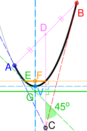
Equivalence of a quadratic Bézier curve and a parabolic segment

A quadratic Bézier curve is also a segment of a parabola. As a parabola is a conic section, some sources refer to quadratic Béziers as "conic arcs". With reference to the figure on the right, the important features of the parabola can be derived as follows:

  1. Tangents to the parabola at the endpoints of the curve (A and B) intersect at its control point (C).
  2. If D is the midpoint of AB, the tangent to the curve which is perpendicular to CD (dashed cyan line) defines its vertex (V). Its axis of symmetry (dash-dot cyan) passes through V and is perpendicular to the tangent.
  3. E is either point on the curve with a tangent at 45° to CD (dashed green). If G is the intersection of this tangent and the axis, the line passing through G and perpendicular to CD is the directrix (solid green).
  4. The focus (F) is at the intersection of the axis and a line passing through E and perpendicular to CD (dotted yellow). The latus rectum is the line segment within the curve (solid yellow).

Derivative

The derivative for a curve of order n is

Constructing Bézier curves

Linear curves

Let t denote the fraction of progress (from 0 to 1) the point B(t) has made along its traversal from P0 to P1. For example, when t=0.25, B(t) is one quarter of the way from point P0 to P1. As t varies from 0 to 1, B(t) draws a line from P0 to P1.

Animation of a linear Bézier curve, t in [0,1]

Quadratic curves

For quadratic Bézier curves one can construct intermediate points Q0 and Q1 such that as t varies from 0 to 1:

  • Point Q0(t) varies from P0 to P1 and describes a linear Bézier curve.
  • Point Q1(t) varies from P1 to P2 and describes a linear Bézier curve.
  • Point B(t) is interpolated linearly between Q0(t) to Q1(t) and describes a quadratic Bézier curve.
Construction of a quadratic Bézier curve
Animation of a quadratic Bézier curve, t in [0,1]
Construction of a quadratic Bézier curve
Animation of a quadratic Bézier curve, t in [0,1]

Higher-order curves

For higher-order curves one needs correspondingly more intermediate points. For cubic curves one can construct intermediate points Q0, Q1, and Q2 that describe linear Bézier curves, and points R0 and R1 that describe quadratic Bézier curves:

Construction of a cubic Bézier curve
Animation of a cubic Bézier curve, t in [0,1]
Construction of a cubic Bézier curve
Animation of a cubic Bézier curve, t in [0,1]

For fourth-order curves one can construct intermediate points Q0, Q1, Q2 and Q3 that describe linear Bézier curves, points R0, R1 and R2 that describe quadratic Bézier curves, and points S0 and S1 that describe cubic Bézier curves:
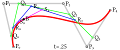
Construction of a quartic Bézier curve
Animation of a quartic Bézier curve, t in [0,1]
Construction of a quartic Bézier curve
Animation of a quartic Bézier curve, t in [0,1]

For fifth-order curves, one can construct similar intermediate points.
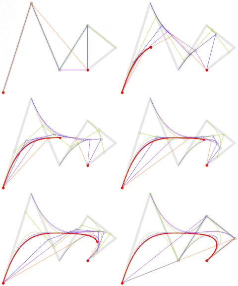
Animation of the construction of a fifth-order Bézier curve
Animation of a fifth-order Bézier curve, t in [0,1] in red. The Bézier curves for each of the lower orders are also shown.

These representations rest on the process used in De Casteljau's algorithm to calculate Bézier curves.

Offsets (or stroking) of Bézier curves

The curve at a fixed offset from a given Bézier curve, called an offset or parallel curve in mathematics (lying "parallel" to the original curve, like the offset between rails in a railroad track), cannot be exactly formed by a Bézier curve (except in some trivial cases). In general, the two-sided offset curve of a cubic Bézier is a 10th-order algebraic curve and more generally for a Bézier of degree n the two-sided offset curve is an algebraic curve of degree 4n − 2. However, there are heuristic methods that usually give an adequate approximation for practical purposes.

In the field of vector graphics, painting two symmetrically distanced offset curves is called stroking (the Bézier curve or in general a path of several Bézier segments). The conversion from offset curves to filled Bézier contours is of practical importance in converting fonts defined in Metafont, which require stroking of Bézier curves, to the more widely used PostScript type 1 fonts, which only require (for efficiency purposes) the mathematically simpler operation of filling a contour defined by (non-self-intersecting) Bézier curves.

Degree elevation

A Bézier curve of degree n can be converted into a Bézier curve of degree n + 1 with the same shape. This is useful if software supports Bézier curves only of specific degree. For example, systems that can only work with cubic Bézier curves can implicitly work with quadratic curves by using their equivalent cubic representation.

To do degree elevation, we use the equality Each component is multiplied by (1 − t) and t, thus increasing a degree by one, without changing the value. Here is the example of increasing degree from 2 to 3.

For arbitrary n we use equalities

Therefore:

introducing arbitrary and .

Therefore, new control points are

Repeated degree elevation

The concept of degree elevation can be repeated on a control polygon R to get a sequence of control polygons R, R1, R2, and so on. After r degree elevations, the polygon Rr has the vertices P0,r, P1,r, P2,r, ..., Pn+r,r given by 

It can also be shown that for the underlying Bézier curve B,

Rational Bézier curves
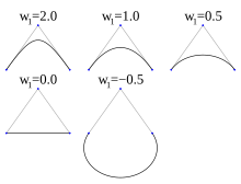
Segments of conic sections represented exactly by rational Bézier curves

The rational Bézier curve adds adjustable weights to provide closer approximations to arbitrary shapes. The numerator is a weighted Bernstein-form Bézier curve and the denominator is a weighted sum of Bernstein polynomials. Rational Bézier curves can, among other uses, be used to represent segments of conic sections exactly, including circular arcs.

Given n + 1 control points P0, ..., Pn, the rational Bézier curve can be described by

or simply

The expression can be extended by using number systems besides reals for the weights. In the complex plane the points {1}, {-1}, and {1} with weights {}, {1}, and {} generate a full circle with radius one. For curves with points and weights on a circle, the weights can be scaled without changing the curve's shape. Scaling the central weight of the above curve by 1.35508 gives a more uniform parameterization.

Applications

Computer graphics

Bézier path in Adobe Illustrator

Bézier curves are widely used in computer graphics to model smooth curves. As the curve is completely contained in the convex hull of its control points, the points can be graphically displayed and used to manipulate the curve intuitively. Affine transformations such as translation and rotation can be applied on the curve by applying the respective transform on the control points of the curve.

Quadratic and cubic Bézier curves are most common. Higher degree curves are more computationally expensive to evaluate. When more complex shapes are needed, low order Bézier curves are patched together, producing a composite Bézier curve. A composite Bézier curve is commonly referred to as a "path" in vector graphics languages (like PostScript), vector graphics standards (like SVG) and vector graphics programs (like Artline, Timeworks Publisher, Adobe Illustrator, CorelDraw, Inkscape, and Allegro). In order to join Bézier curves into a composite Bézier curve without kinks, a property called G1 continuous, it suffices to force the control point at which two constituent Bézier curves meet to lie on the line defined by the two control points on either side.

Abstract composition of cubic Bézier curves ray-traced in 3D. Ray intersection with swept volumes along curves is calculated with Phantom Ray-Hair Intersector algorithm.

The simplest method for scan converting (rasterizing) a Bézier curve is to evaluate it at many closely spaced points and scan convert the approximating sequence of line segments. However, this does not guarantee that the rasterized output looks sufficiently smooth, because the points may be spaced too far apart. Conversely it may generate too many points in areas where the curve is close to linear. A common adaptive method is recursive subdivision, in which a curve's control points are checked to see if the curve approximates a line to within a small tolerance. If not, the curve is subdivided parametrically into two segments, 0 ≤ t ≤ 0.5 and 0.5 ≤ t ≤ 1, and the same procedure is applied recursively to each half. There are also forward differencing methods, but great care must be taken to analyse error propagation.

Analytical methods where a Bézier is intersected with each scan line involve finding roots of cubic polynomials (for cubic Béziers) and dealing with multiple roots, so they are not often used in practice.

The rasterisation algorithm used in Metafont is based on discretising the curve, so that it is approximated by a sequence of "rook moves" that are purely vertical or purely horizontal, along the pixel boundaries. To that end, the plane is first split into eight 45° sectors (by the coordinate axes and the two lines ), then the curve is decomposed into smaller segments such that the direction of a curve segment stays within one sector; since the curve velocity is a second degree polynomial, finding the values where it is parallel to one of these lines can be done by solving quadratic equations. Within each segment, either horizontal or vertical movement dominates, and the total number of steps in either direction can be read off from the endpoint coordinates; in for example the 0–45° sector horizontal movement to the right dominates, so it only remains to decide between which steps to the right the curve should make a step up.

There is also a modified curve form of Bresenham's line drawing algorithm by Zingl that performs this rasterization by subdividing the curve into rational pieces and calculating the error at each pixel location such that it either travels at a 45° angle or straight depending on compounding error as it iterates through the curve. This reduces the next step calculation to a series of integer additions and subtractions.

Animation

In animation applications, such as Adobe Flash and Synfig, Bézier curves are used to outline, for example, movement. Users outline the wanted path in Bézier curves, and the application creates the needed frames for the object to move along the path.

In 3D animation, Bézier curves are often used to define 3D paths as well as 2D curves for keyframe interpolation. Bézier curves are now very frequently used to control the animation easing in CSS, JavaScript, JavaFx and Flutter SDK.

Fonts

TrueType fonts use composite Bézier curves composed of quadratic Bézier curves. Other languages and imaging tools (such as PostScript, Asymptote, Metafont, and SVG) use composite Béziers composed of cubic Bézier curves for drawing curved shapes. OpenType fonts can use either kind of curve, depending on which font technology underlies the OpenType wrapper.

Font engines, like FreeType, draw the font's curves (and lines) on a pixellated surface using a process known as font rasterization. Typically font engines and vector graphics engines render Bézier curves by splitting them recursively up to the point where the curve is flat enough to be drawn as a series of linear or circular segments. The exact splitting algorithm is implementation dependent, only the flatness criteria must be respected to reach the necessary precision and to avoid non-monotonic local changes of curvature. The "smooth curve" feature of charts in Microsoft Excel also uses this algorithm.

Because arcs of circles and ellipses cannot be exactly represented by Bézier curves, they are first approximated by Bézier curves, which are in turn approximated by arcs of circles. This is inefficient as there exists also approximations of all Bézier curves using arcs of circles or ellipses, which can be rendered incrementally with arbitrary precision. Another approach, used by modern hardware graphics adapters with accelerated geometry, can convert exactly all Bézier and conic curves (or surfaces) into NURBS, that can be rendered incrementally without first splitting the curve recursively to reach the necessary flatness condition. This approach also preserves the curve definition under all linear or perspective 2D and 3D transforms and projections.

Robotics

Bézier curves can be used in robotics to produce trajectories of an end-effector due to the virtue of the control polygon’s ability to give a clear indication of whether the path is colliding with any nearby obstacle or object. Furthermore, joint space trajectories can be accurately differentiated using Bézier curves. Consequently, the derivatives of joint space trajectories are used in the calculation of the dynamics and control effort (torque profiles) of the robotic manipulator.

Monday, August 7, 2023

NASA Deep Space Network

From Wikipedia, the free encyclopedia
https://en.wikipedia.org/wiki/NASA_Deep_Space_Network

Deep Space Network
Insignia for the Deep Space Network's 50th anniversary celebrations (1963–2013)
Alternative namesNASA Deep Space Network Edit this at Wikidata
OrganizationInterplanetary Network Directorate
(NASA / JPL)
LocationPasadena, Los Angeles County, California
Coordinates34°12′6.1″N 118°10′18″W
EstablishedOctober 1, 1958
64 years ago
Websitedeepspace.jpl.nasa.gov
Telescopes
Goldstone Deep Space Communications ComplexBarstow, California, United States
Madrid Deep Space Communications ComplexRobledo de Chavela, Community of Madrid, Spain
Canberra Deep Space Communication ComplexCanberra, Australia

The NASA Deep Space Network (DSN) is a worldwide network of American spacecraft communication ground segment facilities, located in the United States (California), Spain (Madrid), and Australia (Canberra), that supports NASA's interplanetary spacecraft missions. It also performs radio and radar astronomy observations for the exploration of the Solar System and the universe, and supports selected Earth-orbiting missions. DSN is part of the NASA Jet Propulsion Laboratory (JPL).

General information

Map this section's coordinates using: OpenStreetMap

Download coordinates as:

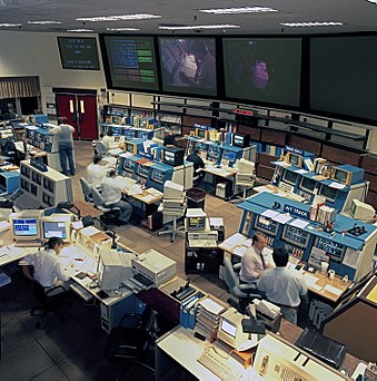
Deep Space Network Operations Center at JPL, Pasadena (California) in 1993.

DSN currently consists of three deep-space communications facilities located such that a distant spacecraft is always in view of at least one station. They are:

Each facility is situated in semi-mountainous, bowl-shaped terrain to help shield against radio frequency interference. The strategic placement of the stations permits constant observation of spacecraft as the Earth rotates, which helps to make the DSN the largest and most sensitive scientific telecommunications system in the world.

The DSN supports NASA's contribution to the scientific investigation of the Solar System: It provides a two-way communications link that guides and controls various NASA uncrewed interplanetary space probes, and brings back the images and new scientific information these probes collect. All DSN antennas are steerable, high-gain, parabolic reflector antennas. The antennas and data delivery systems make it possible to:

  • acquire telemetry data from spacecraft.
  • transmit commands to spacecraft.
  • upload software modifications to spacecraft.
  • track spacecraft position and velocity.
  • perform Very Long Baseline Interferometry observations.
  • measure variations in radio waves for radio science experiments.
  • gather science data.
  • monitor and control the performance of the network.

Other countries and organizations also run deep space networks. The DSN operates according to the standards of the Consultative Committee for Space Data Systems, as do most other deep space networks, and hence the DSN is able to inter-operate with the networks of other space agencies. These include the Soviet Deep Space Network, the Chinese Deep Space Network, the Indian Deep Space Network, the Japanese Deep Space Network, and the ESTRACK of the European Space Agency. These agencies often cooperate for better mission coverage. In particular, DSN has a cross-support agreement with ESA that allows mutual use of both networks for more effectiveness and reduced risk. In addition, radio astronomy facilities, such as Parkes Observatory or the Green Bank Telescope, are sometimes used to supplement the antennas of the DSN.

Operations control center

The antennas at all three DSN Complexes communicate directly with the Deep Space Operations Center (also known as Deep Space Network operations control center) located at the JPL facilities in Pasadena, California.

In the early years, the operations control center did not have a permanent facility. It was a provisional setup with numerous desks and phones installed in a large room near the computers used to calculate orbits. In July 1961, NASA started the construction of the permanent facility, Space Flight Operations Facility (SFOF). The facility was completed in October 1963 and dedicated on May 14, 1964. In the initial setup of the SFOF, there were 31 consoles, 100 closed-circuit television cameras, and more than 200 television displays to support Ranger 6 to Ranger 9 and Mariner 4.

Currently, the operations center personnel at SFOF monitor and direct operations, and oversee the quality of spacecraft telemetry and navigation data delivered to network users. In addition to the DSN complexes and the operations center, a ground communications facility provides communications that link the three complexes to the operations center at JPL, to space flight control centers in the United States and overseas, and to scientists around the world.

Deep space

View from the Earth's north pole, showing the field of view of the main DSN antenna locations. Once a mission gets more than 30,000 km (19,000 mi) from Earth, it is al­ways in view of at least one of the stations.

Tracking vehicles in deep space is quite different from tracking missions in low Earth orbit (LEO). Deep space missions are visible for long periods of time from a large portion of the Earth's surface, and so require few stations (the DSN has only three main sites). These few stations, however, require huge antennas, ultra-sensitive receivers, and powerful transmitters in order to transmit and receive over the vast distances involved.

Deep space is defined in several different ways. According to a 1975 NASA report, the DSN was designed to communicate with "spacecraft traveling approximately 16,000 km (10,000 miles) from Earth to the farthest planets of the solar system." JPL diagrams state that at an altitude of 30,000 km (19,000 mi), a spacecraft is always in the field of view of one of the tracking stations.

The International Telecommunication Union, which sets aside various frequency bands for deep space and near Earth use, defines "deep space" to start at a distance of 2 million km (1.2 million mi) from the Earth's surface. Because the Moon, the Earth-moon Lagrange points, and the Earth–Sun Lagrangian points L1 and L2, are all closer than 2 million km from Earth (distances are here), they are considered near space and cannot use the ITU's deep space bands.

History

The forerunner of the DSN was established in January 1958, when JPL, then under contract to the U.S. Army, deployed portable radio tracking stations in Nigeria, Singapore, and California to receive telemetry and plot the orbit of the Army-launched Explorer 1, the first successful U.S. satellite. NASA was officially established on October 1, 1958, to consolidate the separately developing space-exploration programs of the US Army, US Navy, and US Air Force into one civilian organization.

On December 3, 1958, JPL was transferred from the US Army to NASA and given responsibility for the design and execution of lunar and planetary exploration programs using remotely controlled spacecraft. Shortly after the transfer, NASA established the concept of the Deep Space Network as a separately managed and operated communications system that would accommodate all deep space missions, thereby avoiding the need for each flight project to acquire and operate its own specialized space communications network. The DSN was given responsibility for its own research, development, and operation in support of all of its users. Under this concept, it has become a world leader in the development of low-noise receivers; large parabolic-dish antennas; tracking, telemetry, and command systems; digital signal processing; and deep space navigation. The Deep Space Network formally announced its intention to send missions into deep space on Christmas Eve 1963; it has remained in continuous operation in one capacity or another ever since.

The largest antennas of the DSN are often called on during spacecraft emergencies. Almost all spacecraft are designed so normal operation can be conducted on the smaller (and more economical) antennas of the DSN, but during an emergency the use of the largest antennas is crucial. This is because a troubled spacecraft may be forced to use less than its normal transmitter power, attitude control problems may preclude the use of high-gain antennas, and recovering every bit of telemetry is critical to assessing the health of the spacecraft and planning the recovery. The most famous example is the Apollo 13 mission, where limited battery power and inability to use the spacecraft's high-gain antennas reduced signal levels below the capability of the Manned Space Flight Network, and the use of the biggest DSN antennas (and the Australian Parkes Observatory radio telescope) was critical to saving the lives of the astronauts. While Apollo was also a US mission, DSN provides this emergency service to other space agencies as well, in a spirit of inter-agency and international cooperation. For example, the recovery of the Solar and Heliospheric Observatory (SOHO) mission of the European Space Agency (ESA) would not have been possible without the use of the largest DSN facilities.

DSN and the Apollo program

Although normally tasked with tracking uncrewed spacecraft, the Deep Space Network (DSN) also contributed to the communication and tracking of Apollo missions to the Moon, although primary responsibility was held by the Manned Space Flight Network (MSFN). The DSN designed the MSFN stations for lunar communication and provided a second antenna at each MSFN site (the MSFN sites were near the DSN sites for just this reason). Two antennas at each site were needed both for redundancy and because the beam widths of the large antennas needed were too small to encompass both the lunar orbiter and the lander at the same time. DSN also supplied some larger antennas as needed, in particular for television broadcasts from the Moon, and emergency communications such as Apollo 13.

Excerpt from a NASA report describing how the DSN and MSFN cooperated for Apollo:

Another critical step in the evolution of the Apollo Network came in 1965 with the advent of the DSN Wing concept. Originally, the participation of DSN 26-m antennas during an Apollo Mission was to be limited to a backup role. This was one reason why the MSFN 26-m sites were collocated with the DSN sites at Goldstone, Madrid, and Canberra. However, the presence of two, well-separated spacecraft during lunar operations stimulated the rethinking of the tracking and communication problem. One thought was to add a dual S-band RF system to each of the three 26-m MSFN antennas, leaving the nearby DSN 26-m antennas still in a backup role. Calculations showed, though, that a 26-m antenna pattern centered on the landed Lunar Module would suffer a 9-to-12 db loss at the lunar horizon, making tracking and data acquisition of the orbiting Command Service Module difficult, perhaps impossible. It made sense to use both the MSFN and DSN antennas simultaneously during the all-important lunar operations. JPL was naturally reluctant to compromise the objectives of its many uncrewed spacecraft by turning three of its DSN stations over to the MSFN for long periods. How could the goals of both Apollo and deep space exploration be achieved without building a third 26-m antenna at each of the three sites or undercutting planetary science missions?

The solution came in early 1965 at a meeting at NASA Headquarters, when Eberhardt Rechtin suggested what is now known as the "wing concept". The wing approach involves constructing a new section or "wing" to the main building at each of the three involved DSN sites. The wing would include a MSFN control room and the necessary interface equipment to accomplish the following:

  1. Permit tracking and two-way data transfer with either spacecraft during lunar operations.
  2. Permit tracking and two-way data transfer with the combined spacecraft during the flight to the Moon.
  3. Provide backup for the collocated MSFN site passive track (spacecraft to ground RF links) of the Apollo spacecraft during trans-lunar and trans-earth phases.

With this arrangement, the DSN station could be quickly switched from a deep-space mission to Apollo and back again. GSFC personnel would operate the MSFN equipment completely independently of DSN personnel. Deep space missions would not be compromised nearly as much as if the entire station's equipment and personnel were turned over to Apollo for several weeks.

The details of this cooperation and operation are available in a two-volume technical report from JPL.

Management

The network is a NASA facility and is managed and operated for NASA by JPL, which is part of the California Institute of Technology (Caltech). The Interplanetary Network Directorate (IND) manages the program within JPL and is charged with the development and operation of it. The IND is considered to be JPL's focal point for all matters relating to telecommunications, interplanetary navigation, information systems, information technology, computing, software engineering, and other relevant technologies. While the IND is best known for its duties relating to the Deep Space Network, the organization also maintains the JPL Advanced Multi-Mission Operations System (AMMOS) and JPL's Institutional Computing and Information Services (ICIS).

Peraton (formerly Harris Corporation) is under contract to JPL for the DSN's operations and maintenance. Peraton has responsibility for managing the Goldstone complex, operating the DSOC, and for DSN operations, mission planning, operations engineering, and logistics.

Antennas

70 m antenna at Goldstone, California.

Each complex consists of at least four deep space terminals equipped with ultra-sensitive receiving systems and large parabolic-dish antennas. There are:

Five of the 34-meter (112 ft) beam waveguide antennas were added to the system in the late 1990s. Three were located at Goldstone, and one each at Canberra and Madrid. A second 34-meter (112 ft) beam waveguide antenna (the network's sixth) was completed at the Madrid complex in 2004.

In order to meet the current and future needs of deep space communication services, a number of new Deep Space Station antennas had to be built at the existing Deep Space Network sites. At the Canberra Deep Space Communication Complex the first of these was completed in October 2014 (DSS35), with a second becoming operational in October 2016 (DSS36). A new 34 meter dish (DSS53) became operational at the Madrid complex in February 2022.

By 2025, the 70-meter antennas at all three locations will be decommissioned and replaced with 34-meter BWG antennas that will be arrayed. All systems will be upgraded to have X-band uplink capabilities and both X and Ka-band downlink capabilities.

Current signal processing capabilities

The Canberra Deep Space Communication Complex in 2008

The general capabilities of the DSN have not substantially changed since the beginning of the Voyager Interstellar Mission in the early 1990s. However, many advancements in digital signal processing, arraying and error correction have been adopted by the DSN.

The ability to array several antennas was incorporated to improve the data returned from the Voyager 2 Neptune encounter, and extensively used for the Galileo mission, when the spacecraft's high-gain antenna failed to deploy and as a result Galileo was forced to resort to operating solely off its low-gain antennas.

The DSN array currently available since the Galileo mission can link the 70-meter (230 ft) dish antenna at the Deep Space Network complex in Goldstone, California, with an identical antenna located in Australia, in addition to two 34-meter (112 ft) antennas at the Canberra complex. The California and Australia sites were used concurrently to pick up communications with Galileo.

Arraying of antennas within the three DSN locations is also used. For example, a 70-meter (230 ft) dish antenna can be arrayed with a 34-meter dish. For especially vital missions, like Voyager 2, non-DSN facilities normally used for radio astronomy can be added to the array. In particular, the Canberra 70-meter (230 ft) dish can be arrayed with the Parkes Radio Telescope in Australia; and the Goldstone 70-meter dish can be arrayed with the Very Large Array of antennas in New Mexico. Also, two or more 34-meter (112 ft) dishes at one DSN location are commonly arrayed together.

All the stations are remotely operated from a centralized Signal Processing Center at each complex. These Centers house the electronic subsystems that point and control the antennas, receive and process the telemetry data, transmit commands, and generate the spacecraft navigation data. Once the data are processed at the complexes, they are transmitted to JPL for further processing and for distribution to science teams over a modern communications network.

Especially at Mars, there are often many spacecraft within the beam width of an antenna. For operational efficiency, a single antenna can receive signals from multiple spacecraft at the same time. This capability is called Multiple Spacecraft Per Aperture, or MSPA. Currently, the DSN can receive up to 4 spacecraft signals at the same time, or MSPA-4. However, apertures cannot currently be shared for uplink. When two or more high-power carriers are used simultaneously, very high order intermodulation products fall in the receiver bands, causing interference to the much (25 orders of magnitude) weaker received signals. Therefore, only one spacecraft at a time can get an uplink, though up to 4 can be received.

Network limitations and challenges

70m antenna in Robledo de Chavela, Community of Madrid, Spain

There are a number of limitations to the current DSN, and a number of challenges going forward.

  • The Deep Space Network nodes are all on Earth. Therefore, data transmission rates from/to spacecraft and space probes are severely constrained due to the distances from Earth. For now it can connect with the Mars orbiters in the Mars Relay Network for faster and more flexible communications with spacecraft and landers on Mars. Adding dedicated communication satellites elsewhere in space, to handle multiparty, multi-mission use, such as the canceled Mars Telecommunications Orbiter, would increase flexibility towards some sort of Interplanetary Internet.
  • The need to support "legacy" missions that have remained operational beyond their original lifetimes but are still returning scientific data. Programs such as Voyager have been operating long past their original mission termination date. They also need some of the largest antennas.
  • Replacing major components can cause problems as it can leave an antenna out of service for months at a time.
  • The older 70 m antennas are reaching the end of their lives. At some point these will need to be replaced. The leading candidate for 70 m replacement had been an array of smaller dishes, but more recently the decision was taken to expand the provision of 34-meter (112 ft) BWG antennas at each complex to a total of 4. All the 34-meter HEF antennas have been replaced.
  • New spacecraft intended for missions beyond geocentric orbits are being equipped to use the beacon mode service, which allows such missions to operate without the DSN most of the time.

DSN and radio science

Illustration of Juno and Jupiter. Juno is in a polar orbit that takes it close to Jupiter as it passes from north to south, getting a view of both poles. During the GS experiment it must point its antenna at the Deep Space Network on Earth to pick up a special signal sent from DSN.

The DSN forms one portion of the radio sciences experiment included on most deep space missions, where radio links between spacecraft and Earth are used to investigate planetary science, space physics and fundamental physics. The experiments include radio occultations, gravity field determination and celestial mechanics, bistatic scattering, doppler wind experiments, solar corona characterization, and tests of fundamental physics.

For example, the Deep Space Network forms one component of the gravity science experiment on Juno. This includes special communication hardware on Juno and uses its communication system. The DSN radiates a Ka-band uplink, which is picked up by Juno's Ka-Band communication system and then processed by a special communication box called KaTS, and then this new signal is sent back the DSN. This allows the velocity of the spacecraft over time to be determined with a level of precision that allows a more accurate determination of the gravity field at planet Jupiter.

Another radio science experiment is REX on the New Horizons spacecraft to Pluto-Charon. REX received a signal from Earth as it was occulted by Pluto, to take various measurements of that system of bodies.

Very high frequency

From Wikipedia, the free encyclopedia
Very high frequency
Frequency range
30 MHz to 300 MHz
Wavelength range
10 to 1 m
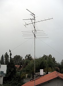
VHF television antennas used for broadcast television reception. These six antennas are a type known as a Yagi antenna, which is widely used at VHF.

Very high frequency (VHF) is the ITU designation for the range of radio frequency electromagnetic waves (radio waves) from 30 to 300 megahertz (MHz), with corresponding wavelengths of ten meters to one meter. Frequencies immediately below VHF are denoted high frequency (HF), and the next higher frequencies are known as ultra high frequency (UHF).

VHF radio waves propagate mainly by line-of-sight, so they are blocked by hills and mountains, although due to refraction they can travel somewhat beyond the visual horizon out to about 160 km (100 miles). Common uses for radio waves in the VHF band are Digital Audio Broadcasting (DAB) and FM radio broadcasting, television broadcasting, two-way land mobile radio systems (emergency, business, private use and military), long range data communication up to several tens of kilometers with radio modems, amateur radio, and marine communications. Air traffic control communications and air navigation systems (e.g. VOR and ILS) work at distances of 100 kilometres (62 mi) or more to aircraft at cruising altitude.

In the Americas and many other parts of the world, VHF Band I was used for the transmission of analog television. As part of the worldwide transition to digital terrestrial television most countries require broadcasters to air television in the VHF range using digital, rather than analog encoding.

Propagation characteristics

Radio waves in the VHF band propagate mainly by line-of-sight and ground-bounce paths; unlike in the HF band there is only some reflection at lower frequencies from the ionosphere (skywave propagation). They do not follow the contour of the Earth as ground waves and so are blocked by hills and mountains, although because they are weakly refracted (bent) by the atmosphere they can travel somewhat beyond the visual horizon out to about 160 km (100 miles). They can penetrate building walls and be received indoors, although in urban areas reflections from buildings cause multipath propagation, which can interfere with television reception. Atmospheric radio noise and interference (RFI) from electrical equipment is less of a problem in this and higher frequency bands than at lower frequencies. The VHF band is the first band at which efficient transmitting antennas are small enough that they can be mounted on vehicles and portable devices, so the band is used for two-way land mobile radio systems, such as walkie-talkies, and two way radio communication with aircraft (Airband) and ships (marine radio). Occasionally, when conditions are right, VHF waves can travel long distances by tropospheric ducting due to refraction by temperature gradients in the atmosphere.

Line-of-sight calculation

"Rabbit-ears" VHF television antenna (the small loop is a separate UHF antenna)

VHF transmission range is a function of transmitter power, receiver sensitivity, and distance to the horizon, since VHF signals propagate under normal conditions as a near line-of-sight phenomenon. The distance to the radio horizon is slightly extended over the geometric line of sight to the horizon, as radio waves are weakly bent back toward the Earth by the atmosphere.

An approximation to calculate the line-of-sight horizon distance (on Earth) is:

  • distance in nautical miles = where is the height of the antenna in feet
  • distance in kilometers = where is the height of the antenna in meters.

These approximations are only valid for antennas at heights that are small compared to the radius of the Earth. They may not necessarily be accurate in mountainous areas, since the landscape may not be transparent enough for radio waves.

In engineered communications systems, more complex calculations are required to assess the probable coverage area of a proposed transmitter station.

Antennas

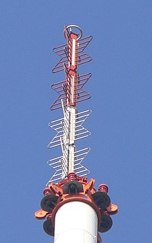
A VHF television broadcasting antenna. This is a common type called a super turnstile or batwing antenna.

VHF is the first band at which wavelengths are small enough that efficient transmitting antennas are short enough to mount on vehicles and handheld devices, a quarter wave whip antenna at VHF frequencies is 25 cm to 2.5 meter (10 inches to 8 feet) long. So the VHF and UHF wavelengths are used for two-way radios in vehicles, aircraft, and handheld transceivers and walkie-talkies. Portable radios usually use whips or rubber ducky antennas, while base stations usually use larger fiberglass whips or collinear arrays of vertical dipoles.

For directional antennas, the Yagi antenna is the most widely used as a high gain or "beam" antenna. For television reception, the Yagi is used, as well as the log-periodic antenna due to its wider bandwidth. Helical and turnstile antennas are used for satellite communication since they employ circular polarization. For even higher gain, multiple Yagis or helicals can be mounted together to make array antennas. Vertical collinear arrays of dipoles can be used to make high gain omnidirectional antennas, in which more of the antenna's power is radiated in horizontal directions. Television and FM broadcasting stations use collinear arrays of specialized dipole antennas such as batwing antennas.

Universal use

Certain subparts of the VHF band have the same use around the world. Some national uses are detailed below.

By country

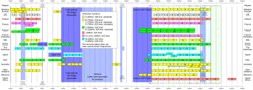
A plan showing VHF use in television, FM radio, amateur radio, marine radio and aviation.

Australia

The VHF TV band in Australia was originally allocated channels 1 to 10-with channels 2, 7 and 9 assigned for the initial services in Sydney and Melbourne, and later the same channels were assigned in Brisbane, Adelaide and Perth. Other capital cities and regional areas used a combination of these and other frequencies as available. The initial commercial services in Hobart and Darwin were respectively allocated channels 6 and 8 rather than 7 or 9.

By the early 1960s it became apparent that the 10 VHF channels were insufficient to support the growth of television services. This was rectified by the addition of three additional frequencies-channels 0, 5A and 11. Older television sets using rotary dial tuners required adjustment to receive these new channels. Most TVs of that era were not equipped to receive these broadcasts, and so were modified at the owners' expense to be able to tune into these bands; otherwise the owner had to buy a new TV.

Several TV stations were allocated to VHF channels 3, 4 and 5, which were within the FM radio bands although not yet used for that purpose. A couple of notable examples were NBN-3 Newcastle, WIN-4 Wollongong and ABC Newcastle on channel 5. While some Channel 5 stations were moved to 5A in the 1970s and 80s, beginning in the 1990s, the Australian Broadcasting Authority began a process to move these stations to UHF bands to free up valuable VHF spectrum for its original purpose of FM radio. In addition, by 1985 the federal government decided new TV stations are to be broadcast on the UHF band.

Two new VHF channels, 9A and 12, have since been made available and are being used primarily for digital services (e.g. ABC in capital cities) but also for some new analogue services in regional areas. Because channel 9A is not used for television services in or near Sydney, Melbourne, Brisbane, Adelaide or Perth, digital radio in those cities are broadcast on DAB frequencies blocks 9A, 9B and 9C.

VHF radio is also used for marine Radio as per its long-distance reachability comparing UHF frequencies.

Example allocation of VHF–UHF frequencies:

  • Radionavigation 60: 84–86 MHz
  • Fixed Maritime Mobile: 130–135.7 MHz
  • Fixed Aeronautical radio navigation: 160–190 MHz
  • Broadcasting Aeronautical Radionavigation: 255–283.5 MHz
  • Aeronautical Radionavigation AUS 49 / Maritime Radionavigation (radiobeacons) 73: 315–325 MHz

New Zealand

Until 2013, the four main free-to-air TV stations in New Zealand used the VHF television bands (Band I and Band III) to transmit to New Zealand households. Other stations, including a variety of pay and regional free-to-air stations, were forced to broadcast in the UHF band, since the VHF band had been very overloaded with four stations sharing a very small frequency band, which was so overcrowded that one or more channels would not be available in some smaller towns.

However, at the end of 2013, all television channels stopped broadcasting on the VHF bands, as New Zealand moved to digital television broadcasting, requiring all stations to either broadcast on UHF or satellite (where UHF was unavailable) utilising the Freeview service.

Refer to Australasian television frequencies for more information.

United Kingdom

British television originally used VHF band I and band III. Television on VHF was in black and white with 405-line format (although there were experiments with all three colour systems-NTSC, PAL, and SECAM-adapted for the 405-line system in the late 1950s and early 1960s).

British colour television was broadcast on UHF (channels 21–69), beginning in the late 1960s. From then on, TV was broadcast on both VHF and UHF (VHF being a monochromatic downconversion from the 625-line colour signal), with the exception of BBC2 (which had always broadcast solely on UHF). The last British VHF TV transmitters closed down on January 3, 1985. VHF band III is now used in the UK for digital audio broadcasting, and VHF band II is used for FM radio, as it is in most of the world.

Unusually, the UK has an amateur radio allocation at 4 metres, 70–70.5 MHz.

United States and Canada

Frequency assignments between US and Canadian users are closely coordinated since much of the Canadian population is within VHF radio range of the US border. Certain discrete frequencies are reserved for radio astronomy. The general services in the VHF band are:

  • 30–49.6 MHz: Licensed 2-way land mobile communication, with various sub-bands.
  • 30–88 MHz: Military VHF FM, including SINCGARS
  • 43–50 MHz: Cordless telephones, 49 MHz FM walkie-talkies and radio controlled toys, and mixed 2-way mobile communication. The FM broadcast band originally operated here (42–50 MHz) before it was moved to 88–108 MHz.
  • 50–54 MHz: Amateur radio 6-meter band
  • 54–88 MHz, known as "Band I" internationally; some DTV stations will appear here. See Pan-American television frequencies.
    • 54–72 MHz TV channels 2–4 (VHF-Lo)
    • 72–76 MHz: Radio controlled models, industrial remote control, and other devices. Model aircraft operate on 72 MHz while surface models operate on 75 MHz in the US and Canada, air navigation beacons 74.8–75.2 MHz.
    • 76–88 MHz TV channels 5–6 (VHF-Lo)
  • 87.5–108 MHz: FM radio broadcasting (87.9–91.9 non-commercial, 92–108 commercial in the United States) (known as "Band II" internationally)
  • 108–118 MHz: Air navigation beacons VOR
  • 118–137 MHz: Airband for air traffic control, AM
    • 121.5 MHz is an emergency frequency
  • 137–138 MHz Space research, space operations, meteorological satellite
  • 138–144 MHz: Land mobile, auxiliary civil services, satellite, space research, and other miscellaneous services
  • 144–148 MHz: Amateur radio 2-meter band
  • 148–150 MHz: Land mobile, fixed, satellite
  • 150–156 MHz: "VHF business band," public safety, the unlicensed Multi-Use Radio Service (MURS), and other 2-way land mobile, FM
  • 156–158 MHz VHF Marine Radio
    • 156.8 MHz (Channel 16) is the maritime emergency and contact frequency.
  • 159.81-161.565 MHz railways 
    • 159.81–160.2 are railroads in Canada only and is used by trucking companies in the U.S.
  • 160.6–162 Wireless microphones and TV/FM broadcast remote pickup
  • 162.4–162.55: NOAA Weather Stations, narrowband FM, Weatheradio Canada Stations
  • 174–240 MHz, known as "Band III" internationally. A number of DTV channels have begun broadcasting here, especially many of the stations which were assigned to these channels for previous analog operation.
    • 174–216 MHz television channels 7–13 (VHF-Hi)
    • 174–216 MHz: professional wireless microphones (low power, certain exact frequencies only)
    • 216–222 MHz: land mobile, fixed, maritime mobile,
    • 222–225 MHz: 1.25 meters (US) (Canada 219–220, 222–225 MHz) amateur radio
  • 225 MHz and above (UHF): Military aircraft radio, 243 MHz is an emergency frequency (225–400 MHz) AM, including HAVE QUICK, dGPS RTCM-104

Cable television, though not transmitted aerially, uses a spectrum of frequencies overlapping VHF.

VHF television

The U.S. FCC allocated television broadcasting to a channelized roster as early as 1938 with 19 channels. That changed three more times: in 1940 when Channel 19 was deleted and several channels changed frequencies, then in 1946 with television going from 18 channels to 13 channels, again with different frequencies, and finally in 1948 with the removal of Channel 1 (analog channels 2–13 remain as they were, even on cable television). Channels 14–19 later appeared on the UHF band, while channel 1 remains unused.

87.5–87.9 MHz

87.5–87.9 MHz is a radio frequency which, in most of the world, is used for FM broadcasting. In North America, however, this bandwidth is allocated to VHF television channel 6 (82–88 MHz). The analog audio for TV channel 6 is broadcast at 87.75 MHz (adjustable down to 87.74). Several stations, known as Frankenstations, most notably those joining the Pulse 87 franchise, have operated on this frequency as radio stations, though they use television licenses. As a result, FM radio receivers such as those found in automobiles which are designed to tune into this frequency range could receive the audio for analog-mode programming on the local TV channel 6 while in North America. The practice largely ended with the DTV transition in 2009, although some still exist.

The FM broadcast channel at 87.9 MHz is normally off-limits for FM audio broadcasting; it is reserved for displaced class D stations which have no other frequencies in the normal 88.1–107.9 MHz subband to move to. So far, only two stations have qualified to operate on 87.9 MHz: 10–watt KSFH in Mountain View, California and 34–watt translator K200AA in Sun Valley, Nevada.

Unlicensed operation

In some countries, particularly the United States and Canada, limited low-power license-free operation is available in the FM broadcast band for purposes such as micro-broadcasting and sending output from CD or digital media players to radios without auxiliary-in jacks, though this is illegal in some other countries. This practice was legalised in the United Kingdom on 8 December 2006.

Fearmongering

From Wikipedia, the free encyclopedia https://en.wikipedia.org/wiki/Fearmongering Fearmongering ,...