Search This Blog

Friday, August 11, 2023

Chemical vapor deposition

From Wikipedia, the free encyclopedia
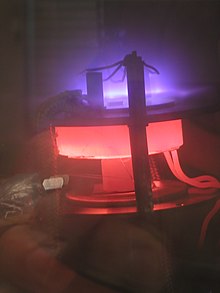
DC plasma (violet) enhances the growth of carbon nanotubes in a laboratory-scale PECVD (plasma-enhanced chemical vapor deposition) apparatus

Chemical vapor deposition (CVD) is a vacuum deposition method used to produce high-quality, and high-performance, solid materials. The process is often used in the semiconductor industry to produce thin films.

In typical CVD, the wafer (substrate) is exposed to one or more volatile precursors, which react and/or decompose on the substrate surface to produce the desired deposit. Frequently, volatile by-products are also produced, which are removed by gas flow through the reaction chamber.

Microfabrication processes widely use CVD to deposit materials in various forms, including: monocrystalline, polycrystalline, amorphous, and epitaxial. These materials include: silicon (dioxide, carbide, nitride, oxynitride), carbon (fiber, nanofibers, nanotubes, diamond and graphene), fluorocarbons, filaments, tungsten, titanium nitride and various high-κ dielectrics.

The term chemical vapour deposition was coined 1960 by John M. Blocher, Jr. who intended to differentiate chemical from physical vapour deposition (PVD).

Types

Hot-wall thermal CVD (batch operation type)
 
Plasma assisted CVD

CVD is practiced in a variety of formats. These processes generally differ in the means by which chemical reactions are initiated.

  • Classified by operating conditions:
    • Atmospheric pressure CVD (APCVD) – CVD at atmospheric pressure.
    • Low-pressure CVD (LPCVD) – CVD at sub-atmospheric pressures. Reduced pressures tend to reduce unwanted gas-phase reactions and improve film uniformity across the wafer.
    • Ultrahigh vacuum CVD (UHVCVD) – CVD at very low pressure, typically below 10−6 Pa (≈ 10−8 torr). Note that in other fields, a lower division between high and ultra-high vacuum is common, often 10−7 Pa.
    • Sub-atmospheric CVD (SACVD) – CVD at sub-atmospheric pressures. Uses tetraethyl orthosilicate (TEOS) and ozone to fill high aspect ratio Si structures with silicon dioxide (SiO2).

Most modern CVD is either LPCVD or UHVCVD.

  • Classified by physical characteristics of vapor:
    • Aerosol assisted CVD (AACVD) – CVD in which the precursors are transported to the substrate by means of a liquid/gas aerosol, which can be generated ultrasonically. This technique is suitable for use with non-volatile precursors.
    • Direct liquid injection CVD (DLICVD) – CVD in which the precursors are in liquid form (liquid or solid dissolved in a convenient solvent). Liquid solutions are injected in a vaporization chamber towards injectors (typically car injectors). The precursor vapors are then transported to the substrate as in classical CVD. This technique is suitable for use on liquid or solid precursors. High growth rates can be reached using this technique.
  • Classified by type of substrate heating:
    • Hot wall CVD – CVD in which the chamber is heated by an external power source and the substrate is heated by radiation from the heated chamber walls.
    • Cold wall CVD – CVD in which only the substrate is directly heated either by induction or by passing current through the substrate itself or a heater in contact with the substrate. The chamber walls are at room temperature.
  • Plasma methods (see also Plasma processing):
    • Microwave plasma-assisted CVD (MPCVD)
    • Plasma-enhanced CVD (PECVD) – CVD that utilizes plasma to enhance chemical reaction rates of the precursors. PECVD processing allows deposition at lower temperatures, which is often critical in the manufacture of semiconductors. The lower temperatures also allow for the deposition of organic coatings, such as plasma polymers, that have been used for nanoparticle surface functionalization.
    • Remote plasma-enhanced CVD (RPECVD) – Similar to PECVD except that the wafer substrate is not directly in the plasma discharge region. Removing the wafer from the plasma region allows processing temperatures down to room temperature.
    • Low-energy plasma-enhanced chemical vapor deposition (LEPECVD) - CVD employing a high density, low energy plasma to obtain epitaxial deposition of semiconductor materials at high rates and low temperatures.
  • Atomic-layer CVD (ALCVD) – Deposits successive layers of different substances to produce layered, crystalline films. See Atomic layer epitaxy.
  • Combustion chemical vapor deposition (CCVD) – Combustion Chemical Vapor Deposition or flame pyrolysis is an open-atmosphere, flame-based technique for depositing high-quality thin films and nanomaterials.
  • Hot filament CVD (HFCVD) – also known as catalytic CVD (Cat-CVD) or more commonly, initiated CVD, this process uses a hot filament to chemically decompose the source gases. The filament temperature and substrate temperature thus are independently controlled, allowing colder temperatures for better absorption rates at the substrate and higher temperatures necessary for decomposition of precursors to free radicals at the filament.
  • Hybrid physical-chemical vapor deposition (HPCVD) – This process involves both chemical decomposition of precursor gas and vaporization of a solid source.
  • Metalorganic chemical vapor deposition (MOCVD) – This CVD process is based on metalorganic precursors.
  • Rapid thermal CVD (RTCVD) – This CVD process uses heating lamps or other methods to rapidly heat the wafer substrate. Heating only the substrate rather than the gas or chamber walls helps reduce unwanted gas-phase reactions that can lead to particle formation.
  • Vapor-phase epitaxy (VPE)
  • Photo-initiated CVD (PICVD) – This process uses UV light to stimulate chemical reactions. It is similar to plasma processing, given that plasmas are strong emitters of UV radiation. Under certain conditions, PICVD can be operated at or near atmospheric pressure.
  • Laser chemical vapor deposition (LCVD) - This CVD process uses lasers to heat spots or lines on a substrate in semiconductor applications. In MEMS and in fiber production the lasers are used rapidly to break down the precursor gas—process temperature can exceed 2000 °C—to build up a solid structure in much the same way as laser sintering based 3-D printers build up solids from powders.

Uses

CVD is commonly used to deposit conformal films and augment substrate surfaces in ways that more traditional surface modification techniques are not capable of. CVD is extremely useful in the process of atomic layer deposition at depositing extremely thin layers of material. A variety of applications for such films exist. Gallium arsenide is used in some integrated circuits (ICs) and photovoltaic devices. Amorphous polysilicon is used in photovoltaic devices. Certain carbides and nitrides confer wear-resistance. Polymerization by CVD, perhaps the most versatile of all applications, allows for super-thin coatings which possess some very desirable qualities, such as lubricity, hydrophobicity and weather-resistance to name a few. The CVD of metal-organic frameworks, a class of crystalline nanoporous materials, has recently been demonstrated. Recently scaled up as an integrated cleanroom process depositing large-area substrates, the applications for these films are anticipated in gas sensing and low-κ dielectrics. CVD techniques are advantageous for membrane coatings as well, such as those in desalination or water treatment, as these coatings can be sufficiently uniform (conformal) and thin that they do not clog membrane pores.

Commercially important materials prepared by CVD

Polysilicon

Polycrystalline silicon is deposited from trichlorosilane (SiHCl3) or silane (SiH4), using the following reactions:

SiHCl3 → Si + Cl2 + HCl
SiH4 → Si + 2 H2

This reaction is usually performed in LPCVD systems, with either pure silane feedstock, or a solution of silane with 70–80% nitrogen. Temperatures between 600 and 650 °C and pressures between 25 and 150 Pa yield a growth rate between 10 and 20 nm per minute. An alternative process uses a hydrogen-based solution. The hydrogen reduces the growth rate, but the temperature is raised to 850 or even 1050 °C to compensate. Polysilicon may be grown directly with doping, if gases such as phosphine, arsine or diborane are added to the CVD chamber. Diborane increases the growth rate, but arsine and phosphine decrease it.

Silicon dioxide

Silicon dioxide (usually called simply "oxide" in the semiconductor industry) may be deposited by several different processes. Common source gases include silane and oxygen, dichlorosilane (SiCl2H2) and nitrous oxide (N2O), or tetraethylorthosilicate (TEOS; Si(OC2H5)4). The reactions are as follows:

SiH4 + O2 → SiO2 + 2 H2
SiCl2H2 + 2 N2O → SiO2 + 2 N2 + 2 HCl
Si(OC2H5)4 → SiO2 + byproducts

The choice of source gas depends on the thermal stability of the substrate; for instance, aluminium is sensitive to high temperature. Silane deposits between 300 and 500 °C, dichlorosilane at around 900 °C, and TEOS between 650 and 750 °C, resulting in a layer of low- temperature oxide (LTO). However, silane produces a lower-quality oxide than the other methods (lower dielectric strength, for instance), and it deposits nonconformally. Any of these reactions may be used in LPCVD, but the silane reaction is also done in APCVD. CVD oxide invariably has lower quality than thermal oxide, but thermal oxidation can only be used in the earliest stages of IC manufacturing.

Oxide may also be grown with impurities (alloying or "doping"). This may have two purposes. During further process steps that occur at high temperature, the impurities may diffuse from the oxide into adjacent layers (most notably silicon) and dope them. Oxides containing 5–15% impurities by mass are often used for this purpose. In addition, silicon dioxide alloyed with phosphorus pentoxide ("P-glass") can be used to smooth out uneven surfaces. P-glass softens and reflows at temperatures above 1000 °C. This process requires a phosphorus concentration of at least 6%, but concentrations above 8% can corrode aluminium. Phosphorus is deposited from phosphine gas and oxygen:

4 PH3 + 5 O2 → 2 P2O5 + 6 H2

Glasses containing both boron and phosphorus (borophosphosilicate glass, BPSG) undergo viscous flow at lower temperatures; around 850 °C is achievable with glasses containing around 5 weight % of both constituents, but stability in air can be difficult to achieve. Phosphorus oxide in high concentrations interacts with ambient moisture to produce phosphoric acid. Crystals of BPO4 can also precipitate from the flowing glass on cooling; these crystals are not readily etched in the standard reactive plasmas used to pattern oxides, and will result in circuit defects in integrated circuit manufacturing.

Besides these intentional impurities, CVD oxide may contain byproducts of the deposition. TEOS produces a relatively pure oxide, whereas silane introduces hydrogen impurities, and dichlorosilane introduces chlorine.

Lower temperature deposition of silicon dioxide and doped glasses from TEOS using ozone rather than oxygen has also been explored (350 to 500 °C). Ozone glasses have excellent conformality but tend to be hygroscopic – that is, they absorb water from the air due to the incorporation of silanol (Si-OH) in the glass. Infrared spectroscopy and mechanical strain as a function of temperature are valuable diagnostic tools for diagnosing such problems.

Silicon nitride

Silicon nitride is often used as an insulator and chemical barrier in manufacturing ICs. The following two reactions deposit silicon nitride from the gas phase:

3 SiH4 + 4 NH3 → Si3N4 + 12 H2
3 SiCl2H2 + 4 NH3 → Si3N4 + 6 HCl + 6 H2

Silicon nitride deposited by LPCVD contains up to 8% hydrogen. It also experiences strong tensile stress, which may crack films thicker than 200 nm. However, it has higher resistivity and dielectric strength than most insulators commonly available in microfabrication (1016 Ω·cm and 10 MV/cm, respectively).

Another two reactions may be used in plasma to deposit SiNH:

2 SiH4 + N2 → 2 SiNH + 3 H2
SiH4 + NH3 → SiNH + 3 H2

These films have much less tensile stress, but worse electrical properties (resistivity 106 to 1015 Ω·cm, and dielectric strength 1 to 5 MV/cm).

Metals

Tungsten CVD, used for forming conductive contacts, vias, and plugs on a semiconductor device, is achieved from tungsten hexafluoride (WF6), which may be deposited in two ways:

WF6 → W + 3 F2
WF6 + 3 H2 → W + 6 HF

Other metals, notably aluminium and copper, can be deposited by CVD. As of 2010, commercially cost-effective CVD for copper did not exist, although volatile sources exist, such as Cu(hfac)2. Copper is typically deposited by electroplating. Aluminium can be deposited from triisobutylaluminium (TIBAL) and related organoaluminium compounds.

CVD for molybdenum, tantalum, titanium, nickel is widely used. These metals can form useful silicides when deposited onto silicon. Mo, Ta and Ti are deposited by LPCVD, from their pentachlorides. Nickel, molybdenum, and tungsten can be deposited at low temperatures from their carbonyl precursors. In general, for an arbitrary metal M, the chloride deposition reaction is as follows:

2 MCl5 + 5 H2 → 2 M + 10 HCl

whereas the carbonyl decomposition reaction can happen spontaneously under thermal treatment or acoustic cavitation and is as follows:

M(CO)n → M + n CO

the decomposition of metal carbonyls is often violently precipitated by moisture or air, where oxygen reacts with the metal precursor to form metal or metal oxide along with carbon dioxide.

Niobium(V) oxide layers can be produced by the thermal decomposition of niobium(V) ethoxide with the loss of diethyl ether according to the equation:

2 Nb(OC2H5)5 → Nb2O5 + 5 C2H5OC2H5

Graphene

Many variations of CVD can be utilized to synthesize graphene. Although many advancements have been made, the processes listed below are not commercially viable yet.

  • Carbon source

The most popular carbon source that is used to produce graphene is methane gas. One of the less popular choices is petroleum asphalt, notable for being inexpensive but more difficult to work with.

Although methane is the most popular carbon source, hydrogen is required during the preparation process to promote carbon deposition on the substrate. If the flow ratio of methane and hydrogen are not appropriate, it will cause undesirable results. During the growth of graphene, the role of methane is to provide a carbon source, the role of hydrogen is to provide H atoms to corrode amorphous C, and improve the quality of graphene. But excessive H atoms can also corrode graphene. As a result, the integrity of the crystal lattice is destroyed, and the quality of graphene is deteriorated. Therefore, by optimizing the flow rate of methane and hydrogen gases in the growth process, the quality of graphene can be improved.

  • Use of catalyst

The use of catalyst is viable in changing the physical process of graphene production. Notable examples include iron nanoparticles, nickel foam, and gallium vapor. These catalysts can either be used in situ during graphene buildup or situated at some distance away at the deposition area. Some catalysts require another step to remove them from the sample material.

The direct growth of high-quality, large single-crystalline domains of graphene on a dielectric substrate is of vital importance for applications in electronics and optoelectronics. Combining the advantages of both catalytic CVD and the ultra-flat dielectric substrate, gaseous catalyst-assisted CVD paves the way for synthesizing high-quality graphene for device applications while avoiding the transfer process.

  • Physical conditions

Physical conditions such as surrounding pressure, temperature, carrier gas, and chamber material play a big role in production of graphene.

Most systems use LPCVD with pressures ranging from 1 to 1500 Pa. However, some still use APCVD. Low pressures are used more commonly as they help prevent unwanted reactions and produce more uniform thickness of deposition on the substrate.

On the other hand, temperatures used range from 800–1050 °C. High temperatures translate to an increase of the rate of reaction. Caution has to be exercised as high temperatures do pose higher danger levels in addition to greater energy costs.

  • Carrier gas

Hydrogen gas and inert gases such as argon are flowed into the system. These gases act as a carrier, enhancing surface reaction and improving reaction rate, thereby increasing deposition of graphene onto the substrate.

  • Chamber material

Standard quartz tubing and chambers are used in CVD of graphene. Quartz is chosen because it has a very high melting point and is chemically inert. In other words, quartz does not interfere with any physical or chemical reactions regardless of the conditions.

  • Methods of analysis of results

Raman spectroscopy, X-ray spectroscopy, transmission electron microscopy (TEM), and scanning electron microscopy (SEM) are used to examine and characterize the graphene samples.

Raman spectroscopy is used to characterize and identify the graphene particles; X-ray spectroscopy is used to characterize chemical states; TEM is used to provide fine details regarding the internal composition of graphene; SEM is used to examine the surface and topography.

Sometimes, atomic force microscopy (AFM) is used to measure local properties such as friction and magnetism.

Cold wall CVD technique can be used to study the underlying surface science involved in graphene nucleation and growth as it allows unprecedented control of process parameters like gas flow rates, temperature and pressure as demonstrated in a recent study. The study was carried out in a home-built vertical cold wall system utilizing resistive heating by passing direct current through the substrate. It provided conclusive insight into a typical surface-mediated nucleation and growth mechanism involved in two-dimensional materials grown using catalytic CVD under conditions sought out in the semiconductor industry.

Graphene nanoribbon

In spite of graphene's exciting electronic and thermal properties, it is unsuitable as a transistor for future digital devices, due to the absence of a bandgap between the conduction and valence bands. This makes it impossible to switch between on and off states with respect to electron flow. Scaling things down, graphene nanoribbons of less than 10 nm in width do exhibit electronic bandgaps and are therefore potential candidates for digital devices. Precise control over their dimensions, and hence electronic properties, however, represents a challenging goal, and the ribbons typically possess rough edges that are detrimental to their performance.

Diamond
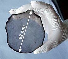
Free-standing single-crystal CVD diamond disc
A colorless faceted gem
Colorless gem cut from diamond grown by chemical vapor deposition

CVD can be used to produce a synthetic diamond by creating the circumstances necessary for carbon atoms in a gas to settle on a substrate in crystalline form. CVD of diamonds has received much attention in the materials sciences because it allows many new applications that had previously been considered too expensive. CVD diamond growth typically occurs under low pressure (1–27 kPa; 0.145–3.926 psi; 7.5–203 Torr) and involves feeding varying amounts of gases into a chamber, energizing them and providing conditions for diamond growth on the substrate. The gases always include a carbon source, and typically include hydrogen as well, though the amounts used vary greatly depending on the type of diamond being grown. Energy sources include hot filament, microwave power, and arc discharges, among others. The energy source is intended to generate a plasma in which the gases are broken down and more complex chemistries occur. The actual chemical process for diamond growth is still under study and is complicated by the very wide variety of diamond growth processes used.

Using CVD, films of diamond can be grown over large areas of substrate with control over the properties of the diamond produced. In the past, when high pressure high temperature (HPHT) techniques were used to produce a diamond, the result was typically very small free-standing diamonds of varying sizes. With CVD diamond, growth areas of greater than fifteen centimeters (six inches) in diameter have been achieved, and much larger areas are likely to be successfully coated with diamond in the future. Improving this process is key to enabling several important applications.

The growth of diamond directly on a substrate allows the addition of many of diamond's important qualities to other materials. Since diamond has the highest thermal conductivity of any bulk material, layering diamond onto high heat-producing electronics (such as optics and transistors) allows the diamond to be used as a heat sink. Diamond films are being grown on valve rings, cutting tools, and other objects that benefit from diamond's hardness and exceedingly low wear rate. In each case the diamond growth must be carefully done to achieve the necessary adhesion onto the substrate. Diamond's very high scratch resistance and thermal conductivity, combined with a lower coefficient of thermal expansion than Pyrex glass, a coefficient of friction close to that of Teflon (polytetrafluoroethylene) and strong lipophilicity would make it a nearly ideal non-stick coating for cookware if large substrate areas could be coated economically.

CVD growth allows one to control the properties of the diamond produced. In the area of diamond growth, the word "diamond" is used as a description of any material primarily made up of sp3-bonded carbon, and there are many different types of diamond included in this. By regulating the processing parameters—especially the gases introduced, but also including the pressure the system is operated under, the temperature of the diamond, and the method of generating plasma—many different materials that can be considered diamond can be made. Single-crystal diamond can be made containing various dopants. Polycrystalline diamond consisting of grain sizes from several nanometers to several micrometers can be grown. Some polycrystalline diamond grains are surrounded by thin, non-diamond carbon, while others are not. These different factors affect the diamond's hardness, smoothness, conductivity, optical properties and more.
Chalcogenides

Commercially, mercury cadmium telluride is of continuing interest for detection of infrared radiation. Consisting of an alloy of CdTe and HgTe, this material can be prepared from the dimethyl derivatives of the respective elements.

Overhead power line

From Wikipedia, the free encyclopedia
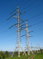
320 and 150 kV in Dnipro

An overhead power line is a structure used in electric power transmission and distribution to transmit electrical energy across long distances. It consists of one or more uninsulated electrical cables (commonly multiples of three for three-phase power) suspended by towers or poles.

Since most of the insulation is provided by the surrounding air, overhead power lines are generally the least costly method of power transmission for large quantities of electric energy.

Construction

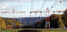
Overhead powerline Dnieper crossing, Ukraine

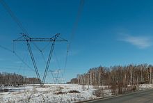
Towers for support of the lines are made of wood either grown or laminated, steel or aluminum (either lattice structures or tubular poles), concrete, and occasionally reinforced plastics. The bare wire conductors on the line are generally made of aluminum (either plain or reinforced with steel or composite materials such as carbon and glass fiber), though some copper wires are used in medium-voltage distribution and low-voltage connections to customer premises. A major goal of overhead power line design is to maintain adequate clearance between energized conductors and the ground so as to prevent dangerous contact with the line, and to provide reliable support for the conductors, resilience to storms, ice loads, earthquakes and other potential damage causes. Today overhead lines are routinely operated at voltages exceeding 765,000 volts between conductors.

Classification of transmission lines

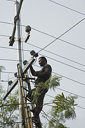
A man working on powerlines in Nauru (2007)

By operating voltage

Overhead power transmission lines are classified in the electrical power industry by the range of voltages:

  • Low voltage (LV), less than 1000 volts, used for connection between a residential or small commercial customer and the utility.
  • Medium voltage (MV; distribution), between 1000 volts (1 kV) and 69 kV, used for distribution in urban and rural areas.
  • High voltage (HV; subtransmission less than 100 kV; subtransmission or transmission at voltages such as 115 kV and 138 kV), used for sub-transmission and transmission of bulk quantities of electric power and connection to very large consumers.
  • Extra high voltage (EHV; transmission) – from 345 kV, up to about 800 kV, used for long distance, very high power transmission.
  • Ultra high voltage (UHV), often associated with ≥ ±800 kVDC and ≥ 1000 kVAC

By length of the line

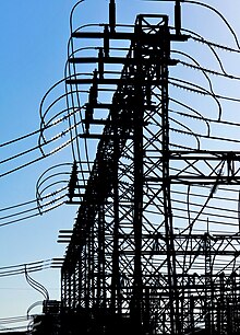
430 and 250 kV at medium substation

The overhead transmission line is generally categorized into three classes, depending on the length of the line:

  • Lines shorter than 50 km are generally referred to as short transmission lines.
  • Lines between 50 km and 150 km are generally referred to as medium transmission lines.
  • Lines longer than 150 km are considered long transmission lines.

This categorization is mainly done for the ease of performance analysis of transmission lines by power engineers.

Structures

Tubular transmission tower
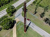
Tubular transmission tower near Galesville, Wisconsin
End of line of T-pylons

Structures for overhead lines take a variety of shapes depending on the type of line. Structures may be as simple as wood poles directly set in the earth, carrying one or more cross-arm beams to support conductors, or "armless" construction with conductors supported on insulators attached to the side of the pole. Tubular steel poles are typically used in urban areas. High-voltage lines are often carried on lattice-type steel towers or pylons. For remote areas, aluminum towers may be placed by helicopters. Concrete poles have also been used. Poles made of reinforced plastics are also available, but their high cost restricts application.

Each structure must be designed for the loads imposed on it by the conductors. The weight of the conductor must be supported, as well as dynamic loads due to wind and ice accumulation, and effects of vibration. Where conductors are in a straight line, towers need only resist the weight since the tension in the conductors approximately balances with no resultant force on the structure. Flexible conductors supported at their ends approximate the form of a catenary, and much of the analysis for construction of transmission lines relies on the properties of this form.

A large transmission line project may have several types of towers, with "tangent" ("suspension" or "line" towers, UK) towers intended for most positions and more heavily constructed towers used for turning the line through an angle, dead-ending (terminating) a line, or for important river or road crossings. Depending on the design criteria for a particular line, semi-flexible type structures may rely on the weight of the conductors to be balanced on both sides of each tower. More rigid structures may be intended to remain standing even if one or more conductors is broken. Such structures may be installed at intervals in power lines to limit the scale of cascading tower failures.

Foundations for tower structures may be large and costly, particularly if the ground conditions are poor, such as in wetlands. Each structure may be stabilized considerably by the use of guy wires to counteract some of the forces applied by the conductors.

Low-profile power lines near an airfield

Power lines and supporting structures can be a form of visual pollution. In some cases the lines are buried to avoid this, but this "undergrounding" is more expensive and therefore not common.

For a single wood utility pole structure, a pole is placed in the ground, then three crossarms extend from this, either staggered or all to one side. The insulators are attached to the crossarms. For an "H"-type wood pole structure, two poles are placed in the ground, then a crossbar is placed on top of these, extending to both sides. The insulators are attached at the ends and in the middle. Lattice tower structures have two common forms. One has a pyramidal base, then a vertical section, where three crossarms extend out, typically staggered. The strain insulators are attached to the crossarms. Another has a pyramidal base, which extends to four support points. On top of this a horizontal truss-like structure is placed.

A grounded wire is sometimes strung along the tops of the towers to provide lightning protection. An optical ground wire is a more advanced version with embedded optical fibers for communication. Overhead wire markers can be mounted on the ground wire to meet International Civil Aviation Organization recommendations. Some markers include flashing lamps for night-time warning.

Circuits

A single-circuit transmission line carries conductors for only one circuit. For a three-phase system, this implies that each tower supports three conductors.

A double-circuit transmission line has two circuits. For three-phase systems, each tower supports and insulates six conductors. Single phase AC-power lines as used for traction current have four conductors for two circuits. Usually both circuits operate at the same voltage.

In HVDC systems typically two conductors are carried per line, but in rare cases only one pole of the system is carried on a set of towers.

In some countries, such as Germany, most power lines with voltages above 100 kV are implemented as double, quadruple or in rare cases even hextuple power line as rights of way are rare. Sometimes all conductors are installed with the erection of the pylons; often some circuits are installed later. A disadvantage of double circuit transmission lines is that maintenance can be difficult, as either work in close proximity of high voltage or switch-off of two circuits is required. In case of failure, both systems can be affected.

Insulators

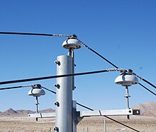
Medium-voltage power lines with ceramic insulators in California
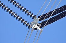
Modular suspension insulators are used for high-voltage lines. The objects attached to the conductors near the bottom of the insulator are Stockbridge dampers.

Insulators must support the conductors and withstand both the normal operating voltage and surges due to switching and lightning. Insulators are broadly classified as either pin-type, which support the conductor above the structure, or suspension type, where the conductor hangs below the structure. The invention of the strain insulator was a critical factor in allowing higher voltages to be used.

At the end of the 19th century, the limited electrical strength of telegraph-style pin insulators limited the voltage to no more than 69,000 volts. Up to about 33 kV (69 kV in North America) both types are commonly used. At higher voltages only suspension-type insulators are common for overhead conductors.

Insulators are usually made of wet-process porcelain or toughened glass, with increasing use of glass-reinforced polymer insulators. However, with rising voltage levels, polymer insulators (silicone rubber based) are seeing increasing usage. China has already developed polymer insulators having a highest system voltage of 1100 kV and India is currently developing a 1200 kV (highest system voltage) line which will initially be charged with 400 kV to be upgraded to a 1200 kV line.

Suspension insulators are made of multiple units, with the number of unit insulator disks increasing at higher voltages. The number of disks is chosen based on line voltage, lightning withstand requirement, altitude, and environmental factors such as fog, pollution, or salt spray. In cases where these conditions are suboptimal, longer insulators must be used. Longer insulators with longer creepage distance for leakage current, are required in these cases. Strain insulators must be strong enough mechanically to support the full weight of the span of conductor, as well as loads due to ice accumulation, and wind.

Porcelain insulators may have a semi-conductive glaze finish, so that a small current (a few milliamperes) passes through the insulator. This warms the surface slightly and reduces the effect of fog and dirt accumulation. The semiconducting glaze also ensures a more even distribution of voltage along the length of the chain of insulator units.

Polymer insulators by nature have hydrophobic characteristics providing for improved wet performance. Also, studies have shown that the specific creepage distance required in polymer insulators is much lower than that required in porcelain or glass. Additionally, the mass of polymer insulators (especially in higher voltages) is approximately 50% to 30% less than that of a comparative porcelain or glass string. Better pollution and wet performance is leading to the increased use of such insulators.

Insulators for very high voltages, exceeding 200 kV, may have grading rings installed at their terminals. This improves the electric field distribution around the insulator and makes it more resistant to flash-over during voltage surges.

Conductors

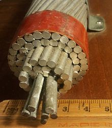
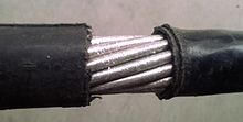
Sample cross-section of ACSR power line

The most common conductor in use for transmission today is aluminum conductor steel reinforced (ACSR). Also seeing much use is all-aluminum-alloy conductor (AAAC). Aluminum is used because it has about half the weight and lower cost of a comparable resistance copper cable. It does, however, require a larger diameter than copper because of lower specific conductivity. Copper was more popular in the past and is still in use, especially at lower voltages and for grounding.

While larger conductors lose less energy because of their lower electrical resistance, they cost more than smaller conductors. An optimization rule called Kelvin's Law states that the optimum size of conductor for a line is found when the cost of the energy wasted in a smaller conductor is equal to the annual interest paid on that additional cost of the line construction for a larger conductor. The optimization problem is made more complex by additional factors such as varying annual load, varying cost of installation, and the discrete sizes of cable that are commonly made.

Since a conductor is a flexible object with uniform weight per unit length, the shape of a conductor hanging between two towers approximates that of a catenary. The sag of the conductor (vertical distance between the highest and lowest point of the curve) varies depending on the temperature and additional load such as ice cover. A minimum overhead clearance must be maintained for safety. Since the length of the conductor increases with increasing heat produced by the current through it, it is sometimes possible to increase the power handling capacity (uprate) by changing the conductors for a type with a lower coefficient of thermal expansion or a higher allowable operating temperature.

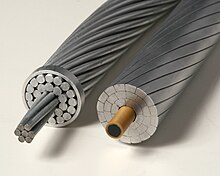
Conventional ACSR (left) and modern carbon core (right) conductors

Two such conductors that offer reduced thermal sag are known as composite core conductors (ACCR and ACCC conductor). In lieu of steel core strands that are often used to increase overall conductor strength, the ACCC conductor uses a carbon and glass fiber core that offers a coefficient of thermal expansion about 1/10 of that of steel. While the composite core is nonconductive, it is substantially lighter and stronger than steel, which allows the incorporation of 28% more aluminum (using compact trapezoidal-shaped strands) without any diameter or weight penalty. The added aluminum content helps reduce line losses by 25 to 40% compared to other conductors of the same diameter and weight, depending upon electric current. The carbon core conductor's reduced thermal sag allows it to carry up to twice the current ("ampacity") compared to all-aluminum conductor (AAC) or ACSR.

The power lines and their surroundings must be maintained by linemen, sometimes assisted by helicopters with pressure washers or circular saws which may work three times faster. However this work often occurs in the dangerous areas of the helicopter height–velocity diagram, and the pilot must be qualified for this "human external cargo" method.

Bundle conductors

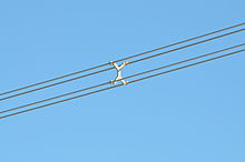
A bundle conductor

For transmission of power across long distances, high voltage transmission is employed. Transmission higher than 132 kV poses the problem of corona discharge, which causes significant power loss and interference with communication circuits. To reduce this corona effect, it is preferable to use more than one conductor per phase, or bundled conductors. In addition to reducing corona, audible and radio noise (and associated electrical losses), bundled conductors also increase the amount of current that can be carried compared to a single conductor of equal aluminum content due to the skin effect (for AC lines).

Bundle conductors consist of several parallel cables connected at intervals by spacers, often in a cylindrical configuration. The optimum number of conductors depends on the current rating, but typically higher-voltage lines also have higher current. American Electric Power is building 765 kV lines using six conductors per phase in a bundle. Spacers must resist the forces due to wind, and magnetic forces during a short circuit.

Spacer damper for four-conductor bundles
Bundle conductor attachment

Bundled conductors reduce the electric field gradient in the vicinity of the line, to reduce the possibility of corona discharge. At extra high voltage, the electric field gradient at the surface of a single conductor is high enough to ionize air, which wastes power, generates unwanted audible noise and interferes with communication systems. The field surrounding a bundle of conductors is similar to the field that would surround a single, very large conductor—this produces lower gradients which mitigates issues associated with high field strength. The transmission efficiency is improved as loss due to corona effect is countered.

Bundled conductors cool themselves more efficiently due to the increased surface area of the conductors, further reducing line losses. When transmitting alternating current, bundle conductors also avoid the reduction in ampacity of a single large conductor due to the skin effect. A bundle conductor also has lower reactance, compared to a single conductor.

While wind resistance is higher, wind-induced oscillation can be damped at bundle spacers. The ice and wind loading of bundled conductors will be greater than a single conductor of the same total cross section, and bundled conductors are more difficult to install than single conductors. Aeolian vibration is generally less pronounced on bundled conductors due to the effect of spacers and spacer dampers installed at relatively close intervals along the line.

Ground wires

Aluminum conductor crosslinked polyethylene insulation wire. It is used for 6600V power lines.

Overhead power lines are often equipped with a ground conductor (shield wire, static wire, or overhead earth wire). The ground conductor is usually grounded (earthed) at the top of the supporting structure, to minimize the likelihood of direct lightning strikes to the phase conductors. It also serves as a parallel path with the earth for fault currents. Very high-voltage transmission lines may have two ground conductors. These are either at the outermost ends of the highest cross beam, at two V-shaped mast points, or at a separate cross arm. Older lines may use surge arresters every few spans in place of a shield wire; this configuration is typically found in the more rural areas of the United States. By protecting the line from lightning, the design of apparatus in substations is simplified due to lower stress on insulation. Shield wires on transmission lines may include optical fibers (optical ground wires/OPGW), used for communication and control of the power system.

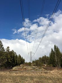
HVDC Fenno-Skan with ground wires used as electrode line

At some HVDC converter stations, the ground wire is used also as the electrode line to connect to a distant grounding electrode. This allows the HVDC system to use the earth as one conductor. The ground conductor is mounted on small insulators bridged by lightning arrestors above the phase conductors. The insulation prevents electrochemical corrosion of the pylon.

Medium-voltage distribution lines may also use one or two shield wires, or may have the grounded conductor strung below the phase conductors to provide some measure of protection against tall vehicles or equipment touching the energized line, as well as to provide a neutral line in Wye wired systems.

On some power lines for very high voltages in the former Soviet Union, the ground wire is used for PLC-radio systems and mounted on insulators at the pylons.

Insulated conductors and cable

Overhead insulated cables are rarely used, usually for short distances (less than a kilometer). Insulated cables can be directly fastened to structures without insulating supports. An overhead line with bare conductors insulated by air is typically less costly than a cable with insulated conductors.

A more common approach is "covered" line wire. It is treated as bare cable, but often is safer for wildlife, as the insulation on the cables increases the likelihood of a large-wing-span raptor to survive a brush with the lines, and reduces the overall danger of the lines slightly. These types of lines are often seen in the eastern United States and in heavily wooded areas, where tree-line contact is likely. The only pitfall is cost, as insulated wire is often costlier than its bare counterpart. Many utility companies implement covered line wire as jumper material where the wires are often closer to each other on the pole, such as an underground riser/pothead, and on reclosers, cutouts and the like.

Dampers

A Stockbridge damper

Because power lines can suffer from aeroelastic flutter and "galloping" oscillations driven by wind, tuned mass dampers are often attached to the line, to change the characteristics of the line's physical oscillations. A common type is the Stockbridge damper.

Compact transmission lines

Medium-voltage compact overhead power line mounted on a concrete pole in Thailand. The appearance is similar to a bundle conductor, but this line consists of three conductors, which are attached to a single, cross-shaped porcellain insulator.

A compact overhead transmission line requires a smaller right of way than a standard overhead powerline. Conductors must not get too close to each other. This can be achieved either by short span lengths and insulating crossbars, or by separating the conductors in the span with insulators. The first type is easier to build as it does not require insulators in the span, which may be difficult to install and to maintain.

Examples of compact lines are:

Compact transmission lines may be designed for voltage upgrade of existing lines to increase the power that can be transmitted on an existing right of way.

Low voltage

Aerial bundled cable in Old Coulsdon, Surrey

Low voltage overhead lines may use either bare conductors carried on glass or ceramic insulators or an aerial bundled cable system. The number of conductors may be anywhere between two (most likely a phase and neutral) up to as many as six (three phase conductors, separate neutral and earth plus street lighting supplied by a common switch); a common case is four (three phase and neutral, where the neutral might also serve as a protective earthing conductor).

Train power

Overhead lines or overhead wires are used to transmit electrical energy to trams, trolleybuses and trains. Overhead lines are designed on the principle of one or more overhead wires situated over rail tracks. Feeder stations at regular intervals along the overhead line supply power from the high-voltage grid. In some cases, low-frequency AC is used, and distributed by a special traction current network.

Further applications

Overhead lines are also occasionally used to supply transmitting antennas, especially for efficient transmission of long, medium and short waves. For this purpose a staggered array line is often used. Along a staggered array line the conductor cables for the supply of the earth net of the transmitting antenna are attached on the exterior of a ring, while the conductor inside the ring, is fastened to insulators leading to the high-voltage standing feeder of the antenna.

Use of area under overhead power lines

Use of the area below an overhead line is limited because objects must not come too close to the energized conductors. Overhead lines and structures may shed ice, creating a hazard. Radio reception can be impaired under a power line, due both to shielding of a receiver antenna by the overhead conductors, and by partial discharge at insulators and sharp points of the conductors which creates radio noise.

In the area surrounding the overhead lines, it is dangerous to risk interference, e.g. flying kites or balloons, using ladders, or operating machinery.

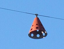
Overhead distribution and transmission lines near airfields are often marked on maps, and the lines themselves marked with conspicuous plastic reflectors, to warn pilots of the presence of conductors.

Construction of overhead power lines, especially in wilderness areas, may have significant environmental effects. Environmental studies for such projects may consider the effect of bush clearing, changed migration routes for migratory animals, possible access by predators and humans along transmission corridors, disturbances of fish habitat at stream crossings, and other effects.

Linear parks will usually occupy the area under overhead power lines, to provide easy access, and prevent obstacles.

Aviation accidents

An aviation obstruction marker on a high-voltage overhead transmission line reminds pilots of the presence of an overhead line. Some markers are lit at night or have strobe lights.
The Ekibastuz–Kokshetau high-voltage line in Kazakhstan. It was the first commercially used power line which operated at 1150 kV, the highest transmission line voltage in the world.

General aviation, hang gliding, paragliding, skydiving, balloon, and kite flying must avoid accidental contact with power lines. Nearly every kite product warns users to stay away from power lines. Deaths occur when aircraft crash into power lines. Some power lines are marked with obstruction makers, especially near air strips or over waterways that may support floatplane operations. The placement of power lines sometimes use up sites that would otherwise be used by hang gliders.

History

The first transmission of electrical impulses over an extended distance was demonstrated on July 14, 1729, by the physicist Stephen Gray. The demonstration used damp hemp cords suspended by silk threads (the low resistance of metallic conductors not being appreciated at the time).

However the first practical use of overhead lines was in the context of telegraphy. By 1837 experimental commercial telegraph systems ran as far as 20 km (13 miles). Electric power transmission was accomplished in 1882 with the first high-voltage transmission between Munich and Miesbach (60 km). 1891 saw the construction of the first three-phase alternating current overhead line on the occasion of the International Electricity Exhibition in Frankfurt, between Lauffen and Frankfurt.

In 1912 the first 110 kV-overhead power line entered service followed by the first 220 kV-overhead power line in 1923. In the 1920s RWE AG built the first overhead line for this voltage and in 1926 built a Rhine crossing with the pylons of Voerde, two masts 138 meters high.

In 1953, the first 345 kV line was built by The L.E. Myers Co. and put into service by the Ohio Valley Electric Corporation in the United States. In Germany in 1957 the first 380 kV overhead power line was commissioned (between the transformer station and Rommerskirchen). In the same year the overhead line traversing of the Strait of Messina went into service in Italy, whose pylons served the Elbe crossing 1. This was used as the model for the building of the Elbe crossing 2 in the second half of the 1970s which saw the construction of the highest overhead line pylons of the world. Earlier, in 1952, the first 380 kV line was put into service in Sweden, in 1000 km (625 miles) between the more populated areas in the south and the largest hydroelectric power stations in the north. Starting from 1967 in Russia, and also in the US and Canada, overhead lines for voltage of 765 kV were built. In 1982 overhead power lines were built in Soviet Union between Elektrostal and the power station at Ekibastuz, this was a three-phase alternating current line at 1150 kV (Powerline Ekibastuz-Kokshetau). In 1999, in Japan the first powerline designed for 1000 kV with 2 circuits were built, the Kita-Iwaki Powerline. In 2003 the building of the highest overhead line commenced in China, the Yangtze River Crossing.

Mathematical analysis

An overhead power line is one example of a transmission line. At power system frequencies, many useful simplifications can be made for lines of typical lengths. For analysis of power systems, the distributed resistance, series inductance, shunt leakage resistance and shunt capacitance can be replaced with suitable lumped values or simplified networks.

Short and medium line model

A short length of a power line (less than 80 km) can be approximated with a resistance in series with an inductance and ignoring the shunt admittances. This value is not the total impedance of the line, but rather the series impedance per unit length of line. For a longer length of line (800–2500 m), a shunt capacitance is added to the model. In this case it is common to distribute half of the total capacitance to each side of the line. As a result, the power line can be represented as a two-port network, such as with ABCD parameters. waitwhat.jpg. The circuit can be characterized as

where

The medium line has an additional shunt admittance

where

  • Y is the total shunt line admittance
  • y is the shunt admittance per unit length


Tumor necrosis factor

From Wikipedia, the free encyclopedia
https://en.wikipedia.org/wiki/Tumor_necrosis_factor

TNF

Tumor necrosis factor (TNF, cachexin, or cachectin; formerly known as tumor necrosis factor alpha or TNF-α) is an adipokine and a cytokine. TNF is a member of the TNF superfamily, which consists of various transmembrane proteins with a homologous TNF domain.

As an adipokine, TNF promotes insulin resistance, and is associated with obesity-induced type 2 diabetes. As a cytokine, TNF is used by the immune system for cell signaling. If macrophages (certain white blood cells) detect an infection, they release TNF to alert other immune system cells as part of an inflammatory response.

TNF signaling occurs through two receptors: TNFR1 and TNFR2. TNFR1 is constituitively expressed on most cell types, whereas TNFR2 is restricted primarily to endothelial, epithelial, and subsets of immune cells. TNFR1 signaling tends to be pro-inflammatory and apoptotic, whereas TNFR2 signaling is anti-inflammatory and promotes cell proliferation. Suppression of TNFR1 signaling has been important for treatment of autoimmune disease, whereas TNFR2 signaling promotes wound healing.

TNF-α exists as a transmembrane form (mTNF-α) and as a soluble form (sTNF-α). sTNF-α results from enzymatic cleavage of mTNF-α, by a process called substrate presentation. mTNF-α is mainly found on monocytes/macrophages where it interacts with tissue receptors by cell-to-cell contact. sTNF-α selectively binds to TNFR1, whereas mTNF-α binds to both TNFR1 and TNFR2. TNF-α binding to TNFR1 is irreversible, whereas binding to TNFR2 is reversible.

The primary role of TNF is in the regulation of immune cells. TNF, as an endogenous pyrogen, is able to induce fever, apoptotic cell death, cachexia, and inflammation, inhibit tumorigenesis and viral replication, and respond to sepsis via IL-1 and IL-6-producing cells. Dysregulation of TNF production has been implicated in a variety of human diseases including Alzheimer's disease, cancer, major depression, psoriasis and inflammatory bowel disease (IBD). Though controversial, some studies have linked depression and IBD to increased levels of TNF.

Under the name tasonermin, TNF is used as an immunostimulant drug in the treatment of certain cancers. Drugs that counter the action of TNF are used in the treatment of various inflammatory diseases, for instance rheumatoid arthritis.

Certain cancers can cause overproduction of TNF. TNF parallels parathyroid hormone both in causing secondary hypercalcemia and in the cancers with which excessive production is associated.

Discovery

The theory of an anti-tumoral response of the immune system in vivo was recognized by the physician William B. Coley. In 1968, Gale A Granger from the University of California, Irvine, reported a cytotoxic factor produced by lymphocytes and named it lymphotoxin (LT). Credit for this discovery is shared by Nancy H. Ruddle from Yale University, who reported the same activity in a series of back-to-back articles published in the same month. Subsequently, in 1975 Lloyd J. Old from Memorial Sloan-Kettering Cancer Center, New York, reported another cytotoxic factor produced by macrophages and named it tumor necrosis factor (TNF). Both factors were described based on their ability to kill mouse fibrosarcoma L-929 cells. These concepts were extended to systemic disease in 1981, when Ian A. Clark, from the Australian National University, in collaboration with Elizabeth Carswell in Old's group, working with pre-sequencing era data, reasoned that excessive production of TNF causes malaria disease and endotoxin poisoning.

The cDNAs encoding LT and TNF were cloned in 1984 and were revealed to be similar. The binding of TNF to its receptor and its displacement by LT confirmed the functional homology between the two factors. The sequential and functional homology of TNF and LT led to the renaming of TNF as TNFα and LT as TNFβ. In 1985, Bruce A. Beutler and Anthony Cerami discovered that cachectin (a hormone which induces cachexia) was actually TNF. They then identified TNF as a mediator of lethal endotoxin poisoning. Kevin J. Tracey and Cerami discovered the key mediator role of TNF in lethal septic shock, and identified the therapeutic effects of monoclonal anti-TNF antibodies.

Research in the Laboratory of Mark Mattson has shown that TNF can prevent the death/apoptosis of neurons by a mechanism involving activation of the transcription factor NF-κB which induces the expression of antioxidant enzymes and Bcl-2.

Gene

The human TNF gene was cloned in 1985. It maps to chromosome 6p21.3, spans about 3 kilobases and contains 4 exons. The last exon shares similarity with lymphotoxin alpha (LTA, once named as TNF-β). The three prime untranslated region (3'-UTR) of TNF contains an AU-rich element (ARE).

Structure

TNF is primarily produced as a 233-amino acid-long type II transmembrane protein arranged in stable homotrimers. From this membrane-integrated form the soluble homotrimeric cytokine (sTNF) is released via proteolytic cleavage by the metalloprotease TNF alpha converting enzyme (TACE, also called ADAM17). The soluble 51 kDa trimeric sTNF tends to dissociate at concentrations below the nanomolar range, thereby losing its bioactivity. The secreted form of human TNF takes on a triangular pyramid shape, and weighs around 17-kDa. Both the secreted and the membrane bound forms are biologically active, although the specific functions of each is controversial. But, both forms do have overlapping and distinct biological activities.

The common house mouse TNF and human TNF are structurally different. The 17-kilodalton (kDa) TNF protomers (185-amino acid-long) are composed of two antiparallel β-pleated sheets with antiparallel β-strands, forming a 'jelly roll' β-structure, typical for the TNF family, but also found in viral capsid proteins.

Cell signaling

TNF can bind two receptors, TNFR1 (TNF receptor type 1; CD120a; p55/60) and TNFR2 (TNF receptor type 2; CD120b; p75/80). TNFR1 is 55-kDa and TNFR2 is 75-kDa. TNFR1 is expressed in most tissues, and can be fully activated by both the membrane-bound and soluble trimeric forms of TNF, whereas TNFR2 is found typically in cells of the immune system, and responds to the membrane-bound form of the TNF homotrimer. As most information regarding TNF signaling is derived from TNFR1, the role of TNFR2 is likely underestimated. At least partly because TNFR2 has no intracellular death domain, it shows neuroprotective properties.

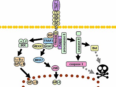
Signaling pathway of TNFR1. Dashed grey lines represent multiple steps.

Upon contact with their ligand, TNF receptors also form trimers, their tips fitting into the grooves formed between TNF monomers. This binding causes a conformational change to occur in the receptor, leading to the dissociation of the inhibitory protein SODD from the intracellular death domain. This dissociation enables the adaptor protein TRADD to bind to the death domain, serving as a platform for subsequent protein binding. Following TRADD binding, three pathways can be initiated.

  • Activation of NF-κB: TRADD recruits TRAF2 and RIP. TRAF2 in turn recruits the multicomponent protein kinase IKK, enabling the serine-threonine kinase RIP to activate it. An inhibitory protein, IκBα, that normally binds to NF-κB and inhibits its translocation, is phosphorylated by IKK and subsequently degraded, releasing NF-κB. NF-κB is a heterodimeric transcription factor that translocates to the nucleus and mediates the transcription of a vast array of proteins involved in cell survival and proliferation, inflammatory response, and anti-apoptotic factors.
  • Activation of the MAPK pathways: Of the three major MAPK cascades, TNF induces a strong activation of the stress-related JNK group, evokes moderate response of the p38-MAPK, and is responsible for minimal activation of the classical ERKs. TRAF2/Rac activates the JNK-inducing upstream kinases of MLK2/MLK3, TAK1, MEKK1 and ASK1 (either directly or through GCKs and Trx, respectively). SRC- Vav- Rac axis activates MLK2/MLK3 and these kinases phosphorylate MKK7, which then activates JNK. JNK translocates to the nucleus and activates transcription factors such as c-Jun and ATF2. The JNK pathway is involved in cell differentiation, proliferation, and is generally pro-apoptotic.
  • Induction of death signaling: Like all death-domain-containing members of the TNFR superfamily, TNFR1 is involved in death signaling. However, TNF-induced cell death plays only a minor role compared to its overwhelming functions in the inflammatory process. Its death-inducing capability is weak compared to other family members (such as Fas), and often masked by the anti-apoptotic effects of NF-κB. Nevertheless, TRADD binds FADD, which then recruits the cysteine protease caspase-8. A high concentration of caspase-8 induces its autoproteolytic activation and subsequent cleaving of effector caspases, leading to cell apoptosis.

The myriad and often-conflicting effects mediated by the above pathways indicate the existence of extensive cross-talk. For instance, NF-κB enhances the transcription of C-FLIP, Bcl-2, and cIAP1 / cIAP2, inhibitory proteins that interfere with death signaling. On the other hand, activated caspases cleave several components of the NF-κB pathway, including RIP, IKK, and the subunits of NF-κB itself. Other factors, such as cell type, concurrent stimulation of other cytokines, or the amount of reactive oxygen species (ROS) can shift the balance in favor of one pathway or another. Such complicated signaling ensures that, whenever TNF is released, various cells with vastly diverse functions and conditions can all respond appropriately to inflammation. Both protein molecules tumor necrosis factor alpha and keratin 17 appear to be related in case of oral submucous fibrosis

In animal models TNF selectively kills autoreactive T cells.

There is also evidence that TNF-α signaling triggers downstream epigenetic modifications that result in lasting enhancement of pro-inflammatory responses in cells.

Enzyme regulation

This protein may use the morpheein model of allosteric regulation.

Clinical significance

TNF was thought to be produced primarily by macrophages, but it is produced also by a broad variety of cell types including lymphoid cells, mast cells, endothelial cells, cardiac myocytes, adipose tissue, fibroblasts, and neurons. Large amounts of TNF are released in response to lipopolysaccharide, other bacterial products, and interleukin-1 (IL-1). In the skin, mast cells appear to be the predominant source of pre-formed TNF, which can be released upon inflammatory stimulus (e.g., LPS).

It has a number of actions on various organ systems, generally together with IL-1 and interleukin-6 (IL-6):

A local increase in concentration of TNF will cause the cardinal signs of Inflammation to occur: heat, swelling, redness, pain and loss of function.

Whereas high concentrations of TNF induce shock-like symptoms, the prolonged exposure to low concentrations of TNF can result in cachexia, a wasting syndrome. This can be found, for example, in cancer patients.

Said et al. showed that TNF causes an IL-10-dependent inhibition of CD4 T-cell expansion and function by up-regulating PD-1 levels on monocytes which leads to IL-10 production by monocytes after binding of PD-1 by PD-L.

The research of Pedersen et al. indicates that TNF increase in response to sepsis is inhibited by the exercise-induced production of myokines. To study whether acute exercise induces a true anti-inflammatory response, a model of 'low grade inflammation' was established in which a low dose of E. coli endotoxin was administered to healthy volunteers, who had been randomised to either rest or exercise prior to endotoxin administration. In resting subjects, endotoxin induced a 2- to 3-fold increase in circulating levels of TNF. In contrast, when the subjects performed 3 hours of ergometer cycling and received the endotoxin bolus at 2.5 h, the TNF response was totally blunted. This study provides some evidence that acute exercise may inhibit TNF production.

In the brain TNF can protect against excitotoxicity. TNF strengthens synapses. TNF in neurons promotes their survival, whereas TNF in macrophages and microglia results in neurotoxins that induce apoptosis.

TNF-α and IL-6 concentrations are elevated in obesity. Monoclonal antibody against TNF-α is associated with increases rather than decreases in obesity, indicating that inflammation is the result, rather than the cause, of obesity. TNF and IL-6 are the most prominent cytokines predicting COVID-19 severity and death.

Pharmacology

TNF promotes the inflammatory response, which, in turn, causes many of the clinical problems associated with autoimmune disorders such as rheumatoid arthritis, ankylosing spondylitis, inflammatory bowel disease, psoriasis, hidradenitis suppurativa and refractory asthma. These disorders are sometimes treated by using a TNF inhibitor. This inhibition can be achieved with a monoclonal antibody such as infliximab (Remicade) binding directly to TNF, adalimumab (Humira), certolizumab pegol (Cimzia) or with a decoy circulating receptor fusion protein such as etanercept (Enbrel) which binds to TNF with greater affinity than the TNFR.

On the other hand, some patients treated with TNF inhibitors develop an aggravation of their disease or new onset of autoimmunity. TNF seems to have an immunosuppressive facet as well. One explanation for a possible mechanism is this observation that TNF has a positive effect on regulatory T cells (Tregs), due to its binding to the tumor necrosis factor receptor 2 (TNFR2).

Anti-TNF therapy has shown only modest effects in cancer therapy. Treatment of renal cell carcinoma with infliximab resulted in prolonged disease stabilization in certain patients. Etanercept was tested for treating patients with breast cancer and ovarian cancer showing prolonged disease stabilization in certain patients via downregulation of IL-6 and CCL2. On the other hand, adding infliximab or etanercept to gemcitabine for treating patients with advanced pancreatic cancer was not associated with differences in efficacy when compared with placebo.

Interactions

TNF has been shown to interact with TNFRSF1A.

Nomenclature

Because LTα is no longer referred to as TNFβ, TNFα, as the previous gene symbol, is now simply called TNF, as shown in HGNC (HUGO Gene Nomenclature Committee) database.

Distance education

From Wikipedia, the free encyclopedia https://en.wikipedia.org/wiki/Distance_...