Search This Blog

Friday, October 20, 2023

Lens

From Wikipedia, the free encyclopedia
https://en.wikipedia.org/wiki/Lens
A burning apparatus consisting of two biconvex lens

A lens is a transmissive optical device that focuses or disperses a light beam by means of refraction. A simple lens consists of a single piece of transparent material, while a compound lens consists of several simple lenses (elements), usually arranged along a common axis. Lenses are made from materials such as glass or plastic and are ground, polished, or molded to the required shape. A lens can focus light to form an image, unlike a prism, which refracts light without focusing. Devices that similarly focus or disperse waves and radiation other than visible light are also called "lenses", such as microwave lenses, electron lenses, acoustic lenses, or explosive lenses.

Lenses are used in various imaging devices such as telescopes, binoculars, and cameras. They are also used as visual aids in glasses to correct defects of vision such as myopia and hypermetropia.

History

Light being refracted by a spherical glass container full of water. Roger Bacon, 13th century
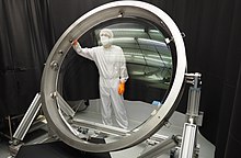
Lens for LSST, a planned sky surveying telescope

The word lens comes from lēns, the Latin name of the lentil (a seed of a lentil plant), because a double-convex lens is lentil-shaped. The lentil also gives its name to a geometric figure.[a]

Some scholars argue that the archeological evidence indicates that there was widespread use of lenses in antiquity, spanning several millennia. The so-called Nimrud lens is a rock crystal artifact dated to the 7th century BCE which may or may not have been used as a magnifying glass, or a burning glass. Others have suggested that certain Egyptian hieroglyphs depict "simple glass meniscal lenses".

The oldest certain reference to the use of lenses is from Aristophanes' play The Clouds (424 BCE) mentioning a burning-glass. Pliny the Elder (1st century) confirms that burning-glasses were known in the Roman period. Pliny also has the earliest known reference to the use of a corrective lens when he mentions that Nero was said to watch the gladiatorial games using an emerald (presumably concave to correct for nearsightedness, though the reference is vague). Both Pliny and Seneca the Younger (3 BC–65 AD) described the magnifying effect of a glass globe filled with water.

Ptolemy (2nd century) wrote a book on Optics, which however survives only in the Latin translation of an incomplete and very poor Arabic translation. The book was, however, received by medieval scholars in the Islamic world, and commented upon by Ibn Sahl (10th century), who was in turn improved upon by Alhazen (Book of Optics, 11th century). The Arabic translation of Ptolemy's Optics became available in Latin translation in the 12th century (Eugenius of Palermo 1154). Between the 11th and 13th century "reading stones" were invented. These were primitive plano-convex lenses initially made by cutting a glass sphere in half. The medieval (11th or 12th century) rock crystal Visby lenses may or may not have been intended for use as burning glasses.

Spectacles were invented as an improvement of the "reading stones" of the high medieval period in Northern Italy in the second half of the 13th century. This was the start of the optical industry of grinding and polishing lenses for spectacles, first in Venice and Florence in the late 13th century, and later in the spectacle-making centres in both the Netherlands and Germany. Spectacle makers created improved types of lenses for the correction of vision based more on empirical knowledge gained from observing the effects of the lenses (probably without the knowledge of the rudimentary optical theory of the day). The practical development and experimentation with lenses led to the invention of the compound optical microscope around 1595, and the refracting telescope in 1608, both of which appeared in the spectacle-making centres in the Netherlands.

With the invention of the telescope and microscope there was a great deal of experimentation with lens shapes in the 17th and early 18th centuries by those trying to correct chromatic errors seen in lenses. Opticians tried to construct lenses of varying forms of curvature, wrongly assuming errors arose from defects in the spherical figure of their surfaces. Optical theory on refraction and experimentation was showing no single-element lens could bring all colours to a focus. This led to the invention of the compound achromatic lens by Chester Moore Hall in England in 1733, an invention also claimed by fellow Englishman John Dollond in a 1758 patent.

Construction of simple lenses

Most lenses are spherical lenses: their two surfaces are parts of the surfaces of spheres. Each surface can be convex (bulging outwards from the lens), concave (depressed into the lens), or planar (flat). The line joining the centres of the spheres making up the lens surfaces is called the axis of the lens. Typically the lens axis passes through the physical centre of the lens, because of the way they are manufactured. Lenses may be cut or ground after manufacturing to give them a different shape or size. The lens axis may then not pass through the physical centre of the lens.

Toric or sphero-cylindrical lenses have surfaces with two different radii of curvature in two orthogonal planes. They have a different focal power in different meridians. This forms an astigmatic lens. An example is eyeglass lenses that are used to correct astigmatism in someone's eye.

Types of simple lenses
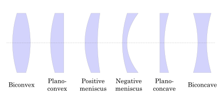
Types of lenses
Types of lenses

Lenses are classified by the curvature of the two optical surfaces. A lens is biconvex (or double convex, or just convex) if both surfaces are convex. If both surfaces have the same radius of curvature, the lens is equiconvex. A lens with two concave surfaces is biconcave (or just concave). If one of the surfaces is flat, the lens is plano-convex or plano-concave depending on the curvature of the other surface. A lens with one convex and one concave side is convex-concave or meniscus. It is this type of lens that is most commonly used in corrective lenses, since its shape minimizes some aberrations.

If the lens is biconvex or plano-convex, a collimated beam of light passing through the lens converges to a spot (a focus) behind the lens. In this case, the lens is called a positive or converging lens. For a thin lens in air, the distance from the lens to the spot is the focal length of the lens, which is commonly represented by f in diagrams and equations. An extended hemispherical lens is a special type of plano-convex lens, in which the lens's curved surface is a full hemisphere and the lens is much thicker than the radius of curvature.

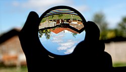
Another extreme case of a thick convex lens is a ball lens, whose shape is completely round. When used in novelty photography it is often called a "lensball". A ball-shaped lens has the advantage of being omnidirectional, but for most optical glass types, its focal point lies close to the ball's surface . Because of the ball's curvature extremes compared to the lens size, optical aberration is much worse than thin lenses, with the notable exception of chromatic aberration.
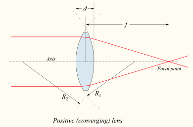
Biconvex lens

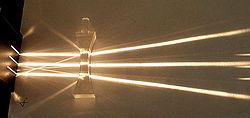
If the lens is biconcave or plano-concave, a collimated beam of light passing through the lens is diverged (spread); the lens is thus called a negative or diverging lens. The beam, after passing through the lens, appears to emanate from a particular point on the axis in front of the lens. For a thin lens in air, the distance from this point to the lens is the focal length, though it is negative with respect to the focal length of a converging lens.

Biconcave lens
Meniscus lenses: negative (top) and positive (bottom)

Convex-concave (meniscus) lenses can be either positive or negative, depending on the relative curvatures of the two surfaces. A negative meniscus lens has a steeper concave surface (with a shorter radius than the convex surface) and is thinner at the centre than at the periphery. Conversely, a positive meniscus lens has a steeper convex surface (with a shorter radius than the concave surface) and is thicker at the centre than at the periphery.

An ideal thin lens with two surfaces of equal curvature would have zero optical power, meaning that it would neither converge nor diverge light. All real lenses have a nonzero thickness, however, which makes a real lens with identical curved surfaces slightly positive. To obtain exactly zero optical power, a meniscus lens must have slightly unequal curvatures to account for the effect of the lens' thickness.

For a spherical surface

Simulation of refraction at spherical surface at Desmos

For a single refraction for a circular boundary, the relation between object and image is given by

where R is the radius of the spherical surface, n2 is the refractive index of the surface, and n1 is the refractive index of medium.

Applying this on the two spherical surfaces of a thin lens leads to the lens maker's formula.

Derivation

The four cases of spherical refraction

Applying Snell's law on the spherical surface,

Also in the diagram,

Using small angle approximation and eliminating i, r, and θ,

Lensmaker's equation

Simulation of the effect of lenses with different curvatures of the two facets on a collimated Gaussian beam.
The position of the focus of a spherical lens depends on the radii of curvature of the two facets.

The focal length of a lens in air can be calculated from the lensmaker's equation:

where

  • f  is the focal length of the lens;
  • n is the refractive index of the lens material;
  • R1 is the (signed, see below) radius of curvature of the lens surface closer to the light source;
  • R2 is the radius of curvature of the lens surface farther from the light source; and
  • d is the thickness of the lens (the distance along the lens axis between the two surface vertices).

The focal length f is positive for converging lenses, and negative for diverging lenses. The reciprocal of the focal length, f−1, is the optical power of the lens. If the focal length is in metres, this gives the optical power in dioptres (inverse metres).

Lenses have the same focal length when light travels from the back to the front as when light goes from the front to the back. Other properties of the lens, such as the aberrations are not the same in both directions.

Sign convention for radii of curvature R1 and R2

The signs of the lens' radii of curvature indicate whether the corresponding surfaces are convex or concave. The sign convention used to represent this varies, but in this article a positive R indicates a surface's center of curvature is further along in the direction of the ray travel (right, in the accompanying diagrams), while negative R means that rays reaching the surface have already passed the center of curvature. Consequently, for external lens surfaces as diagrammed above, R1 > 0 and R2 < 0 indicate convex surfaces (used to converge light in a positive lens), while R1 < 0 and Rs > 0 indicate concave surfaces. The reciprocal of the radius of curvature is called the curvature. A flat surface has zero curvature, and its radius of curvature is infinite.

Thin lens approximation

If d is small compared to R1 and R2 then the thin lens approximation can be made. For a lens in air, f  is then given by

Imaging properties

As mentioned above, a positive or converging lens in air focuses a collimated beam travelling along the lens axis to a spot (known as the focal point) at a distance f from the lens. Conversely, a point source of light placed at the focal point is converted into a collimated beam by the lens. These two cases are examples of image formation in lenses. In the former case, an object at an infinite distance (as represented by a collimated beam of waves) is focused to an image at the focal point of the lens. In the latter, an object at the focal length distance from the lens is imaged at infinity. The plane perpendicular to the lens axis situated at a distance f from the lens is called the focal plane.

If the distances from the object to the lens and from the lens to the image are S1 and S respectively, for a lens of negligible thickness (thin lens), in air, the distances are related by the thin lens formula:

This can also be put into the "Newtonian" form:

where and

A camera lens forms a real image of a distant object.

Therefore, if an object is placed at a distance S1 > f from a positive lens of focal length f, we will find an image distance S2 according to this formula. If a screen is placed at a distance S2 on the opposite side of the lens, an image is formed on it. This sort of image, which can be projected onto a screen or image sensor, is known as a real image. This is the principle of the camera, and also of the human eye, in which the retina serves as the image sensor.

The focusing adjustment of a camera adjusts S2, as using an image distance different from that required by this formula produces a defocused (fuzzy) image for an object at a distance of S1 from the camera. Put another way, modifying S2 causes objects at a different S1 to come into perfect focus.

Virtual image formation using a positive lens as a magnifying glass.

In some cases S2 is negative, indicating that the image is formed on the opposite side of the lens from where those rays are being considered. Since the diverging light rays emanating from the lens never come into focus, and those rays are not physically present at the point where they appear to form an image, this is called a virtual image. Unlike real images, a virtual image cannot be projected on a screen, but appears to an observer looking through the lens as if it were a real object at the location of that virtual image. Likewise, it appears to a subsequent lens as if it were an object at that location, so that second lens could again focus that light into a real image, S1 then being measured from the virtual image location behind the first lens to the second lens. This is exactly what the eye does when looking through a magnifying glass. The magnifying glass creates a (magnified) virtual image behind the magnifying glass, but those rays are then re-imaged by the lens of the eye to create a real image on the retina.

A negative lens produces a demagnified virtual image.
 
A Barlow lens (B) reimages a virtual object (focus of red ray path) into a magnified real image (green rays at focus)

Using a positive lens of focal length f, a virtual image results when S1 < f, the lens thus being used as a magnifying glass (rather than if S1f as for a camera). Using a negative lens (f < 0) with a real object (S1 > 0) can only produce a virtual image (S2 < 0), according to the above formula. It is also possible for the object distance S1 to be negative, in which case the lens sees a so-called virtual object. This happens when the lens is inserted into a converging beam (being focused by a previous lens) before the location of its real image. In that case even a negative lens can project a real image, as is done by a Barlow lens.

Real image of a lamp is projected onto a screen (inverted). Reflections of the lamp from both surfaces of the biconvex lens are visible.
 
A convex lens (fS1) forming a real, inverted image (as the image formed by the objective lens of a telescope or binoculars) rather than the upright, virtual image as seen in a magnifying glass(f > S1). This real image may also be viewed when put on a screen.

For a thin lens, the distances S1 and S2 are measured from the object and image to the position of the lens, as described above. When the thickness of the lens is not much smaller than S1 and S2 or there are multiple lens elements (a compound lens), one must instead measure from the object and image to the principal planes of the lens. If distances S1 or S2 pass through a medium other than air or vacuum a more complicated analysis is required.

Magnification

The linear magnification of an imaging system using a single lens is given by

where M is the magnification factor defined as the ratio of the size of an image compared to the size of the object. The sign convention here dictates that if M is negative, as it is for real images, the image is upside-down with respect to the object. For virtual images M is positive, so the image is upright.

This magnification formula provides two easy ways to distinguish converging (f > 0) and diverging (f < 0) lenses: For an object very close to the lens (0 < S1 < |f|), a converging lens would form a magnified (bigger) virtual image, whereas a diverging lens would form a demagnified (smaller) image; For an object very far from the lens (S1 > |f| > 0), a converging lens would form an inverted image, whereas a diverging lens would form an upright image.

Linear magnification M is not always the most useful measure of magnifying power. For instance, when characterizing a visual telescope or binoculars that produce only a virtual image, one would be more concerned with the angular magnification—which expresses how much larger a distant object appears through the telescope compared to the naked eye. In the case of a camera one would quote the plate scale, which compares the apparent (angular) size of a distant object to the size of the real image produced at the focus. The plate scale is the reciprocal of the focal length of the camera lens; lenses are categorized as long-focus lenses or wide-angle lenses according to their focal lengths.

Using an inappropriate measurement of magnification can be formally correct but yield a meaningless number. For instance, using a magnifying glass of 5 cm focal length, held 20 cm from the eye and 5 cm from the object, produces a virtual image at infinity of infinite linear size: M = ∞. But the angular magnification is 5, meaning that the object appears 5 times larger to the eye than without the lens. When taking a picture of the moon using a camera with a 50 mm lens, one is not concerned with the linear magnification M−50 mm / 380000 km = −1.3×10⁻¹⁰. Rather, the plate scale of the camera is about 1°/mm, from which one can conclude that the 0.5 mm image on the film corresponds to an angular size of the moon seen from earth of about 0.5°.

In the extreme case where an object is an infinite distance away, S1 = ∞, S2 = f and M = −f/∞ = 0, indicating that the object would be imaged to a single point in the focal plane. In fact, the diameter of the projected spot is not actually zero, since diffraction places a lower limit on the size of the point spread function. This is called the diffraction limit.

Images of black letters in a thin convex lens of focal length f are shown in red. Selected rays are shown for letters E, I and K in blue, green and orange, respectively. E (at 2f) has an equal-size, real and inverted image; I (at f) has its image at infinity; and K (at f/2) has a double-size, virtual and upright image.

Aberrations

Lenses do not form perfect images, and a lens always introduces some degree of distortion or aberration that makes the image an imperfect replica of the object. Careful design of the lens system for a particular application minimizes the aberration. Several types of aberration affect image quality, including spherical aberration, coma, and chromatic aberration.

Spherical aberration

Spherical aberration occurs because spherical surfaces are not the ideal shape for a lens, but are by far the simplest shape to which glass can be ground and polished, and so are often used. Spherical aberration causes beams parallel to, but distant from, the lens axis to be focused in a slightly different place than beams close to the axis. This manifests itself as a blurring of the image. Spherical aberration can be minimised with normal lens shapes by carefully choosing the surface curvatures for a particular application. For instance, a plano-convex lens, which is used to focus a collimated beam, produces a sharper focal spot when used with the convex side towards the beam source.

Coma

Coma, or comatic aberration, derives its name from the comet-like appearance of the aberrated image. Coma occurs when an object off the optical axis of the lens is imaged, where rays pass through the lens at an angle to the axis θ. Rays that pass through the centre of a lens of focal length f are focused at a point with distance f tan θ from the axis. Rays passing through the outer margins of the lens are focused at different points, either further from the axis (positive coma) or closer to the axis (negative coma). In general, a bundle of parallel rays passing through the lens at a fixed distance from the centre of the lens are focused to a ring-shaped image in the focal plane, known as a comatic circle. The sum of all these circles results in a V-shaped or comet-like flare. As with spherical aberration, coma can be minimised (and in some cases eliminated) by choosing the curvature of the two lens surfaces to match the application. Lenses in which both spherical aberration and coma are minimised are called bestform lenses.

Chromatic aberration

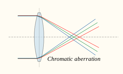
Chromatic aberration is caused by the dispersion of the lens material—the variation of its refractive index, n, with the wavelength of light. Since, from the formulae above, f is dependent upon n, it follows that light of different wavelengths is focused to different positions. Chromatic aberration of a lens is seen as fringes of colour around the image. It can be minimised by using an achromatic doublet (or achromat) in which two materials with differing dispersion are bonded together to form a single lens. This reduces the amount of chromatic aberration over a certain range of wavelengths, though it does not produce perfect correction. The use of achromats was an important step in the development of the optical microscope. An apochromat is a lens or lens system with even better chromatic aberration correction, combined with improved spherical aberration correction. Apochromats are much more expensive than achromats.

Different lens materials may also be used to minimise chromatic aberration, such as specialised coatings or lenses made from the crystal fluorite. This naturally occurring substance has the highest known Abbe number, indicating that the material has low dispersion.

Other types of aberration

Other kinds of aberration include field curvature, barrel and pincushion distortion, and astigmatism.

Aperture diffraction

Even if a lens is designed to minimize or eliminate the aberrations described above, the image quality is still limited by the diffraction of light passing through the lens' finite aperture. A diffraction-limited lens is one in which aberrations have been reduced to the point where the image quality is primarily limited by diffraction under the design conditions.

Compound lenses

Simple lenses are subject to the optical aberrations discussed above. In many cases these aberrations can be compensated for to a great extent by using a combination of simple lenses with complementary aberrations. A compound lens is a collection of simple lenses of different shapes and made of materials of different refractive indices, arranged one after the other with a common axis.

The simplest case is where lenses are placed in contact: if the lenses of focal lengths f1 and f2 are "thin", the combined focal length f of the lenses is given by

Since 1/f is the power of a lens, it can be seen that the powers of thin lenses in contact are additive.

If two thin lenses are separated in air by some distance d, the focal length for the combined system is given by

The distance from the front focal point of the combined lenses to the first lens is called the front focal length (FFL):

Similarly, the distance from the second lens to the rear focal point of the combined system is the back focal length (BFL):

As d tends to zero, the focal lengths tend to the value of f given for thin lenses in contact.

If the separation distance is equal to the sum of the focal lengths (d = f1 + f2), the FFL and BFL are infinite. This corresponds to a pair of lenses that transform a parallel (collimated) beam into another collimated beam. This type of system is called an afocal system, since it produces no net convergence or divergence of the beam. Two lenses at this separation form the simplest type of optical telescope. Although the system does not alter the divergence of a collimated beam, it does alter the width of the beam. The magnification of such a telescope is given by

which is the ratio of the output beam width to the input beam width. Note the sign convention: a telescope with two convex lenses (f1 > 0, f2 > 0) produces a negative magnification, indicating an inverted image. A convex plus a concave lens (f1 > 0 > f2) produces a positive magnification and the image is upright. For further information on simple optical telescopes, see Refracting telescope § Refracting telescope designs.

Non spherical types

An aspheric biconvex lens.

Cylindrical lenses have curvature along only one axis. They are used to focus light into a line, or to convert the elliptical light from a laser diode into a round beam. They are also used in motion picture anamorphic lenses.

Aspheric lenses have at least one surface that is neither spherical nor cylindrical. The more complicated shapes allow such lenses to form images with less aberration than standard simple lenses, but they are more difficult and expensive to produce. These were formerly complex to make and often extremely expensive, but advances in technology have greatly reduced the manufacturing cost for such lenses.

Close-up view of a flat Fresnel lens.

A Fresnel lens has its optical surface broken up into narrow rings, allowing the lens to be much thinner and lighter than conventional lenses. Durable Fresnel lenses can be molded from plastic and are inexpensive.

Lenticular lenses are arrays of microlenses that are used in lenticular printing to make images that have an illusion of depth or that change when viewed from different angles.

Bifocal lens has two or more, or a graduated, focal lengths ground into the lens.

A gradient index lens has flat optical surfaces, but has a radial or axial variation in index of refraction that causes light passing through the lens to be focused.

An axicon has a conical optical surface. It images a point source into a line along the optic axis, or transforms a laser beam into a ring.

Diffractive optical elements can function as lenses.

Superlenses are made from negative index metamaterials and claim to produce images at spatial resolutions exceeding the diffraction limit. The first superlenses were made in 2004 using such a metamaterial for microwaves. Improved versions have been made by other researchers. As of 2014 the superlens has not yet been demonstrated at visible or near-infrared wavelengths.

A prototype flat ultrathin lens, with no curvature has been developed.

Uses

A watch with a plano-convex lens over the date indicator

A single convex lens mounted in a frame with a handle or stand is a magnifying glass.

Lenses are used as prosthetics for the correction of refractive errors such as myopia, hypermetropia, presbyopia, and astigmatism. (See corrective lens, contact lens, eyeglasses, intraocular lens.) Most lenses used for other purposes have strict axial symmetry; eyeglass lenses are only approximately symmetric. They are usually shaped to fit in a roughly oval, not circular, frame; the optical centres are placed over the eyeballs; their curvature may not be axially symmetric to correct for astigmatism. Sunglasses' lenses are designed to attenuate light; sunglass lenses that also correct visual impairments can be custom made.

Other uses are in imaging systems such as monoculars, binoculars, telescopes, microscopes, cameras and projectors. Some of these instruments produce a virtual image when applied to the human eye; others produce a real image that can be captured on photographic film or an optical sensor, or can be viewed on a screen. In these devices lenses are sometimes paired up with curved mirrors to make a catadioptric system where the lens's spherical aberration corrects the opposite aberration in the mirror (such as Schmidt and meniscus correctors).

Convex lenses produce an image of an object at infinity at their focus; if the sun is imaged, much of the visible and infrared light incident on the lens is concentrated into the small image. A large lens creates enough intensity to burn a flammable object at the focal point. Since ignition can be achieved even with a poorly made lens, lenses have been used as burning-glasses for at least 2400 years. A modern application is the use of relatively large lenses to concentrate solar energy on relatively small photovoltaic cells, harvesting more energy without the need to use larger and more expensive cells.

Radio astronomy and radar systems often use dielectric lenses, commonly called a lens antenna to refract electromagnetic radiation into a collector antenna.

Lenses can become scratched and abraded. Abrasion-resistant coatings are available to help control this.

Science of photography

From Wikipedia, the free encyclopedia

The science of photography is the use of chemistry and physics in all aspects of photography. This applies to the camera, its lenses, physical operation of the camera, electronic camera internals, and the process of developing film in order to take and develop pictures properly.

Optics

Camera obscura

An image of a tree projected into a box through a pinhole.
Light enters a dark box through a small hole and creates an inverted image on the wall opposite the hole.

The fundamental technology of most photography, whether digital or analog, is the camera obscura effect and its ability to transform of a three dimensional scene into a two dimensional image. At its most basic, a camera obscura consists of a darkened box, with a very small hole in one side, which projects an image from the outside world onto the opposite side. This form is often referred to as a pinhole camera.

When aided by a lens, the hole in the camera doesn't have to be tiny to create a sharp and distinct image, and the exposure time can be decreased, which allows cameras to be handheld.

Lenses

A photographic lens is usually composed of several lens elements, which combine to reduce the effects of chromatic aberration, coma, spherical aberration, and other aberrations. A simple example is the three-element Cooke triplet, still in use over a century after it was first designed, but many current photographic lenses are much more complex.

Using a smaller aperture can reduce most, but not all aberrations. They can also be reduced dramatically by using an aspheric element, but these are more complex to grind than spherical or cylindrical lenses. However, with modern manufacturing techniques the extra cost of manufacturing aspherical lenses is decreasing, and small aspherical lenses can now be made by molding, allowing their use in inexpensive consumer cameras. Fresnel lenses are not common in photography are used in some cases due to their very low weight. The recently developed Fiber-coupled monocentric lens consists of spheres constructed of concentric hemispherical shells of different glasses tied to the focal plane by bundles of optical fibers. Monocentric lenses are also not used in cameras because the technology was just debuted in October 2013 at the Frontiers in Optics Conference in Orlando, Florida.

All lens design is a compromise between numerous factors, not excluding cost. Zoom lenses (i.e. lenses of variable focal length) involve additional compromises and therefore normally do not match the performance of prime lenses.

When a camera lens is focused to project an object some distance away onto the film or detector, the objects that are closer in distance, relative to the distant object, are also approximately in focus. The range of distances that are nearly in focus is called the depth of field. Depth of field generally increases with decreasing aperture diameter (increasing f-number). The unfocused blur outside the depth of field is sometimes used for artistic effect in photography. The subjective appearance of this blur is known as bokeh.

If the camera lens is focused at or beyond its hyperfocal distance, then the depth of field becomes large, covering everything from half the hyperfocal distance to infinity. This effect is used to make "focus free" or fixed-focus cameras.

Aberration

Aberrations are the blurring and distorting properties of an optical system. A high quality lens will produce a smaller amount of aberrations.

Spherical aberration occurs due to the increased refraction of light rays that occurs when rays strike a lens, or a reflection of light rays that occurs when rays strike a mirror near its edge in comparison with those that strike nearer the center. This is dependent on the focal length of a spherical lens and the distance from its center. It is compensated by designing a multi-lens system or by using an aspheric lens.

Chromatic aberration is caused by a lens having a different refractive index for different wavelengths of light and the dependence of the optical properties on color. Blue light will generally bend more than red light. There are higher order chromatic aberrations, such as the dependence of magnification on color. Chromatic aberration is compensated by using a lens made out of materials carefully designed to cancel out chromatic aberrations.

Curved focal surface is the dependence of the first order focus on the position on the film or CCD. This can be compensated with a multiple lens optical design, but curving the film has also been used.

Focus

This subject is in sharp focus while the distant background is unfocused

Focus is the tendency for light rays to reach the same place on the image sensor or film, independent of where they pass through the lens. For clear pictures, the focus is adjusted for distance, because at a different object distance the rays reach different parts of the lens with different angles. In modern photography, focusing is often accomplished automatically.

The autofocus system in modern SLRs use a sensor in the mirrorbox to measure contrast. The sensor's signal is analyzed by an application-specific integrated circuit (ASIC), and the ASIC tries to maximize the contrast pattern by moving lens elements. The ASICs in modern cameras also have special algorithms for predicting motion, and other advanced features.

Diffraction limit

Since light propagates as waves, the patterns it produces on the film are subject to the wave phenomenon known as diffraction, which limits the image resolution to features on the order of several times the wavelength of light. Diffraction is the main effect limiting the sharpness of optical images from lenses that are stopped down to small apertures (high f-numbers), while aberrations are the limiting effect at large apertures (low f-numbers). Since diffraction cannot be eliminated, the best possible lens for a given operating condition (aperture setting) is one that produces an image whose quality is limited only by diffraction. Such a lens is said to be diffraction limited.

The diffraction-limited optical spot size on the CCD or film is proportional to the f-number (about equal to the f-number times the wavelength of light, which is near 0.0005 mm), making the overall detail in a photograph proportional to the size of the film, or CCD divided by the f-number. For a 35 mm camera with f/11, this limit corresponds to about 6,000 resolution elements across the width of the film (36 mm / (11 * 0.0005 mm) = 6,500.

The finite spot size caused by diffraction can also be expressed as a criterion for distinguishing distant objects: two distant point sources can only produce separate images on the film or sensor if their angular separation exceeds the wavelength of light divided by the width of the open aperture of the camera lens.

Chemical processes

Gelatin silver

The gelatin silver process is the most commonly used chemical process in black-and-white photography, and is the fundamental chemical process for modern analog color photography. As such, films and printing papers available for analog photography rarely rely on any other chemical process to record an image.

Daguerreotypes

Daguerreotype (/dəˈɡɛər(i.)əˌtp, -(i.)-/ ; French: daguerréotype) was the first publicly available photographic process; it was widely used during the 1840s and 1850s. "Daguerreotype" also refers to an image created through this process.

Collodion process and the ambrotype

The collodion process is an early photographic process. The collodion process, mostly synonymous with the "collodion wet plate process", requires the photographic material to be coated, sensitized, exposed and developed within the span of about fifteen minutes, necessitating a portable darkroom for use in the field. Collodion is normally used in its wet form, but can also be used in dry form, at the cost of greatly increased exposure time. The latter made the dry form unsuitable for the usual portraiture work of most professional photographers of the 19th century. The use of the dry form was therefore mostly confined to landscape photography and other special applications where minutes-long exposure times were tolerable.

Cyanotypes

Cyanotype is a photographic printing process that produces a cyan-blue print. Engineers used the process well into the 20th century as a simple and low-cost process to produce copies of drawings, referred to as blueprints. The process uses two chemicals: ferric ammonium citrate and potassium ferricyanide.

Platinum and palladium processes

Platinum prints, also called platinotypes, are photographic prints made by a monochrome printing process involving platinum.

Gum bichromate

Gum bichromate is a 19th-century photographic printing process based on the light sensitivity of dichromates. It is capable of rendering painterly images from photographic negatives. Gum printing is traditionally a multi-layered printing process, but satisfactory results may be obtained from a single pass. Any color can be used for gum printing, so natural-color photographs are also possible by using this technique in layers.

C-prints and color film

A chromogenic print, also known as a C-print or C-type print, a silver halide print, or a dye coupler print, is a photographic print made from a color negative, transparency or digital image, and developed using a chromogenic process. They are composed of three layers of gelatin, each containing an emulsion of silver halide, which is used as a light-sensitive material, and a different dye coupler of subtractive color which together, when developed, form a full-color image.

Digital sensors

An image sensor or imager is a sensor that detects and conveys information used to make an image. It does so by converting the variable attenuation of light waves (as they pass through or reflect off objects) into signals, small bursts of current that convey the information. The waves can be light or other electromagnetic radiation. Image sensors are used in electronic imaging devices of both analog and digital types, which include digital cameras, camera modules, camera phones, optical mouse devices, medical imaging equipment, night vision equipment such as thermal imaging devices, radar, sonar, and others. As technology changes, electronic and digital imaging tends to replace chemical and analog imaging.

Practical applications

Law of reciprocity

Exposure ∝ Aperture Area × Exposure Time × Scene Luminance

The law of reciprocity describes how light intensity and duration trade off to make an exposure—it defines the relationship between shutter speed and aperture, for a given total exposure. Changes to any of these elements are often measured in units known as "stops"; a stop is equal to a factor of two.

Halving the amount light exposing the film can be achieved either by:

  1. Closing the aperture by one stop
  2. Decreasing the shutter time (increasing the shutter speed) by one stop
  3. Cutting the scene lighting by half

Likewise, doubling the amount of light exposing the film can be achieved by the opposite of one of these operations.

The luminance of the scene, as measured on a reflected light meter, also affects the exposure proportionately. The amount of light required for proper exposure depends on the film speed; which can be varied in stops or fractions of stops. With either of these changes, the aperture or shutter speed can be adjusted by an equal number of stops to get to a suitable exposure.

Light is most easily controlled through the use of the camera's aperture (measure in f-stops), but it can also be regulated by adjusting the shutter speed. Using faster or slower film is not usually something that can be done quickly, at least using roll film. Large format cameras use individual sheets of film and each sheet could be a different speed. Also, if you're using a larger format camera with a polaroid back, you can switch between backs containing different speed polaroids. Digital cameras can easily adjust the film speed they are simulating by adjusting the exposure index, and many digital cameras can do so automatically in response to exposure measurements.

For example, starting with an exposure of 1/60 at f/16, the depth-of-field could be made shallower by opening up the aperture to f/4, an increase in exposure of 4 stops. To compensate, the shutter speed would need to be increased as well by 4 stops, that is, adjust exposure time down to 1/1000. Closing down the aperture limits the resolution due to the diffraction limit.

The reciprocity law specifies the total exposure, but the response of a photographic material to a constant total exposure may not remain constant for very long exposures in very faint light, such as photographing a starry sky, or very short exposures in very bright light, such as photographing the sun. This is known as reciprocity failure of the material (film, paper, or sensor).

Motion blur

Motion blur is caused when either the camera or the subject moves during the exposure. This causes a distinctive streaky appearance to the moving object or the entire picture (in the case of camera shake).

Motion blur of a background while following the subject

Motion blur can be used artistically to create the feeling of speed or motion, as with running water. An example of this is the technique of "panning", where the camera is moved so it follows the subject, which is usually fast moving, such as a car. Done correctly, this will give an image of a clear subject, but the background will have motion blur, giving the feeling of movement. This is one of the more difficult photographic techniques to master, as the movement must be smooth, and at the correct speed. A subject that gets closer or further away from the camera may further cause focusing difficulties.

Light trails

Light trails are another photographic effect where motion blur is used. Photographs of the lines of light visible in long exposure photos of roads at night are one example of the effect. This is caused by the cars moving along the road during the exposure. The same principle is used to create star trail photographs.

Generally, motion blur is something that is to be avoided, and this can be done in several different ways. The simplest way is to limit the shutter time so that there is very little movement of the image during the time the shutter is open. At longer focal lengths, the same movement of the camera body will cause more motion of the image, so a shorter shutter time is needed. A commonly cited rule of thumb is that the shutter speed in seconds should be about the reciprocal of the 35 mm equivalent focal length of the lens in millimeters. For example, a 50 mm lens should be used at a minimum speed of 1/50 sec, and a 300 mm lens at 1/300 of a second. This can cause difficulties when used in low light scenarios, since exposure also decreases with shutter time.

High speed photography uses very short exposures to prevent blurring of fast moving subjects

Motion blur due to subject movement can usually be prevented by using a faster shutter speed. The exact shutter speed will depend on the speed at which the subject is moving. For example, a very fast shutter speed will be needed to "freeze" the rotors of a helicopter, whereas a slower shutter speed will be sufficient to freeze a runner.

A tripod may be used to avoid motion blur due to camera shake. This will stabilize the camera during the exposure. A tripod is recommended for exposure times more than about 1/15 seconds. There are additional techniques which, in conjunction with use of a tripod, ensure that the camera remains very still. These may employ use of a remote actuator, such as a cable release or infrared remote switch to activate the shutter, so as to avoid the movement normally caused when the shutter release button is pressed directly. The use of a "self timer" (a timed release mechanism that automatically trips the shutter release after an interval of time) can serve the same purpose. Most modern single-lens reflex camera (SLR) have a mirror lock-up feature that eliminates the small amount of shake produced by the mirror flipping up.

Film grain resolution

Strong grain on ISO400 negative film, pushed to ISO1600.

Black-and-white film has a "shiny" side and a "dull" side. The dull side is the emulsion, a gelatin that suspends an array of silver halide crystals. These crystals contain silver grains that determine how sensitive the film is to light exposure, and how fine or grainy the negative the print will look. Larger grains mean faster exposure but a grainier appearance; smaller grains are finer looking but take more exposure to activate. The graininess of film is represented by its ISO factor; generally a multiple of 10 or 100. Lower numbers produce finer grain but slower film, and vice versa.

Contribution to noise (grain)

Quantum efficiency

Light comes in particles and the energy of a light-particle (the photon) is the frequency of the light times Planck's constant. A fundamental property of any photographic method is how it collects the light on its photographic plate or electronic detector.

CCDs and other photodiodes

Photodiodes are back-biased semiconductor diodes, in which an intrinsic layer with very few charge carriers prevents electric currents from flowing. Depending on the material, photons have enough energy to raise one electron from the upper full band to the lowest empty band. The electron and the "hole", or the empty space where it was, are then free to move in the electric field and carry current, which can be measured. The fraction of incident photons that produce carrier pairs depends largely on the semiconductor material.

Photomultiplier tubes

Photomultiplier tubes are vacuum phototubes that amplify light by accelerating the photoelectrons to knock more electrons free from a series of electrodes. They are among the most sensitive light detectors but are not well suited to photography.

Aliasing

Aliasing can occur in optical and chemical processing, but it is more common and easily understood in digital processing. It occurs whenever an optical or digital image is sampled or re-sampled at a rate which is too low for its resolution. Some digital cameras and scanners have anti-aliasing filters to reduce aliasing by intentionally blurring the image to match the sampling rate. It is common for film developing equipment used to make prints of different sizes to increase the graininess of the smaller size prints by aliasing.

It is usually desirable to suppress both noises such as grain and details of the real object that are too small to be represented at the sampling rate.

Green wall

From Wikipedia, the free encyclopedia
https://en.wikipedia.org/wiki/Green_wall

Detail of Patrick Blanc's exterior green wall of the Musée du Quai Branly (image 2012)
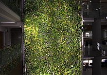
An indoor green wall at the University of Ottawa

A green wall is a vertical built structure intentionally covered by vegetation. Green walls include a vertically applied growth medium such as soil, substitute substrate, or hydroculture felt; as well as an integrated hydration and fertigation delivery system. They are also referred to as living walls or vertical gardens, and widely associated with the delivery of many beneficial ecosystem services.

Green walls differ from the more established vertical greening typology of 'green facades' as they have the growth medium supported on the vertical face of the host wall (as described below), while green facades have the growth medium only at the base (either in a container or as a ground bed). Green facades typically support climbing plants that climb up the vertical face of the host wall, while green walls can accommodate a variety of plant species. Green walls may be implanted indoors or outdoors; as freestanding installations or attached to existing host walls; and applied in a variety of sizes.

Stanley Hart White, a Professor of Landscape Architecture at the University of Illinois from 1922 to 1959, patented a 'vegetation-Bearing Architectonic Structure and System' in 1938, though his invention did not progress beyond prototypes in his backyard in Urbana, Illinois. The popularising of green walls is often credited to Patrick Blanc, a French botanist specialised in tropical forest undergrowth. He worked with architect Adrien Fainsilber and engineer Peter Rice to implement the first successful large indoor green wall or Mur Vegetal in 1986 at the Cité des Sciences et de l'Industrie in Paris, and has since been involved with the design and implementation of a number of notable installations (e.g. Musée du quai Branly, collaborating with architect Jean Nouvel).

Green walls have seen a surge in popularity in recent times. An online database provided by greenroof.com for example had reported 80% of the 61 large-scale outdoor green walls listed as constructed after 2009, with 93% after 2007. Many notable green walls have been installed at institutional buildings and public places, with both outdoor and indoor installations gaining significant attention. As of 2015, the largest green wall is said to cover 2,700 square meters (29,063 square feet) and is located at the Los Cabos International Convention Centre designed by Mexican architect Fernando Romero.

Media types

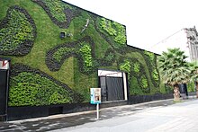
Green wall at the Universidad del Claustro de Sor Juana in the historic center of Mexico City
A wall of living plants designed by Patrick Blanc at Caixa Forum near Atocha station, Madrid
A green wall (mat media) in a children's museum, Kitchener, Ontario, Canada

Green walls are often constructed of modular panels that hold a growing medium and can be categorized according to the type of growth media used: loose media, mat media, and structural media.

Media Free

Media Free tillandsia green wall designed by Lloyd Godman, East Melbourne, Australia.
Media Free tillandsia green wall structural cross section. Designed by Lloyd Godman, East Melbourne, Australia.

Media Free systems utilize a method of selecting plant species which are best suited to the climate where the green wall is located, and as a result, these media free systems do not require soil substrates, fertilizers, or reticulated watering systems. These Media Free systems result in green walls which are considerably lighter than other methods, and also require significantly less maintenance, while the risk of liquid migration into adjoining structural walls is eliminated. The plant species which can be used in Media Free systems varies depending on the location of the planned green wall. Xeric plants, such as Tillandsias, can be used because they absorb available atmospheric water and nutrients via trichome leaf cells, and their roots have developed to hold onto a support structure, unlike other plants which use their roots as a medium to absorb nutrients. The other benefit of Tillandsias within a Media Free system is that these plants use a crassulacean acid metabolism to photosynthesize, and they have evolved to withstand long periods of heat and drought, and as a result, these plants grow slowly and require minimal maintenance. These Media Free green walls often use a structural steel frame that is infilled with wire mesh, which is then attached to the façade of the structure, and plants are individually attached to this wire mesh. These frames are offset from the supporting structure to allow airflow between the green wall and the supporting structure, and this offset results in additional cooling to the adjoining building. Every three-to-five-years, any additional plant growth can be harvested to reduce weight, and these plant pups can be utilized for additional green walls. As long as suitable species are matched to the climate of the green wall's location, then potential plant losses across any three-to-five-year period is minor. As there is no watering system involved this method eliminates potential mold, algae and moss problems that can plague other systems. Because of the lack of media and water, these screens can also be installed horizontally, and the first of these screens ever installed was for a 2023 installation on the rooftop of the City of Melbourne's Council House 2 building.

Freestanding media

Freestanding media are portable living walls that are flexible for interior landscaping and are considered to have many biophilic design benefits. Zauben living walls are designed with hydroponic technology that conserves 75% more water than plants grown in soil, self-irrigates, and includes moisture sensors.

Loose media

Loose medium walls tend to be "soil-on-a-shelf" or "soil-in-a-bag" type systems. Loose medium systems have their soil packed into a shelf or bag and are then installed onto the wall. These systems require their media to be replaced at least once a year on exteriors and approximately every two years on interiors. Loose soil systems are not well suited for areas with any seismic activity. Most importantly, because these systems can easily have their medium blown away by wind-driven rain or heavy winds, these should not be used in applications over 2.5 m high. There are some systems in Asia that have solved the loose media erosion problem by use of shielding systems to hold the media within the green wall system even when soil liquefaction occurs under seismic load. In these systems, the plants can still up-root themselves in the liquified soil under seismic load, and therefore it is required that the plants be secured to the system to prevent them from falling from the wall. Loose-soil systems without physical media erosion systems are best suited for the home gardener where occasional replanting is desired from season to season or year to year. Loose-soil systems with physical media erosion systems are well suited for all green wall applications.

Mat media

Mat type systems tend to be either coir fiber or felt mats. Mat media are quite thin, even in multiple layers, and as such cannot support vibrant root systems of mature plants for more than three to five years before the roots overtake the mat and water is not able to adequately wick through the mats. The method of reparation of these systems is to replace large sections of the system at a time by cutting the mat out of the wall and replacing it with new mat. This process compromises the root structures of the neighboring plants on the wall and often kills many surrounding plants in the reparation process. These systems are best used on the interior of a building and are a good choice in areas with low seismic activity and small plants that will not grow to a weight that could rip the mat apart under their own weight over time. It is important to note that mat systems are particularly water inefficient and often require constant irrigation due to the thin nature of the medium and its inability to hold water and provide a buffer for the plant roots. This inefficiency often requires that these systems have a water re-circulation system put into place at an additional cost. Mat media are better suited for small installations no more than eight feet in height where repairs are easily completed.

Sheet media

Semi-open cell polyurethane sheet media utilising an egg crate pattern has successfully been used in recent years for both outdoor roof gardens and vertical walls. The water holding capacity of these engineered polyurethanes vastly exceeds that of coir and felt based systems. Polyurethanes do not biodegrade, and hence stay viable as an active substrate for 20+ years. Vertical wall systems utilising polyurethane sheeting typically employ a sandwich construction where a water proof membrane is applied to the back, the polyurethane sheeting (typically two sheets with irrigation lines in between) is laid and then a mesh or anchor braces/bars secure the assembly to the wall. Pockets are cut into the face of the first urethane sheet into which plants are inserted. Soil is typically removed from the roots of any plants prior to insertion into the urethane mattress substrate. A flaked or chopped noodle version of the same polyurethane material can also be added to existing structural media mixes to boost water retention.

Structural media

The Green Wall in Sutton High Street, Sutton, Greater London

Structural media are growth medium "blocks" that are not loose, nor mats, but which incorporate the best features of both into a block that can be manufactured into various sizes, shapes and thicknesses. These media have the advantage that they do not break down for 10 to 15 years, can be made to have a higher or lower water holding capacity depending on the plant selection for the wall, can have their pH and EC's customized to suit the plants, and are easily handled for maintenance and replacement.

There is also some discussion involving "active" living walls. An active living wall actively pulls or forces air through the plants le quality to the point that the installation of other air quality filtration systems can be removed to provide a cost-savings. Therefore, the added cost of design, planning and implementation of an active living wall is still in question. With further research and UL standards to support the air quality data from the living wall, building code may one day allow for our buildings to have their air filtered by plants.

The area of air quality and plants is continuing to be researched. Early studies in this area include NASA studies performed in the 1970s and 1980s by B. C. Wolverton. There was also a study performed at the University of Guelph by Alan Darlington. Other research has shown the effect the plants have on the health of office workers.

Function

An indoor green wall in an office in Hong Kong

Green walls are found most often in urban environments where the plants reduce overall temperatures of the building. "The primary cause of heat build-up in cities is insolation, the absorption of solar radiation by roads and buildings in the city and the storage of this heat in the building material and its subsequent re-radiation. Plant surfaces however, as a result of transpiration, do not rise more than 4–5 °C above the ambient and are sometimes cooler."

Living walls may also be a means for water reuse. The plants may purify slightly polluted water (such as greywater) by absorbing the dissolved nutrients. Bacteria mineralize the organic components to make them available to the plants. A study is underway at the Bertschi School in Seattle, Washington, using a GSky Pro Wall system, however, no publicly available data on this is available at this time.

Living walls are particularly suitable for cities, as they allow good use of available vertical surface areas. They are also suitable in arid areas, as the circulating water on a vertical wall is less likely to evaporate than in horizontal gardens.

The living wall could also function for urban agriculture, urban gardening, or for its beauty as art. It is sometimes built indoors to help alleviate sick building syndrome.

A green wall in Longwood Gardens in Pennsylvania.

Living walls are also acknowledged for remediation of poor air quality, both to internal and external areas.

Green walls provide an additional layer of insulation that can protect buildings from heavy rainwater which leads to management of heavy storm water and provides thermal mass. They also help reduce the temperature of a building because vegetation absorbs large amounts of solar radiation. This can reduce energy demands and cleanse the air from VOC’s (Volatile Organic Compounds) released by paints, furniture, and adhesives. Off-gassing from VOCs can cause headaches, eye irritation, and airway irritation and internal air pollution. Green walls can also purify the air from mould growth in building interiors that can cause asthma and allergies. Vegetation in green walls can help with the mitigation of the heat island effect and contribute to urban biodiversity.

Indoor green walls can have a therapeutic effect from exposure to vegetation. The aesthetic feel and visual appearance of green walls are other examples of the benefits - but also affects the indoor climate with reduced CO2 level, noise level and air pollution abatement. However, to have the optimal effect on the indoor climate it is important that the plants in the green wall has the best conditions for growth, both when talking about watering, fertilizing and the right amount of light. To have the best result on all of the aforementioned, some green wall systems has special and patented technologies that is developed to the benefit of the plants.

Another example in urban areas is green walls provide acoustic protection and reduces the noise through sound absorption.

Thomas Pugh, a biogeochemist at the Karlsruhe Institute of Technology in Germany, created a computer model of a green wall with a broad selection of vegetation. The study showed results of the green wall absorbing nitrogen dioxide and particulate matter. In street canyons where polluted air is trapped, green walls can absorb the polluted air and purify the streets.

Plants

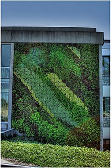
Green wall the Simon Fraser University, Burnaby, British Columbia, Canada.

List of plants best suited for Media Free gardens

List of herbs best suited for green facades

Edible plants best suited for green facades

Plants for sun

Plants for shade

Inequality (mathematics)

From Wikipedia, the free encyclopedia https://en.wikipedia.org/wiki/Inequality...