Search This Blog

Monday, August 5, 2024

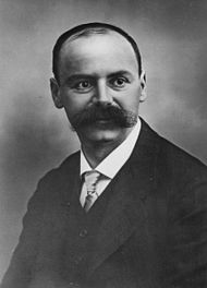
Karl Schwarzschild

From Wikipedia, the free encyclopedia
 
Karl Schwarzschild
Born9 October 1873
Died11 May 1916 (aged 42)
Potsdam, German Empire
Alma materLudwig Maximilian University of Munich
University of Strasbourg
Scientific career
FieldsPhysics
Astronomy
Doctoral advisorHugo von Seeliger

Military career
Allegiance German Empire
Service/branchImperial German Army
Years of service1914–1916
RankLieutenant
Battles/warsWorld War I

Karl Schwarzschild (German: [kaːl ˈʃvaːtsʃɪlt] ; 9 October 1873 – 11 May 1916) was a German physicist and astronomer.

Schwarzschild provided the first exact solution to the Einstein field equations of general relativity, for the limited case of a single spherical non-rotating mass, which he accomplished in 1915, the same year that Einstein first introduced general relativity. The Schwarzschild solution, which makes use of Schwarzschild coordinates and the Schwarzschild metric, leads to a derivation of the Schwarzschild radius, which is the size of the event horizon of a non-rotating black hole.

Schwarzschild accomplished this while serving in the German army during World War I. He died the following year from the autoimmune disease pemphigus, which he developed while at the Russian front.[2][3] Various forms of the disease particularly affect people of Ashkenazi Jewish origin.

Asteroid 837 Schwarzschilda is named in his honour, as is the large crater Schwarzschild, on the far side of the Moon.

Life

Karl Schwarzschild was born on 9 October 1873 in Frankfurt on Main, the eldest of six boys and one girl, to Jewish parents. His father was active in the business community of the city, and the family had ancestors in Frankfurt from the sixteenth century onwards. The family owned two fabric stores in Frankfurt. His brother Alfred became a painter. The young Schwarzschild attended a Jewish primary school until 11 years of age and then the Lessing-Gymnasium (secondary school). He received an all-encompassing education, including subjects like Latin, Ancient Greek, music and art, but developed a special interest in astronomy early on. In fact he was something of a child prodigy, having two papers on binary orbits (celestial mechanics) published before the age of sixteen.

After graduation in 1890, he attended the University of Strasbourg to study astronomy. After two years he transferred to the Ludwig Maximilian University of Munich where he obtained his doctorate in 1896 for a work on Henri Poincaré's theories.

From 1897, he worked as assistant at the Kuffner Observatory in Vienna. His work here concentrated on the photometry of star clusters and laid the foundations for a formula linking the intensity of the starlight, exposure time, and the resulting contrast on a photographic plate. An integral part of that theory is the Schwarzschild exponent (astrophotography). In 1899, he returned to Munich to complete his Habilitation.

From 1901 until 1909, he was a professor at the prestigious Göttingen Observatory within the University of Göttingen, where he had the opportunity to work with some significant figures, including David Hilbert and Hermann Minkowski. Schwarzschild became the director of the observatory. He married Else Rosenbach, a great-granddaughter of Friedrich Wöhler and daughter of a professor of surgery at Göttingen, in 1909. Later that year they moved to Potsdam, where he took up the post of director of the Astrophysical Observatory. This was then the most prestigious post available for an astronomer in Germany.

Schwarzschild, third from left in the automobile; possibly during the Fifth Conference of the International Union for Co-operation in Solar Research, held in Bonn, Germany
Karl Schwarzschild's grave at Stadtfriedhof (Göttingen)
Schwarzschild at the Fourth Conference International Union for Cooperation in Solar Research at Mount Wilson Observatory, 1910

From 1912, Schwarzschild was a member of the Prussian Academy of Sciences.

At the outbreak of World War I in 1914, Schwarzschild volunteered for service in the German army despite being over 40 years old. He served on both the western and eastern fronts, specifically helping with ballistic calculations and rising to the rank of second lieutenant in the artillery.

While serving on the front in Russia in 1915, he began to suffer from pemphigus, a rare and painful autoimmune skin-disease. Nevertheless, he managed to write three outstanding papers, two on the theory of relativity and one on quantum theory. His papers on relativity produced the first exact solutions to the Einstein field equations, and a minor modification of these results gives the well-known solution that now bears his name — the Schwarzschild metric.

In March 1916, Schwarzschild left military service because of his illness and returned to Göttingen. Two months later, on May 11, 1916, his struggle with pemphigus may have led to his death at the age of 42.

He rests in his family grave at the Stadtfriedhof Göttingen.

With his wife Else he had three children:

Work

Thousands of dissertations, articles, and books have since been devoted to the study of Schwarzschild's solutions to the Einstein field equations. However, although his best known work lies in the area of general relativity, his research interests were extremely broad, including work in celestial mechanics, observational stellar photometry, quantum mechanics, instrumental astronomy, stellar structure, stellar statistics, Halley's comet, and spectroscopy.

Some of his particular achievements include measurements of variable stars, using photography, and the improvement of optical systems, through the perturbative investigation of geometrical aberrations.

Physics of photography

While at Vienna in 1897, Schwarzschild developed a formula, now known as the Schwarzschild law, to calculate the optical density of photographic material. It involved an exponent now known as the Schwarzschild exponent, which is the in the formula:

(where is optical density of exposed photographic emulsion, a function of , the intensity of the source being observed, and , the exposure time, with a constant). This formula was important for enabling more accurate photographic measurements of the intensities of faint astronomical sources.

Electrodynamics

According to Wolfgang Pauli, Schwarzschild is the first to introduce the correct Lagrangian formalism of the electromagnetic field  as

where are the electric and applied magnetic fields, is the vector potential and is the electric potential.

He also introduced a field free variational formulation of electrodynamics (also known as "action at distance" or "direct interparticle action") based only on the world line of particles as 

where are the world lines of the particle, the (vectorial) arc element along the world line. Two points on two world lines contribute to the Lagrangian (are coupled) only if they are a zero Minkowskian distance (connected by a light ray), hence the term . The idea was further developed by Hugo Tetrode and Adriaan Fokker in the 1920s and John Archibald Wheeler and Richard Feynman in the 1940s  and constitutes an alternative but equivalent formulation of electrodynamics.

Relativity

The Kepler problem in general relativity, using the Schwarzschild metric

Einstein himself was pleasantly surprised to learn that the field equations admitted exact solutions, because of their prima facie complexity, and because he himself had produced only an approximate solution. Einstein's approximate solution was given in his famous 1915 article on the advance of the perihelion of Mercury. There, Einstein used rectangular coordinates to approximate the gravitational field around a spherically symmetric, non-rotating, non-charged mass. Schwarzschild, in contrast, chose a more elegant "polar-like" coordinate system and was able to produce an exact solution which he first set down in a letter to Einstein of 22 December 1915, written while he was serving in the war stationed on the Russian front. He concluded the letter by writing: "As you see, the war is kindly disposed toward me, allowing me, despite fierce gunfire at a decidedly terrestrial distance, to take this walk into this your land of ideas." In 1916, Einstein wrote to Schwarzschild on this result:

I have read your paper with the utmost interest. I had not expected that one could formulate the exact solution of the problem in such a simple way. I liked very much your mathematical treatment of the subject. Next Thursday I shall present the work to the Academy with a few words of explanation.

Boundary region of Schwarzschild interior and exterior solution

Schwarzschild's second paper, which gives what is now known as the "Inner Schwarzschild solution" (in German: "innere Schwarzschild-Lösung"), is valid within a sphere of homogeneous and isotropic distributed molecules within a shell of radius r=R. It is applicable to solids; incompressible fluids; the sun and stars viewed as a quasi-isotropic heated gas; and any homogeneous and isotropic distributed gas.

Schwarzschild's first (spherically symmetric) solution does not contain a coordinate singularity on a surface that is now named after him. In his coordinates, this singularity lies on the sphere of points at a particular radius, called the Schwarzschild radius:

where G is the gravitational constant, M is the mass of the central body, and c is the speed of light in vacuum. In cases where the radius of the central body is less than the Schwarzschild radius, represents the radius within which all massive bodies, and even photons, must inevitably fall into the central body (ignoring quantum tunnelling effects near the boundary). When the mass density of this central body exceeds a particular limit, it triggers a gravitational collapse which, if it occurs with spherical symmetry, produces what is known as a Schwarzschild black hole. This occurs, for example, when the mass of a neutron star exceeds the Tolman–Oppenheimer–Volkoff limit (about three solar masses).

Maximum power point tracking

From Wikipedia, the free encyclopedia
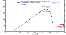
Power/Voltage-curve of a partially shaded PV system, with marked local and global MPP

Maximum power point tracking (MPPT), or sometimes just power point tracking (PPT), is a technique used with variable power sources to maximize energy extraction as conditions vary. The technique is most commonly used with photovoltaic (PV) solar systems but can also be used with wind turbines, optical power transmission and thermophotovoltaics.

PV solar systems have varying relationships to inverter systems, external grids, battery banks, and other electrical loads. The central problem addressed by MPPT is that the efficiency of power transfer from the solar cell depends on the amount of available sunlight, shading, solar panel temperature and the load's electrical characteristics. As these conditions vary, the load characteristic (impedance) that gives the highest power transfer changes. The system is optimized when the load characteristic changes to keep power transfer at highest efficiency. This optimal load characteristic is called the maximum power point (MPP). MPPT is the process of adjusting the load characteristic as the conditions change. Circuits can be designed to present optimal loads to the photovoltaic cells and then convert the voltage, current, or frequency to suit other devices or systems.

Solar cells' non-linear relationship between temperature and total resistance can be analyzed based on the Current-voltage (I-V) curve and the power-voltage (P-V) curves. MPPT samples cell output and applies the proper resistance (load) to obtain maximum power. MPPT devices are typically integrated into an electric power converter system that provides voltage or current conversion, filtering, and regulation for driving various loads, including power grids, batteries, or motors. Solar inverters convert DC power to AC power and may incorporate MPPT.

The power at the MPP (Pmpp) is the product of the MPP voltage (Vmpp) and MPP current (Impp).

In general, the P-V curve of a partially shaded solar array can have multiple peaks, and some algorithms can get stuck in a local maximum rather than the global maximum of the curve.

Background

Photovoltaic solar cell I-V curves where a line intersects the knee of the curves where the maximum power transfer point is located.

Photovoltaic cells have a complex relationship between their operating environment and the power they produce. The nonlinear I-V curve characteristic of a given cell in specific temperature and insolation conditions can be functionally characterized by a fill factor (FF). Fill factor is defined as the ratio of the maximum power from the cell to the product of open circuit voltage Voc and short-circuit current Isc. Tabulated data is often used to estimate the maximum power that a cell can provide with an optimal load under given conditions:

.

For most purposes, FF, Voc, and Isc are enough information to give a useful approximate view of the cell's electrical behavior under typical conditions.

For any given set of conditions, cells have a single operating point where the values of the current (I) and voltage (V) of the cell allow maximum power output. These values correspond to a particular load resistance, which is equal to V / I as specified by Ohm's law. The power P is given by P=V I.

A photovoltaic cell, for the majority of its useful curve, acts as a constant current source. However, at a photovoltaic cell's MPP region, its curve has an approximately inverse exponential relationship between current and voltage. From basic circuit theory, the power delivered to a device is optimized (MPP) where the derivative (graphically, the slope) dI/dV of the I-V curve is equal and opposite the I/V ratio (where dP/dV=0) and corresponds to the "knee" of the curve.

A load with resistance R=V/I equal to the reciprocal of this value draws the maximum power from the device. This is sometimes called the 'characteristic resistance' of the cell. This is a dynamic quantity that changes depending on the level of illumination, as well as other factors such as temperature and cell condition. Lower or higher resistance reduces power output. Maximum power point trackers utilize control circuits or logic to identify this point.

Power-voltage (P-V) curve

If a full power-voltage (P-V) curve is available, then the maximum power point can be obtained using a bisection method.

Implementation

When directly connecting a load to cell, the operating point of the panel is rarely at peak power. The impedance seen by the panel determines its operating point. Setting the impedance correctly achieves peak power. Since panels are DC devices, DC-DC converters transform the impedance of one circuit (source) to the other circuit (load). Changing the duty ratio of the DC-DC converter changes the impedance (duty ratio) seen by the cell. The I-V curve of the panel can be considerably affected by atmospheric conditions such as irradiance and temperature.

MPPT algorithms frequently sample panel voltages and currents, then adjust the duty ratio accordingly. Microcontrollers implement the algorithms. Modern implementations often utilize more sophisticated computers for analytics and load forecasting.

Classification

Controllers can follow several strategies to optimize power output. MPPTs may switch among multiple algorithms as conditions dictate.

Perturb and observe

In this method the controller adjusts the voltage from the array by a small amount and measures power; if the power increases, further adjustments in that direction are tried until power no longer increases. This is called perturb and observe (P&O) and is most common, although this method can cause power output to oscillate. It is also referred to as a hill climbing method, because it depends on the rise of the curve of power against voltage below the maximum power point, and the fall above that point. Perturb and observe is the most commonly used method due to its ease of implementation. Perturb and observe method may result in top-level efficiency, provided that a proper predictive and adaptive hill climbing strategy is adopted.

Incremental conductance

In this method, the controller measures incremental current and voltage changes to predict the effect of a voltage change. This method requires more computation in the controller, but can track changing conditions more rapidly than P&O. Power output does not oscillate. It utilizes the incremental conductance () of the photovoltaic array to compute the sign of the change in power with respect to voltage (). The incremental conductance method computes MPP by comparison of the incremental conductance () to the array conductance (). When these two are the same (), the output voltage is the MPP voltage. The controller maintains this voltage until the irradiation changes and the process is repeated.

The incremental conductance method is based on the observation that at MPP, , and that . The current from the array can be expressed as a function of the voltage:

.

Therefore, . Setting this equal to zero yields: . Therefore, MPP is achieved when the incremental conductance is equal to the negative of the instantaneous conductance. The power-voltage curve characteristic shows that: when the voltage is smaller than MPP, , so ; when the voltage is bigger than MPP, or . Thus, a tracker can know where it is on the power-voltage curve by calculating the relation of the change of current/voltage and the current voltage themselves.

Current sweep

The current sweep method uses a sweep waveform for the array current such that the I-V characteristic of the PV array is obtained and updated at fixed time intervals. MPP voltage can then be computed from the characteristic curve at the same intervals.

Constant voltage

Constant voltage methods include one in which the output voltage is regulated to a constant value under all conditions and one in which the output voltage is regulated based on a constant ratio to the measured open circuit voltage (). The latter technique may also be labeled the "open voltage" method. If the output voltage is held constant, there is no attempt to track MPP, so it is not strictly a MPPT technique, though it does function in cases when MPP tracking tends to fail, and thus it is sometimes used supplementally. In the open voltage method, power delivery is momentarily interrupted and the open-circuit voltage with zero current is measured. The controller then resumes operation with the voltage controlled at a fixed ratio, such as 0.76, of the open-circuit voltage . This is usually a value that has been predetermined to be the MPP, either empirically or based on modelling, for expected operating conditions. The array's operating point is thus kept near MPP by regulating the array voltage and matching it to the fixed reference voltage . The value of may be chosen to give optimal performance relative to other factors as well as the MPP, but the central idea is that is determined as a ratio to . One of the inherent approximations in the method is that the ratio of MPP voltage to is only approximately constant, so it leaves room for further possible optimization.

Temperature method

This method estimates the MPP voltage () by measuring the temperature of the solar module and comparing it against a reference. Since changes in irradiation levels have a negligible effect on the MPP voltage, its influences may be ignored - the voltage is assumed to vary linearly with temperature.

This algorithm calculates the following equation:

,

where:

is the voltage at the maximum power point for a given temperature;
is a reference temperature;
is the measured temperature;
is the temperature coefficient of (available in the datasheet).

Advantages

  • Simplicity: This algorithm solves one linear equation. Therefore, it requires little computation.
  • Can be implemented as an analog or digital circuit.
  • Since temperature varies slowly with time, oscillation and instability are non-factors.
  • Low cost: temperature sensors are usually cheap.
  • Robust against noise.

Disadvantages

  • Estimation error might not be negligible for low irradiation levels (e.g. below 200 W/m2).

Comparison of methods

Both P&O and incremental conductance are examples of "hill climbing" methods that can find the local maximum of the power curve for the array's operating condition, and so provide a true MPP.

P&O produces power output oscillations around the maximum power point even under steady state irradiance.

Incremental conductance can determine the maximum power point without oscillating. It can perform MPPT under rapidly varying irradiation conditions with higher accuracy than P&O. However, this method can produce oscillations and can perform erratically under rapidly changing atmospheric conditions. The sampling frequency is decreased due to the higher complexity of the algorithm compared to P&O.

In the constant voltage ratio (or "open voltage") method, energy may be lost during the time the current is set to zero. The approximation of 76% as the ratio is not necessarily accurate. Although simple and low-cost to implement, the interruptions reduce array efficiency and do not ensure finding the actual MPP. However, efficiencies of some systems may reach above 95%.

Placement

Traditional solar inverters perform MPPT for the entire array. In such systems the same current, dictated by the inverter, flows through all modules in the string (series). Because different modules have different I-V curves and different MPPs (due to manufacturing tolerance, partial shading, etc.) this architecture means some modules will be performing below their MPP, costing efficiency.

Instead, MPPTs can be deployed for individual modules, allowing each to operate at peak efficiency despite uneven shading, soiling or electrical mismatch.

Data suggest having one inverter with one MPPT for a project that has identical number of east and west-facing modules presents no disadvantages when compared to having two inverters or one inverter with more than one MPPT.

Battery operation

At night, an off-grid PV system may use batteries to supply loads. Although the fully charged battery pack voltage may be close to the PV panel's MPP voltage, this is unlikely to be true at sunrise when the battery is partially discharged. Charging may begin at a voltage considerably below the PV panel MPP voltage, and an MPPT can resolve this mismatch.

When the batteries are fully charged and PV production exceeds local loads, an MPPT can no longer operate the panel at its MPP as the excess power has no load to absorb it. The MPPT must then shift the PV panel operating point away from the peak power point until production matches demand. (An alternative approach commonly used in spacecraft is to divert surplus PV power into a resistive load, allowing the panel to operate continuously at its peak power point in order to keep the panel as cool as possible.)

In a grid-connected system, all delivered power from solar modules is sent to the grid. Therefore, the MPPT in a grid connected system always attempts to operate at MPP.

Left–right political spectrum

From Wikipedia, the free encyclopedia https://en.wikipedia.org/wiki/Left%E2%80%93right_political_...