Search This Blog

Sunday, September 22, 2024

Telegrapher's equations

From Wikipedia, the free encyclopedia
https://en.wikipedia.org/wiki/Telegrapher%27s_equations

The telegrapher's equations (or just telegraph equations) are a set of two coupled, linear equations that predict the voltage and current distributions on a linear electrical transmission line. The equations are important because they allow transmission lines to be analyzed using circuit theory. The equations and their solutions are applicable from 0 Hz (i.e. direct current) to frequencies at which the transmission line structure can support higher order non-TEM modes. The equations can be expressed in both the time domain and the frequency domain. In the time domain the independent variables are distance and time. The resulting time domain equations are partial differential equations of both time and distance. In the frequency domain the independent variables are distance and either frequency, , or complex frequency, . The frequency domain variables can be taken as the Laplace transform or Fourier transform of the time domain variables or they can be taken to be phasors. The resulting frequency domain equations are ordinary differential equations of distance. An advantage of the frequency domain approach is that differential operators in the time domain become algebraic operations in frequency domain.

The equations come from Oliver Heaviside who developed the transmission line model starting with an August 1876 paper, On the Extra Current. The model demonstrates that the electromagnetic waves can be reflected on the wire, and that wave patterns can form along the line. Originally developed to describe telegraph wires, the theory can also be applied to radio frequency conductors, audio frequency (such as telephone lines), low frequency (such as power lines), and pulses of direct current.

Distributed components

Schematic representation of the elementary components of a transmission line

The telegrapher's equations, like all other equations describing electrical phenomena, result from Maxwell's equations. In a more practical approach, one assumes that the conductors are composed of an infinite series of two-port elementary components, each representing an infinitesimally short segment of the transmission line:

  • The distributed resistance of the conductors is represented by a series resistor (expressed in ohms per unit length). In practical conductors, at higher frequencies, increases approximately proportional to the square root of frequency due to the skin effect.
  • The distributed inductance (due to the magnetic field around the wires, self-inductance, etc.) is represented by a series inductor (henries per unit length).
  • The capacitance between the two conductors is represented by a shunt capacitor (farads per unit length).
  • The conductance of the dielectric material separating the two conductors is represented by a shunt resistor between the signal wire and the return wire (siemens per unit length). This resistor in the model has a resistance of . accounts for both bulk conductivity of the dielectric and dielectric loss. If the dielectric is an ideal vacuum, then .

The model consists of an infinite series of the infinitesimal elements shown in the figure, and that the values of the components are specified per unit length so the picture of the component can be misleading. An alternative notation is to use , , , and to emphasize that the values are derivatives with respect to length, and that the units of measure combine correctly. These quantities can also be known as the primary line constants to distinguish from the secondary line constants derived from them, these being the characteristic impedance, the propagation constant, attenuation constant and phase constant. All these constants are constant with respect to time, voltage and current. They may be non-constant functions of frequency.

Role of different components

Schematic showing a wave flowing rightward down a lossless transmission line. Black dots represent electrons, and the arrows show the electric field.

The role of the different components can be visualized based on the animation at right.

Inductance L
The inductance couples current to energy stored in the magnetic field. It makes it look like the current has inertia – i.e. with a large inductance, it is difficult to increase or decrease the current flow at any given point. Large inductance L makes the wave move more slowly, just as waves travel more slowly down a heavy rope than a light string. Large inductance also increases the line's surge impedance (more voltage needed to push the same AC current through the line).
Capacitance C
The capacitance couples voltage to the energy stored in the electric field. It controls how much the bunched-up electrons within each conductor repel, attract, or divert the electrons in the other conductor. By deflecting some of these bunched up electrons, the speed of the wave and its strength (voltage) are both reduced. With a larger capacitance, C, there is less repulsion, because the other line (which always has the opposite charge) partly cancels out these repulsive forces within each conductor. Larger capacitance equals weaker restoring forces, making the wave move slightly slower, and also gives the transmission line a lower surge impedance (less voltage needed to push the same AC current through the line).
Resistance R
Resistance corresponds to resistance interior to the two lines, combined. That resistance R couples current to ohmic losses that drop a little of the voltage along the line as heat deposited into the conductor, leaving the current unchanged. Generally, the line resistance is very low, compared to inductive reactance ωL at radio frequencies, and for simplicity is treated as if it were zero, with any voltage dissipation or wire heating accounted for as corrections to the "lossless line" calculation, or just ignored.
Conductance G
Conductance between the lines represents how well current can "leak" from one line to the other. Conductance couples voltage to dielectric loss deposited as heat into whatever serves as insulation between the two conductors. G reduces propagating current by shunting it between the conductors. Generally, wire insulation (including air) is quite good, and the conductance is almost nothing compared to the capacitive susceptance ωC, and for simplicity is treated as if it were zero.

All four parameters L, C, R, and G depend on the material used to build the cable or feedline. All four change with frequency: R, and G tend to increase for higher frequencies, and L and C tend to drop as the frequency goes up. The figure at right shows a lossless transmission line, where both R and G are zero, which is the simplest and by far most common form of the telegrapher's equations used, but slightly unrealistic (especially regarding R).

Values of primary parameters for telephone cable

Representative parameter data for 24-gauge telephone polyethylene insulated cable (PIC) at 70 °F (294 K)

Frequency R L G C
Hz Ωkm Ω1000 ft μHkm μH1000 ft μSkm μS1000 ft nFkm nF1000 ft
1 Hz 172.24 52.50 612.9 186.8 0.000 0.000 51.57 15.72
1 kHz 172.28 52.51 612.5 186.7 0.072 0.022 51.57 15.72
10 kHz 172.70 52.64 609.9 185.9 0.531 0.162 51.57 15.72
100 kHz 191.63 58.41 580.7 177.0 3.327 1.197 51.57 15.72
1 MHz 463.59 141.30 506.2 154.3 29.111 8.873 51.57 15.72
2 MHz 643.14 196.03 486.2 148.2 53.205 16.217 51.57 15.72
5 MHz 999.41 304.62 467.5 142.5 118.074 35.989 51.57 15.72

This data is from Reeve (1995). The variation of and is mainly due to skin effect and proximity effect. The constancy of the capacitance is a consequence of intentional design.

The variation of G can be inferred from Terman: "The power factor ... tends to be independent of frequency, since the fraction of energy lost during each cycle ... is substantially independent of the number of cycles per second over wide frequency ranges." A function of the form with close to 1.0 would fit Terman's statement. Chen gives an equation of similar form. Whereas G(·) is conductivity as a function of frequency, , and are all real constants.

Usually the resistive losses grow proportionately to and dielectric losses grow proportionately to with so at a high enough frequency, dielectric losses will exceed resistive losses. In practice, before that point is reached, a transmission line with a better dielectric is used. In long distance rigid coaxial cable, to get very low dielectric losses, the solid dielectric may be replaced by air with plastic spacers at intervals to keep the center conductor on axis.

The equations

Time domain

The telegrapher's equations in the time domain are:

They can be combined to get two partial differential equations, each with only one dependent variable, either or :

Except for the dependent variable ( or ) the formulas are identical.

Frequency domain

The telegrapher's equations in the frequency domain are developed in similar forms in the following references: Kraus, Hayt, Marshall, Sadiku, Harrington, Karakash, Metzger. The first equation means that , the propagating voltage at point , is decreased by the voltage loss produced by , the current at that point passing through the series impedance . The second equation means that , the propagating current at point , is decreased by the current loss produced by , the voltage at that point appearing across the shunt admittance .

The subscript ω indicates possible frequency dependence. and are phasors.

These equations may be combined to produce two, single-variable partial differential equations. where
is called the attenuation constant and is called the phase constant.

Homogeneous solutions

Each of the preceding partial differential equations have two homogeneous solutions in an infinite transmission line.

For the voltage equation

For the current equation

The negative sign in the previous equation indicates that the current in the reverse wave is traveling in the opposite direction.

Note: where the following symbol definitions hold:

Symbol definitions
Symbol Definition
point at which the values of the forward waves are known
point at which the values of the reverse waves are known
value of the total voltage at point x
value of the forward voltage wave at point x
value of the reverse voltage wave at point x
value of the forward voltage wave at point a
value of the reverse voltage wave at point b
value of the total current at point x
value of the forward current wave at point x
value of the reverse current wave at point x
value of the forward current wave at point a
value of the reverse current wave at point b
Characteristic impedance

Finite length

Coaxial transmission line with one source and one load

Johnson gives the following solution, where and is the length of the transmission line.

In the special case where all the impedances are equal, the solution reduces to .

Lossless transmission

When and , wire resistance and insulation conductance can be neglected, and the transmission line is considered as an ideal lossless structure. In this case, the model depends only on the L and C elements. The telegrapher's equations then describe the relationship between the voltage V and the current I along the transmission line, each of which is a function of position x and time t:

The equations for lossless transmission lines

The equations themselves consist of a pair of coupled, first-order, partial differential equations. The first equation shows that the induced voltage is related to the time rate-of-change of the current through the cable inductance, while the second shows, similarly, that the current drawn by the cable capacitance is related to the time rate-of-change of the voltage.

These equations may be combined to form two exact wave equations, one for voltage , the other for current : where is the propagation speed of waves traveling through the transmission line. For transmission lines made of parallel perfect conductors with vacuum between them, this speed is equal to the speed of light.

Sinusoidal steady-state

In the case of sinusoidal steady-state (i.e., when a pure sinusoidal voltage is applied and transients have ceased), the voltage and current take the form of single-tone sine waves: where is the angular frequency of the steady-state wave. In this case, the telegrapher's equations reduce to

Likewise, the wave equations reduce to where k is the wave number:

Each of these two equations is in the form of the one-dimensional Helmholtz equation.

In the lossless case, it is possible to show that and where in this special case, is a real quantity that may depend on frequency and is the characteristic impedance of the transmission line, which, for a lossless line is given by and and are arbitrary constants of integration, which are determined by the two boundary conditions (one for each end of the transmission line).

This impedance does not change along the length of the line since L and C are constant at any point on the line, provided that the cross-sectional geometry of the line remains constant.

The lossless line and distortionless line are discussed in Sadiku (1989) and Marshall (1987).

Loss-free case, general solution

In the loss-free case (), the most general solution of the wave equation for the voltage is the sum of a forward traveling wave and a backward traveling wave: where

Here, represents the amplitude profile of a wave traveling from left to right – in a positive direction – whilst represents the amplitude profile of a wave traveling from right to left. It can be seen that the instantaneous voltage at any point on the line is the sum of the voltages due to both waves.

Using the current and voltage relations given by the telegrapher's equations, we can write

Lossy transmission line

In the presence of losses the solution of the telegrapher's equation has both damping and dispersion, as visible when compared with the solution of a lossless wave equation.

When the loss elements and are too substantial to ignore, the differential equations describing the elementary segment of line are

By differentiating both equations with respect to x, and some algebra, we obtain a pair of hyperbolic partial differential equations each involving only one unknown:

These equations resemble the homogeneous wave equation with extra terms in V and I and their first derivatives. These extra terms cause the signal to decay and spread out with time and distance. If the transmission line is only slightly lossy ( and ), signal strength will decay over distance as where .

Solutions of the telegrapher's equations as circuit components

Equivalent circuit of an unbalanced transmission line (such as coaxial cable) where: 2/Zo is the trans-admittance of VCCS (Voltage Controlled Current Source), x is the length of transmission line, Z(s) ≡ Zo(s) is the characteristic impedance, T(s) is the propagation function, γ(s) is the propagation "constant", sj ω, and j2 ≡ −1.

The solutions of the telegrapher's equations can be inserted directly into a circuit as components. The circuit in the figure implements the solutions of the telegrapher's equations.

The solution of the telegrapher's equations can be expressed as an ABCD two-port network with the following defining equations where and just as in the preceding sections. The line parameters Rω, Lω, Gω, and Cω are subscripted by ω to emphasize that they could be functions of frequency.

The ABCD type two-port gives and as functions of and . The voltage and current relations are symmetrical: Both of the equations shown above, when solved for and as functions of and yield exactly the same relations, merely with subscripts "1" and "2" reversed, and the terms' signs made negative ("1"→"2" direction is reversed "1"←"2", hence the sign change).

Every two-wire or balanced transmission line has an implicit (or in some cases explicit) third wire which is called the shield, sheath, common, earth, or ground. So every two-wire balanced transmission line has two modes which are nominally called the differential mode and common mode. The circuit shown in the bottom diagram only can model the differential mode.

In the top circuit, the voltage doublers, the difference amplifiers, and impedances Zo(s) account for the interaction of the transmission line with the external circuit. This circuit is a useful equivalent for an unbalanced transmission line like a coaxial cable.

These are not unique: Other equivalent circuits are possible.

Voyage of the James Caird

From Wikipedia, the free encyclopedia
https://en.wikipedia.org/wiki/Voyage_of_the_James_Caird
A group of men pushing a boat from a rock beach into the sea, with a background of rocks.
Launching the James Caird from the shore of Elephant Island, 24 April 1916

The voyage of the James Caird was a journey of 1,300 kilometres (800 mi) from Elephant Island in the South Shetland Islands through the Southern Ocean to South Georgia, undertaken by Sir Ernest Shackleton and five companions to obtain rescue for the main body of the stranded Imperial Trans-Antarctic Expedition of 1914–1917. Many historians regard the voyage of the crew in a 22.5-foot (6.9 m) ship's boat through the "Furious Fifties" as the greatest small-boat journey ever completed.

In October 1915, pack ice in the Weddell Sea had sunk the main expedition ship Endurance, leaving Shackleton and his 27 companions adrift on a floe. They drifted northward until April 1916, when the floe on which they were camped broke up; they made their way in the ship's boats to Elephant Island. Shackleton decided to sail one of the boats with a small crew to South Georgia to seek help. It was not the closest human settlement but the only one that did not require them to sail into the prevailing westerlies.

Of the three boats, the James Caird was deemed the most likely to survive the journey (Shackleton had named it after Sir James Key Caird, a Dundee philanthropist whose sponsorship had helped finance the expedition). Before its voyage, the ship's carpenter, Harry McNish, strengthened and adapted the boat to withstand the seas of the Southern Ocean, sealing his makeshift wood and canvas deck with lamp wick, oil paint and seal blood.

After surviving a series of dangers, including a near capsizing, the small crew and boat reached the southern coast of South Georgia after a 17-day voyage. Shackleton, Tom Crean and Frank Worsley crossed the island's mountains to a whaling station on the north side. Here they organised the relief of the three men left on the south side of the island and of the larger Elephant Island party. Ultimately, the entire Endurance crew returned home, without loss of life. After the First World War, in 1919, the James Caird was moved from South Georgia to England. Since 1922 it has been on regular display at Shackleton's alma mater, Dulwich College.

Background

Side of a wooden steamship held in solid ice, leaning steeply to the left with a lifeboat swinging in its davits. One man visible on the ice, another aboard the ship, looking down.
Endurance, listing at a steep angle, shortly before being crushed by the ice, October 1915; photograph by Frank Hurley

On 5 December 1914, Shackleton's expedition traveled via the ship Endurance from South Georgia for the Weddell Sea, on the first stage of the Imperial Trans-Antarctic Expedition. They were making for Vahsel Bay, the southernmost explored point of the Weddell Sea at 77° 49' S, where a shore party was to land and prepare for a transcontinental crossing of Antarctica. Before reaching its destination, the ship became trapped in pack ice, and by 14 February 1915 was held fast, despite prolonged efforts to free her. During the following eight months the crew stayed with the ship as she drifted northward in the ice until, on 27 October, she was crushed by the pack's pressure, finally sinking on 21 November.

As his 27-man crew set up camp on the slowly moving ice, Shackleton's focus shifted to how best to save his party. His first plan was to march across the ice to the nearest land, and try to reach a point that ships were known to visit. The march began, but progress was hampered by the nature of the ice's surface, later described by Shackleton as "soft, much broken up, open leads intersecting the floes at all angles".

After struggling to make headway over several days, they abandoned the march; the party established "Patience Camp" on a flat ice floe, and waited as the drift carried them further north, towards open water. They had managed to salvage the three boats, which Shackleton had named after the principal backers of the expedition: Stancomb-Wills, Dudley Docker and James Caird. The party waited until 8 April 1916, when they finally took to the boats as the ice started to break up. Over a perilous period of seven days they sailed and rowed through stormy seas and dangerous loose ice, to reach the temporary haven of Elephant Island on 15 April.

Elephant Island

Nine men in dark clothing stand or sit around a small wooden boat that has been dragged on to a rocky shore, with rocks and icy peaks in the background.
Shackleton's party arriving at Elephant Island, April 1916, after the loss of Endurance

Elephant Island, on the eastern limits of the South Shetland Islands, was remote from anywhere that the expedition had planned to go, and far beyond normal shipping routes. No relief ship would search for them there, and the likelihood of rescue from any other outside agency was equally negligible. The island was bleak and inhospitable, and its terrain devoid of vegetation, although it had fresh water, and a relative abundance of seals and penguins to provide food and fuel for immediate survival. The rigours of an Antarctic winter were fast approaching; the narrow shingle beach where they were camped was already being swept by almost continuous gales and blizzards, which destroyed one of the tents in their temporary camp, and knocked others flat. The pressures and hardships of the previous months were beginning to tell on the men, many of whom were in a run-down state both mentally and physically.

In these conditions, Shackleton decided to try to reach help, using one of the boats. The nearest port was Stanley in the Falkland Islands, 570 nautical miles (1,100 km; 660 mi) away, but was made unreachable by the prevailing westerly winds. A better option was to head for Deception Island, 200 nautical miles (370 km; 230 mi) away at the western end of the South Shetland chain. Although it was uninhabited, Admiralty records indicated that this island held stores for shipwrecked mariners, and was also visited from time to time by whalers. However, reaching it would also involve a journey against the prevailing winds—though in less open seas—with ultimately no certainty when or if rescue would arrive. After discussions with the expedition's second-in-command, Frank Wild, and ship's captain Frank Worsley, Shackleton decided to attempt to reach the whaling stations of South Georgia, to the north-east. This would mean a longer boat journey of 700 nautical miles (1,300 km; 810 mi) across the Southern Ocean, in conditions of rapidly approaching winter, but with the help of following winds it appeared feasible. Shackleton thought that "a boat party might make the voyage and be back with relief within a month, provided that the sea was clear of ice, and the boat survive the great seas".

Preparations

Outline map showing Weddell Sea, Elephant Island and South Georgia with parts of the landmasses of Antarctica and South America. A line indicates the path of the voyage from Elephant Island to South Georgia.
General route of the James Caird to Elephant Island and to South Georgia

The South Georgia boat party could expect to meet hurricane-force winds and waves—the notorious Cape Horn Rollers—measuring from trough to crest as much as 18 m (60 ft). Shackleton therefore selected the heaviest and strongest of the three boats, the 22.5-foot (6.9 m) long James Caird. It had been built as a whaleboat in London to Worsley's orders, designed on the "double-ended" tradition. Knowing that a heavily laden open sea voyage was now unavoidable, Shackleton had already asked the expedition's carpenter, Harry McNish to modify the boats during the weeks the expedition spent at Patience Camp. Using material taken from Endurance's fourth boat, a small motor launch which had been broken up with this purpose in mind before the ship's final loss, McNish had raised the sides of the James Caird and the Dudley Docker by 8–10 inches (20–25 cm). Now in the primitive camp on Elephant Island, McNish was again asked if he could make the James Caird more seaworthy. Using improvised tools and materials, McNish built a makeshift deck of wood and canvas, sealing his work with oil paints, lamp wick and seal blood. The craft was strengthened by having the mast of the Dudley Docker lashed inside, along the length of her keel. She was then fitted as a ketch, with her own mainmast and a mizzenmast made by cutting down the mainmast from the Stancomb-Wills, rigged to carry lug sails and a jib. The weight of the boat was increased by the addition of approximately 1 long ton (1 tonne) of ballast, to lessen the risk of capsizing in the high seas that Shackleton knew they would encounter. Worsley believed that too much extra ballast (formed from rocks, stones and shingle taken from the beach) was added, making the boat excessively heavy, giving an extremely uncomfortable 'stiff' motion and hampering the performance for sailing upwind or into the weather. However, he acknowledged that Shackleton's biggest concern was preventing the boat capsizing during the open-ocean crossing.

The boat was loaded with provisions to last six men one month; as Shackleton later wrote, "if we did not make South Georgia in that time we were sure to go under". They took ration packs that had been intended for the transcontinental crossing, biscuits, Bovril, sugar and dried milk. They also took two 18-gallon (68-litre) casks of water (one of which was damaged during the loading and let in sea water), two Primus stoves, paraffin, oil, candles, sleeping bags and odd items of spare clothing.

Shackleton's first choices for the boat's crew were Worsley and Tom Crean, who had apparently "begged to go". Crean was a shipmate from the Discovery Expedition, 1901–04, and had also been with Scott's Terra Nova Expedition in 1910–13, where he had distinguished himself on the fatal polar march. Shackleton was confident that Crean would persevere to the bitter end, and had great faith in Worsley's skills as a navigator, especially his ability to work out positions in difficult circumstances. Worsley later wrote: "We knew it would be the hardest thing we had ever undertaken, for the Antarctic winter had set in, and we were about to cross one of the worst seas in the world".

For the remaining places Shackleton requested volunteers, and of the many who came forward he chose two strong sailors in John Vincent and Timothy McCarthy. He offered the final place to the carpenter, McNish. "He was over fifty years of age", wrote Shackleton of McNish (he was in fact 41), "but he had a good knowledge of sailing boats and was very quick". Vincent and McNish had each proved their worth during the difficult boat journey from the ice to Elephant Island. They were both somewhat awkward characters, and their selection may have reflected Shackleton's wish to keep potential troublemakers under his personal charge rather than leaving them on the island where personal animosities could fester.

Open-boat journey

Elephant Island party waving goodbye to sailors on the James Caird, 24 April 1916

Before leaving, Shackleton instructed Frank Wild that he was to assume full command as soon as the James Caird departed, and that should the journey fail, he was to attempt to take the party to Deception Island the following spring. The James Caird was launched from Elephant Island on 24 April 1916. The wind was a moderate south-westerly, which aided a swift getaway, and the boat was quickly out of sight of the land.

Shackleton ordered Worsley to set a course due north, instead of directly for South Georgia, to get clear of the menacing ice-fields that were beginning to form. By midnight they had left the immediate ice behind, but the sea swell was rising. At dawn the next day, they were 45 nautical miles (83 km; 52 mi) from Elephant Island, sailing in heavy seas and force 9 winds. Shackleton established an on-board routine: two three-man watches, with one man at the helm, another at the sails, and the third on bailing duty. The off-watch trio rested in the tiny covered space in the bows. The difficulties of exchanging places as each watch ended would, Shackleton wrote, "have had its humorous side if it had not involved us in so many aches and pains". Their clothing was designed for Antarctic sledging rather than open-boat sailing. It was not waterproof, and contact with the icy seawater left their skins painfully raw.

Success depended on Worsley's navigation, which was based on brief sightings of the sun as the boat pitched and rolled. The first observation was made after two days, and showed them to be 128 nautical miles (237 km; 147 mi) north of Elephant Island. The course was changed to head directly for South Georgia. They were clear of floating ice but had reached the dangerous seas of the Drake Passage, where giant waves sweep round the globe, unimpeded by any land. The movement of the boat made preparing hot food on the Primus nearly impossible, but Crean, who acted as cook, somehow kept the men fed.

The next observation, on 29 April, showed that they had travelled 238 nautical miles (441 km; 274 mi). Thereafter, navigation became, in Worsley's words, "a merry jest of guesswork", as they encountered the worst of the weather. The James Caird was taking on water in heavy seas and in danger of sinking, kept afloat by continuous bailing. The temperature fell sharply, and a new danger presented itself in the accumulations of frozen spray, which threatened to capsize the boat. In turns, they had to crawl out on to the pitching deck with an axe and chip away the ice from deck and rigging. For 48 hours they were stopped, held by a sea anchor, until the wind dropped sufficiently for them to raise sail and proceed. Despite their travails, Worsley's third observation, on 4 May, put them only 250 nautical miles (460 km; 290 mi) from South Georgia.

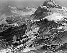
A small boat with two sails set climbs the steep side of a wave. In the background are the rocky tops of high cliffs and distant mountains
Depiction of the James Caird nearing South Georgia (from Shackleton's expedition account, South)

On 5 May the worst of the weather returned, and brought them close to disaster in the largest seas so far. Shackleton later wrote: "We felt our boat lifted and flung forward like a cork in breaking surf". The crew bailed frantically to keep afloat. Nevertheless, they were still moving towards their goal, and a dead reckoning calculation by Worsley on the next day, 6 May, suggested that they were now 115 nautical miles (213 km; 132 mi) from the western point of South Georgia. The strains of the past two weeks were by now taking their toll on the men. Shackleton observed that Vincent had collapsed and ceased to be an active member of the crew, McCarthy was "weak, but happy", McNish was weakening but still showing "grit and spirit".

Six men pulling a boat onto an icy shore, with a line of ice cliffs in the background
A depiction of the James Caird landing at South Georgia at the end of its voyage on 10 May 1916

On 7 May Worsley advised Shackleton that he could not be sure of their position within ten miles. To avoid the possibility of being swept past the island by the fierce south-westerly winds, Shackleton ordered a slight change of course so that the James Caird would reach land on the uninhabited south-west coast. They would then try to work the boat round to the whaling stations on the northern side of the island. "Things were bad for us in those days", wrote Shackleton. "The bright moments were those when we each received our one mug of hot milk during the long, bitter watches of the night". Late on the same day floating seaweed was spotted, and the next morning there were birds, including cormorants which were known never to venture far from land. Shortly after noon on 8 May came the first sighting of South Georgia.

As they approached the high cliffs of the coastline, heavy seas made immediate landing impossible. For more than 24 hours they were forced to stand clear, as the wind shifted to the north-west and quickly developed into "one of the worst hurricanes any of us had ever experienced". For much of this time they were in danger of being driven on to the rocky South Georgia shore, or of being wrecked on the equally menacing Annenkov Island, five miles from the coast. On 10 May, when the storm had eased slightly, Shackleton was concerned that the weaker members of his crew would not last another day, and decided that whatever the hazard they must attempt a landing. They headed for Cave Cove near the entrance to King Haakon Bay, and finally, after several attempts, made their landing there. Shackleton was later to describe the boat journey as "one of supreme strife"; historian Caroline Alexander comments: "They could hardly have known—or cared—that in the carefully weighted judgement of authorities yet to come, the voyage of the James Caird would be ranked as one of the greatest boat journeys ever accomplished".

South Georgia

Outline of a long, narrow irregular-shaped island with small islands around its coasts. The main island is labelled "South Georgia", and various place names are shown on its north coast including Stromness Husvik and Grytviken.
South Georgia. King Haakon Bay, where the James Caird landed, is the large indentation at the western (upper) end of the southerly side.
Elephant Isle party being rescued by the tug Yelcho, visible in the distance

As the party recuperated, Shackleton realised that the boat was not capable of making a further voyage to reach the whaling stations, and that Vincent and McNish were unfit to travel further. He decided to move the boat to a safer location within King Haakon Bay, from which point he, Worsley and Crean would cross the island on foot, aiming for the station at Stromness.

On 15 May the James Caird made a run of about 6 nautical miles (11 km; 6.9 mi) to a shingle beach near the head of the bay. Here the boat was beached and up-turned to provide a shelter. The location was christened "Peggotty Camp" (after Peggotty's boat-home in Charles Dickens's David Copperfield). Early on 18 May Shackleton, Worsley and Crean began what would be the first confirmed land crossing of the South Georgia interior. Since they had no map, they had to improvise a route across mountain ranges and glaciers. They travelled continuously for 36 hours, before reaching Stromness. Shackleton's men were, in Worsley's words, "a terrible trio of scarecrows", dark with exposure, wind, frostbite and accumulated blubber soot. Later that evening, 19 May, a motor-vessel (the Norwegian whale catcher Samson) was despatched to King Haakon Bay to pick up McCarthy, McNish and Vincent, and the James Caird. Worsley wrote that the Norwegian seamen at Stromness all "claimed the honour of helping to haul her up to the wharf", a gesture which he found "quite affecting".

The advent of the southern winter and adverse ice conditions meant that it was more than three months before Shackleton was able to achieve the relief of the men at Elephant Island. His first attempt was with the British ship Southern Sky. Then the government of Uruguay loaned him a ship. While searching on the Falkland Islands he found the ship Emma for his third attempt, but the ship's engine blew. Then, finally, with the aid of the steam-tug Yelcho commanded by Luis Pardo, the entire party was brought to safety, reaching Punta Arenas in Chile on 3 September 1916.

Aftermath

White-hulled small boat sitting on a base of stones behind a rail, within a museum. The name "James Caird" is visible. A stuffed penguin in a glass case stands nearby.
The James Caird, preserved at Dulwich College in south London

The James Caird was returned to England in 1919. In 1921, Shackleton went back to Antarctica, leading the Shackleton–Rowett Expedition. On 5 January 1922, he died suddenly of a heart attack, while the expedition's ship Quest was moored at South Georgia.

Later that year John Quiller Rowett, who had financed this last expedition and was a former school friend of Shackleton's from Dulwich College, South London, decided to present the James Caird to the college. It remained there until 1967, although its display building was severely damaged by bombs in 1944.

In 1967, thanks to a pupil at Dulwich College, Howard Hope, who was dismayed at the state of the boat, it was given to the care of the National Maritime Museum, and underwent restoration. It was then displayed by the museum until 1985, when it was returned to Dulwich College and placed in a new location in the North Cloister, on a bed of stones gathered from South Georgia and Aberystwyth. This site has become the James Caird's permanent home, although the boat is sometimes lent to major exhibitions and has taken part in the London Boat Show and in events at Greenwich, Portsmouth, and Falmouth. It has travelled overseas to be exhibited in Washington, D.C., New York, Sydney, Australia, Wellington (Te Papa) New Zealand and Bonn, Germany.

Howard Hope on a visit

The James Caird Society was established in 1994, to "preserve the memory, honour the remarkable feats of discovery in the Antarctic, and commend the outstanding qualities of leadership associated with the name of Sir Ernest Shackleton".

In 2000, German polar explorer Arved Fuchs built a detailed copy of Shackleton's boat—named James Caird II—for his replication of the voyage of Shackleton and his crew from Elephant Island to South Georgia. The James Caird II was among the first exhibitions when the International Maritime Museum in Hamburg was opened. A further replica, James Caird III, was built and purchased by the South Georgia Heritage Trust, and since 2008 has been on display at the South Georgia Museum at Grytviken.

Replica

In 2013, Australian explorer Tim Jarvis and five others successfully recreated Shackleton's crossing of the Southern Ocean in the Alexandra Shackleton, a replica of the James Caird. The construction of the replica James Caird was started in June 2008 and was finished in 2010, and was officially launched on 18 March 2012 in Dorset. Using the same materials, clothing, food, and chronometer, Jarvis and the team sailed their replica James Caird from Elephant Island to South Georgia, just as Shackleton did in 1916.

Dead reckoning

From Wikipedia, the free encyclopedia

The navigator plots their 9 a.m. position, indicated by the triangle, and, using their course and speed, estimates their own position at 9:30 and 10 a.m.

In navigation, dead reckoning is the process of calculating the current position of a moving object by using a previously determined position, or fix, and incorporating estimates of speed, heading (or direction or course), and elapsed time. The corresponding term in biology, to describe the processes by which animals update their estimates of position or heading, is path integration.

Advances in navigational aids that give accurate information on position, in particular satellite navigation using the Global Positioning System, have made simple dead reckoning by humans obsolete for most purposes. However, inertial navigation systems, which provide very accurate directional information, use dead reckoning and are very widely applied.

Etymology

Contrary to myth, the term "dead reckoning" was not originally used to abbreviate "deduced reckoning", nor is it a misspelling of the term "ded reckoning". The use of "ded" or "deduced reckoning" is not known to have appeared earlier than 1931, much later in history than "dead reckoning", which appeared as early as 1613 in the Oxford English Dictionary. The original intention of "dead" in the term is generally assumed to mean using a stationary object that is "dead in the water" as a basis for calculations. Additionally, at the time the first appearance of "dead reckoning", "ded" was considered a common spelling of "dead". This potentially led to later confusion of the origin of the term.

By analogy with their navigational use, the words dead reckoning are also used to mean the process of estimating the value of any variable quantity by using an earlier value and adding whatever changes have occurred in the meantime. Often, this usage implies that the changes are not known accurately. The earlier value and the changes may be measured or calculated quantities.

Errors

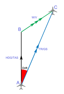
Drift is an error that can arise in dead reckoning when speed of a medium is not accounted for. A is the last known position (fix), B is the position calculated by dead reckoning, and C is the true position after the time interval. The vector from A to B is the expected path for plane based on the initial heading (HDG) and true airspeed (TAS). The vector from B to C is the wind velocity (W/V), and the third vector is the actual track (TR) and ground speed (GS). The drift angle is marked in red.

While dead reckoning can give the best available information on the present position with little math or analysis, it is subject to significant errors of approximation. For precise positional information, both speed and direction must be accurately known at all times during travel. Most notably, dead reckoning does not account for directional drift during travel through a fluid medium. These errors tend to compound themselves over greater distances, making dead reckoning a difficult method of navigation for longer journeys.

For example, if displacement is measured by the number of rotations of a wheel, any discrepancy between the actual and assumed traveled distance per rotation, due perhaps to slippage or surface irregularities, will be a source of error. As each estimate of position is relative to the previous one, errors are cumulative, or compounding, over time.

The accuracy of dead reckoning can be increased significantly by using other, more reliable methods to get a new fix part way through the journey. For example, if one was navigating on land in poor visibility, then dead reckoning could be used to get close enough to the known position of a landmark to be able to see it, before walking to the landmark itself—giving a precisely known starting point—and then setting off again.

Localization of mobile sensor nodes

Localizing a static sensor node is not a difficult task because attaching a Global Positioning System (GPS) device suffices the need of localization. But a mobile sensor node, which continuously changes its geographical location with time is difficult to localize. Mostly mobile sensor nodes within some particular domain for data collection can be used, i.e, sensor node attached to an animal within a grazing field or attached to a soldier on a battlefield. Within these scenarios a GPS device for each sensor node cannot be afforded. Some of the reasons for this include cost, size and battery drainage of constrained sensor nodes. To overcome this problem a limited number of reference nodes (with GPS) within a field is employed. These nodes continuously broadcast their locations and other nodes in proximity receive these locations and calculate their position using some mathematical technique like trilateration. For localization, at least three known reference locations are necessary to localize. Several localization algorithms based on Sequential Monte Carlo (SMC) method have been proposed in literature. Sometimes a node at some places receives only two known locations and hence it becomes impossible to localize. To overcome this problem, dead reckoning technique is used. With this technique a sensor node uses its previous calculated location for localization at later time intervals. For example, at time instant 1 if node A calculates its position as loca_1 with the help of three known reference locations; then at time instant 2 it uses loca_1 along with two other reference locations received from other two reference nodes. This not only localizes a node in less time but also localizes in positions where it is difficult to get three reference locations.

Animal navigation

In studies of animal navigation, dead reckoning is more commonly (though not exclusively) known as path integration. Animals use it to estimate their current location based on their movements from their last known location. Animals such as ants, rodents, and geese have been shown to track their locations continuously relative to a starting point and to return to it, an important skill for foragers with a fixed home.

Vehicular navigation

Marine

Dead reckoning navigation tools in coastal navigation

In marine navigation a "dead" reckoning plot generally does not take into account the effect of currents or wind. Aboard ship a dead reckoning plot is considered important in evaluating position information and planning the movement of the vessel.

Dead reckoning begins with a known position, or fix, which is then advanced, mathematically or directly on the chart, by means of recorded heading, speed, and time. Speed can be determined by many methods. Before modern instrumentation, it was determined aboard ship using a chip log. More modern methods include pit log referencing engine speed (e.g. in rpm) against a table of total displacement (for ships) or referencing one's indicated airspeed fed by the pressure from a pitot tube. This measurement is converted to an equivalent airspeed based upon known atmospheric conditions and measured errors in the indicated airspeed system. A naval vessel uses a device called a pit sword (rodmeter), which uses two sensors on a metal rod to measure the electromagnetic variance caused by the ship moving through water. This change is then converted to ship's speed. Distance is determined by multiplying the speed and the time. This initial position can then be adjusted resulting in an estimated position by taking into account the current (known as set and drift in marine navigation). If there is no positional information available, a new dead reckoning plot may start from an estimated position. In this case subsequent dead reckoning positions will have taken into account estimated set and drift.

Dead reckoning positions are calculated at predetermined intervals, and are maintained between fixes. The duration of the interval varies. Factors including one's speed made good and the nature of heading and other course changes, and the navigator's judgment determine when dead reckoning positions are calculated.

Before the 18th-century development of the marine chronometer by John Harrison and the lunar distance method, dead reckoning was the primary method of determining longitude available to mariners such as Christopher Columbus and John Cabot on their trans-Atlantic voyages. Tools such as the traverse board were developed to enable even illiterate crew members to collect the data needed for dead reckoning. Polynesian navigation, however, uses different wayfinding techniques.

Air

British P10 Magnetic Compass with dead reckoning navigation tools

On 14 June, 1919, John Alcock and Arthur Brown took off from Lester's Field in St. John's, Newfoundland in a Vickers Vimy. They navigated across the Atlantic Ocean by dead reckoning and landed in County Galway, Ireland at 8:40 a.m. on 15 June completing the first non-stop transatlantic flight.

On 21 May 1927 Charles Lindbergh landed in Paris, France after a successful non-stop flight from the United States in the single-engined Spirit of St. Louis. As the aircraft was equipped with very basic instruments, Lindbergh used dead reckoning to navigate.

Dead reckoning in the air is similar to dead reckoning on the sea, but slightly more complicated. The density of the air the aircraft moves through affects its performance as well as winds, weight, and power settings.

The basic formula for DR is Distance = Speed x Time. An aircraft flying at 250 knots airspeed for 2 hours has flown 500 nautical miles through the air. The wind triangle is used to calculate the effects of wind on heading and airspeed to obtain a magnetic heading to steer and the speed over the ground (groundspeed). Printed tables, formulae, or an E6B flight computer are used to calculate the effects of air density on aircraft rate of climb, rate of fuel burn, and airspeed.

A course line is drawn on the aeronautical chart along with estimated positions at fixed intervals (say every half hour). Visual observations of ground features are used to obtain fixes. By comparing the fix and the estimated position corrections are made to the aircraft's heading and groundspeed.

Dead reckoning is on the curriculum for VFR (visual flight rules – or basic level) pilots worldwide. It is taught regardless of whether the aircraft has navigation aids such as GPS, ADF and VOR and is an ICAO Requirement. Many flying training schools will prevent a student from using electronic aids until they have mastered dead reckoning.

Inertial navigation systems (INSes), which are nearly universal on more advanced aircraft, use dead reckoning internally. The INS provides reliable navigation capability under virtually any conditions, without the need for external navigation references, although it is still prone to slight errors.

Automotive

Dead reckoning is today implemented in some high-end automotive navigation systems in order to overcome the limitations of GPS/GNSS technology alone. Satellite microwave signals are unavailable in parking garages and tunnels, and often severely degraded in urban canyons and near trees due to blocked lines of sight to the satellites or multipath propagation. In a dead-reckoning navigation system, the car is equipped with sensors that know the wheel circumference and record wheel rotations and steering direction. These sensors are often already present in cars for other purposes (anti-lock braking system, electronic stability control) and can be read by the navigation system from the controller-area network bus. The navigation system then uses a Kalman filter to integrate the always-available sensor data with the accurate but occasionally unavailable position information from the satellite data into a combined position fix.

Autonomous navigation in robotics

Dead reckoning is utilized in some robotic applications. It is usually used to reduce the need for sensing technology, such as ultrasonic sensors, GPS, or placement of some linear and rotary encoders, in an autonomous robot, thus greatly reducing cost and complexity at the expense of performance and repeatability. The proper utilization of dead reckoning in this sense would be to supply a known percentage of electrical power or hydraulic pressure to the robot's drive motors over a given amount of time from a general starting point. Dead reckoning is not totally accurate, which can lead to errors in distance estimates ranging from a few millimeters (in CNC machining) to kilometers (in UAVs), based upon the duration of the run, the speed of the robot, the length of the run, and several other factors.

Pedestrian dead reckoning

With the increased sensor offering in smartphones, built-in accelerometers can be used as a pedometer and built-in magnetometer as a compass heading provider. Pedestrian dead reckoning (PDR) can be used to supplement other navigation methods in a similar way to automotive navigation, or to extend navigation into areas where other navigation systems are unavailable.

In a simple implementation, the user holds their phone in front of them and each step causes position to move forward a fixed distance in the direction measured by the compass. Accuracy is limited by the sensor precision, magnetic disturbances inside structures, and unknown variables such as carrying position and stride length. Another challenge is differentiating walking from running, and recognizing movements like bicycling, climbing stairs, or riding an elevator.

Before phone-based systems existed, many custom PDR systems existed. While a pedometer can only be used to measure linear distance traveled, PDR systems have an embedded magnetometer for heading measurement. Custom PDR systems can take many forms including special boots, belts, and watches, where the variability of carrying position has been minimized to better utilize magnetometer heading. True dead reckoning is fairly complicated, as it is not only important to minimize basic drift, but also to handle different carrying scenarios and movements, as well as hardware differences across phone models.

Directional dead reckoning

The south-pointing chariot was an ancient Chinese device consisting of a two-wheeled horse-drawn vehicle which carried a pointer that was intended always to aim to the south, no matter how the chariot turned. The chariot pre-dated the navigational use of the magnetic compass, and could not detect the direction that was south. Instead it used a kind of directional dead reckoning: at the start of a journey, the pointer was aimed southward by hand, using local knowledge or astronomical observations e.g. of the Pole Star. Then, as it traveled, a mechanism possibly containing differential gears used the different rotational speeds of the two wheels to turn the pointer relative to the body of the chariot by the angle of turns made (subject to available mechanical accuracy), keeping the pointer aiming in its original direction, to the south. Errors, as always with dead reckoning, would accumulate as distance traveled increased.

For networked games

Networked games and simulation tools routinely use dead reckoning to predict where an actor should be right now, using its last known kinematic state (position, velocity, acceleration, orientation, and angular velocity). This is primarily needed because it is impractical to send network updates at the rate that most games run, 60 Hz. The basic solution starts by projecting into the future using linear physics:

This formula is used to move the object until a new update is received over the network. At that point, the problem is that there are now two kinematic states: the currently estimated position and the just received, actual position. Resolving these two states in a believable way can be quite complex. One approach is to create a curve (e.g. cubic Bézier splines, centripetal Catmull–Rom splines, and Hermite curves) between the two states while still projecting into the future. Another technique is to use projective velocity blending, which is the blending of two projections (last known and current) where the current projection uses a blending between the last known and current velocity over a set time.

The first equation calculates a blended velocity given the client-side velocity at the time of the last server update and the last known server-side velocity . This essentially blends from the client-side velocity towards the server-side velocity for a smooth transition. Note that should go from zero (at the time of the server update) to one (at the time at which the next update should be arriving). A late server update is unproblematic as long as remains at one.

Next, two positions are calculated: firstly, the blended velocity and the last known server-side acceleration are used to calculate . This is a position which is projected from the client-side start position based on , the time which has passed since the last server update. Secondly, the same equation is used with the last known server-side parameters to calculate the position projected from the last known server-side position and velocity , resulting in .

Finally, the new position to display on the client is the result of interpolating from the projected position based on client information towards the projected position based on the last known server information . The resulting movement smoothly resolves the discrepancy between client-side and server-side information, even if this server-side information arrives infrequently or inconsistently. It is also free of oscillations which spline-based interpolation may suffer from.

Computer science

In computer science, dead-reckoning refers to navigating an array data structure using indexes. Since every array element has the same size, it is possible to directly access one array element by knowing any position in the array.

Given the following array:

A B C D E

knowing the memory address where the array starts, it is easy to compute the memory address of D:

Likewise, knowing D's memory address, it is easy to compute the memory address of B:

This property is particularly important for performance when used in conjunction with arrays of structures because data can be directly accessed, without going through a pointer dereference.

Representation of a Lie group

From Wikipedia, the free encyclopedia https://en.wikipedia.org/wiki/Representation_of_a_Lie_group...