Search This Blog

Friday, November 2, 2018

Demand response

From Wikipedia, the free encyclopedia

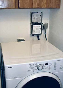
A clothes dryer using a demand response switch to reduce peak demand
 
Daily load diagram; Blue shows real load usage and green shows ideal load.

Demand response is a change in the power consumption of an electric utility customer to better match the demand for power with the supply. Until recently electric energy could not be easily stored, so utilities have traditionally matched demand and supply by throttling the production rate of their power plants, taking generating units on or off line, or importing power from other utilities. There are limits to what can be achieved on the supply side, because some generating units can take a long time to come up to full power, some units may be very expensive to operate, and demand can at times be greater than the capacity of all the available power plants put together. Demand response seeks to adjust the demand for power instead of adjusting the supply.

Utilities may signal demand requests to their customers in a variety of ways, including simple off-peak metering, in which power is cheaper at certain times of the day, and smart metering, in which explicit requests or changes in price can be communicated to customers.

The customer may adjust power demand by postponing some tasks that require large amounts of electric power, or may decide to pay a higher price for their electricity. Some customers may switch part of their consumption to alternate sources, such as on-site diesel generators.

In many respects, demand response can be put simply as a technology-enabled economic rationing system for electric power supply. In demand response, voluntary rationing is accomplished by price incentives—offering lower net unit pricing in exchange for reduced power consumption in peak periods. The direct implication is that users of electric power capacity not reducing usage (load) during peak periods will pay "surge" unit prices, whether directly, or factored into general rates.

Involuntary rationing, if employed, would be accomplished via rolling blackouts during peak load periods. Practically speaking, summer heat waves and winter deep freezes might be characterized by planned power outages for consumers and businesses if voluntary rationing via incentives fail to reduce load adequately to match total power supply.

Background

According to the Federal Energy Regulatory Commission, demand response (DR) is defined as: “Changes in electric usage by end-use customers from their normal consumption patterns in response to changes in the price of electricity over time, or to incentive payments designed to induce lower electricity use at times of high wholesale market prices or when system reliability is jeopardized.” DR includes all intentional modifications to consumption patterns of electricity to induce customers that are intended to alter the timing, level of instantaneous demand, or the total electricity consumption. It is expected that demand response programs will be designed to decrease electricity consumption or shift it from on-peak to off-peak periods depending on consumers’ preferences and lifestyles. Demand Response can be defined as "a wide range of actions which can be taken at the customer side of the electricity meter in response to particular conditions within the electricity system (such as peak period network congestion or high prices)". Demand response is a reduction in demand designed to reduce peak demand or avoid system emergencies. Hence, demand response can be a more cost-effective alternative than adding generation capabilities to meet the peak and or occasional demand spikes. The underlying objective of DR is to actively engage customers in modifying their consumption in response to pricing signals. The goal is to reflect supply expectations through consumer price signals or controls and enable dynamic changes in consumption relative to price.

In electricity grids, DR is similar to dynamic demand mechanisms to manage customer consumption of electricity in response to supply conditions, for example, having electricity customers reduce their consumption at critical times or in response to market prices. The difference is that demand response mechanisms respond to explicit requests to shut off, whereas dynamic demand devices passively shut off when stress in the grid is sensed. Demand response can involve actually curtailing power used or by starting on-site generation which may or may not be connected in parallel with the grid. This is a quite different concept from energy efficiency, which means using less power to perform the same tasks, on a continuous basis or whenever that task is performed. At the same time, demand response is a component of smart energy demand, which also includes energy efficiency, home and building energy management, distributed renewable resources, and electric vehicle charging.

Current demand response schemes are implemented with large and small commercial as well as residential customers, often through the use of dedicated control systems to shed loads in response to a request by a utility or market price conditions. Services (lights, machines, air conditioning) are reduced according to a preplanned load prioritization scheme during the critical time frames. An alternative to load shedding is on-site generation of electricity to supplement the power grid. Under conditions of tight electricity supply, demand response can significantly decrease the peak price and, in general, electricity price volatility.

Demand response is generally used to refer to mechanisms used to encourage consumers to reduce demand, thereby reducing the peak demand for electricity. Since electrical generation and transmission systems are generally sized to correspond to peak demand (plus margin for forecasting error and unforeseen events), lowering peak demand reduces overall plant and capital cost requirements. Depending on the configuration of generation capacity, however, demand response may also be used to increase demand (load) at times of high production and low demand. Some systems may thereby encourage energy storage to arbitrage between periods of low and high demand (or low and high prices).

There are three types of demand response - emergency demand response, economic demand response and ancillary services demand response. Emergency demand response is employed to avoid involuntary service interruptions during times of supply scarcity. Economic demand response is employed to allow electricity customers to curtail their consumption when the productivity or convenience of consuming that electricity is worth less to them than paying for the electricity. Ancillary services demand response consists of a number of specialty services that are needed to ensure the secure operation of the transmission grid and which have traditionally been provided by generators.

Smart grid application

Smart grid applications improve the ability of electricity producers and consumers to communicate with one another and make decisions about how and when to produce and consume electrical power. This emerging technology will allow customers to shift from an event-based demand response where the utility requests the shedding of load, towards a more 24/7-based demand response where the customer sees incentives for controlling load all the time. Although this back-and-forth dialogue increases the opportunities for demand response, customers are still largely influenced by economic incentives and are reluctant to relinquish total control of their assets to utility companies.

One advantage of a smart grid application is time-based pricing. Customers who traditionally pay a fixed rate for consumed energy (kWh) and requested peak load can set their threshold and adjust their usage to take advantage of fluctuating prices. This may require the use of an energy management system to control appliances and equipment and can involve economies of scale. Another advantage, mainly for large customers with generation, is being able to closely monitor, shift, and balance load in a way that allows the customer to save peak load and not only save on kWh and kW/month but be able to trade what they have saved in an energy market. Again this involves sophisticated energy management systems, incentives, and a viable trading market.

Smart grid applications increase the opportunities for demand response by providing real time data to producers and consumers, but the economic and environmental incentives remain the driving force behind the practice.

One of the most important means of demand response in the future smart grids is electric vehicles. Aggregation of this new source of energy, which is also a new source of uncertainty in the electrical systems, is critical to preserving the stability and quality of smart grids, consequently, the electric vehicle parking lots can be considered a demand response aggregation entity.

Electricity pricing

Explanation of demand response effects on a quantity (Q) - 
price (P) graph. Under inelastic demand (D1) extremely high
price (P1) may result on a strained electricity market. If demand response measures are employed the demand becomes more
elastic (D2). A much lower price will result in the market (P2).

It is estimated that a 5% lowering of demand would result in a
50% price reduction during the peak hours of the California
electricity crisis in 2000/2001. The market also becomes more resilient to intentional withdrawal of offers from the supply side.

In most electric power systems, some or all consumers pay a fixed price per unit of electricity independent of the cost of production at the time of consumption. The consumer price may be established by the government or a regulator, and typically represents an average cost per unit of production over a given timeframe (for example, a year). Consumption therefore is not sensitive to the cost of production in the short term (e.g. on an hourly basis). In economic terms, consumers' usage of electricity is inelastic in short time frames since the consumers do not face the actual price of production; if consumers were to face the short run costs of production they would be more inclined to change their use of electricity in reaction to those price signals. A pure economist might extrapolate the concept to hypothesize that consumers served under these fixed-rate tariffs are endowed with theoretical "call options" on electricity, though in reality, like any other business, the customer is simply buying what is on offer at the agreed price. A customer in a department store buying a $10 item at 9.00 am might notice 10 sales staff on the floor but only one occupied serving him or her, while at 3.00 pm the customer could buy the same $10 article and notice all 10 sales staff occupied. In a similar manner, the department store cost of sales at 9.00 am might therefore be 5-10 times that of its cost of sales at 3.00 pm, but it would be far-fetched to claim that the customer, by not paying significantly more for the article at 9.00 am than at 3.00 pm, had a 'call option' on the $10 article.

In virtually all power systems electricity is produced by generators that are dispatched in merit order, i.e., generators with the lowest marginal cost (lowest variable cost of production) are used first, followed by the next cheapest, etc., until the instantaneous electricity demand is satisfied. In most power systems the wholesale price of electricity will be equal to the marginal cost of the highest cost generator that is injecting energy, which will vary with the level of demand. Thus the variation in pricing can be significant: for example, in Ontario between August and September 2006, wholesale prices (in Canadian Dollars) paid to producers ranged from a peak of $318 per MW·h to a minimum of - (negative) $3.10 per MW·h. It is not unusual for the price to vary by a factor of two to five due to the daily demand cycle. A negative price indicates that producers were being charged to provide electricity to the grid (and consumers paying real-time pricing may have actually received a rebate for consuming electricity during this period). This generally occurs at night when demand falls to a level where all generators are operating at their minimum output levels and some of them must be shut down. The negative price is the inducement to bring about these shutdowns in a least-cost manner.

Two Carnegie Mellon studies in 2006 looked at the importance of demand response for the electricity industry in general terms and with specific application of real-time pricing for consumers for the PJM Interconnection Regional Transmission authority. The latter study found that even small shifts in peak demand would have a large effect on savings to consumers and avoided costs for additional peak capacity: a 1% shift in peak demand would result in savings of 3.9%, billions of dollars at the system level. An approximately 10% reduction in peak demand (achievable depending on the elasticity of demand) would result in systems savings of between $8 to $28 billion.

In a discussion paper, Ahmad Faruqui, a principal with the Brattle Group, estimates that a 5 percent reduction in US peak electricity demand could produce approximately $35 billion in cost savings over a 20-year period, exclusive of the cost of the metering and communications needed to implement the dynamic pricing needed to achieve these reductions. While the net benefits would be significantly less than the claimed $35 billion, they would still be quite substantial. In Ontario, Canada, the Independent Electricity System Operator has noted that in 2006, peak demand exceeded 25,000 megawatts during only 32 system hours (less than 0.4% of the time), while maximum demand during the year was just over 27,000 megawatts. The ability to "shave" peak demand based on reliable commitments would therefore allow the province to reduce built capacity by approximately 2,000 megawatts.

Electricity grids and peak demand response

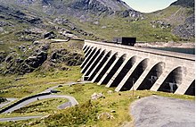
The upper reservoir (Llyn Stwlan) and dam of the Ffestiniog Pumped Storage Scheme in north Wales

In an electricity grid, electricity consumption and production must balance at all times; any significant imbalance could cause grid instability or severe voltage fluctuations, and cause failures within the grid. Total generation capacity is therefore sized to correspond to total peak demand with some margin of error and allowance for contingencies (such as plants being off-line during peak demand periods). Operators will generally plan to use the least expensive generating capacity (in terms of marginal cost) at any given period, and use additional capacity from more expensive plants as demand increases. Demand response in most cases is targeted at reducing peak demand to reduce the risk of potential disturbances, avoid additional capital cost requirements for additional plants, and avoid use of more expensive and/or less efficient operating plants. Consumers of electricity will also pay higher prices if generation capacity is used from a higher-cost source of power generation.

Demand response may also be used to increase demand during periods of high supply and/or low demand. Some types of generating plant must be run at close to full capacity (such as nuclear), while other types may produce at negligible marginal cost (such as wind and solar). Since there is usually limited capacity to store energy, demand response may attempt to increase load during these periods to maintain grid stability. For example, in the province of Ontario in September 2006, there was a short period of time when electricity prices were negative for certain users. Energy storage such as pumped-storage hydroelectricity is a way to increase load during periods of low demand for use during later periods. Use of demand response to increase load is less common, but may be necessary or efficient in systems where there are large amounts of generating capacity that cannot be easily cycled down.

Some grids may use pricing mechanisms that are not real-time, but easier to implement (users pay higher prices during the day and lower prices at night, for example) to provide some of the benefits of the demand response mechanism with less demanding technological requirements. In the UK, Economy 7 and similar schemes that attempt to shift demand associated with electric heating to overnight off-peak periods have been in operation since the 1970s. More recently, in 2006 Ontario began implementing a "smart meter" program that implements "time-of-use" (TOU) pricing, which tiers pricing according to on-peak, mid-peak and off-peak schedules. During the winter, on-peak is defined as morning and early evening, mid-peak as midday to late afternoon, and off-peak as nighttime; during the summer, the on-peak and mid-peak periods are reversed, reflecting air conditioning as the driver of summer demand. As of May 1, 2015, most Ontario electrical utilities have completed converting all customers to "smart meter" time-of-use billing with on-peak rates about 200% and mid-peak rates about 150% of the off-peak rate per kWh.

Australia has national standards for Demand Response (AS/NZS 4755 series), which has been implemented nation wide by electricity distributors for several decades, e.g. controlling storage water heaters, air conditioners and pool pumps. In 2016, how to manage electrical energy storage (e.g. batteries) has been added into the series of standards.

Load shedding

Electrical generation and transmission systems may not always meet peak demand requirements— the greatest amount of electricity required by all utility customers within a given region. In these situations, overall demand must be lowered, either by turning off service to some devices or cutting back the supply voltage (brownouts), in order to prevent uncontrolled service disruptions such as power outages (widespread blackouts) or equipment damage. Utilities may impose load shedding on service areas via rolling blackouts or by agreements with specific high-use industrial consumers to turn off equipment at times of system-wide peak demand.

Incentives to shed loads

Energy consumers need some incentive to respond to such a request from a demand response provider (see list of providers below). Demand response incentives can be formal or informal. For example, the utility might create a tariff-based incentive by passing along short-term increases in the price of electricity, or they might impose mandatory cutbacks during a heat wave for selected high-volume users, who are compensated for their participation. Other users may receive a rebate or other incentive based on firm commitments to reduce power during periods of high demand, sometimes referred to as negawatts.

Commercial and industrial power users might impose load shedding on themselves, without a request from the utility. Some businesses generate their own power and wish to stay within their energy production capacity to avoid buying power from the grid. Some utilities have commercial tariff structures that set a customer's power costs for the month based on the customer's moment of highest use, or peak demand. This encourages users to flatten their demand for energy, known as energy demand management, which sometimes requires cutting back services temporarily.

Smart metering has been implemented in some jurisdictions to provide real-time pricing for all types of users, as opposed to fixed-rate pricing throughout the demand period. In this application, users have a direct incentive to reduce their use at high-demand, high-price periods. Many users may not be able to effectively reduce their demand at various times, or the peak prices may be lower than the level required to induce a change in demand during short time periods (users have low price sensitivity, or elasticity of demand is low). Automated control systems exist, which, although effective, may be too expensive to be feasible for some applications.

Application for intermittent renewable distributed energy resources

The modern power grid is making a transition from the traditional vertically integrated utility structures to distributed systems as we begin to integrate higher penetrations of renewable energy generation. These sources of energy are often diffusely distributed and intermittent by nature. These features introduce problems in grid stability and efficiency which lead to limitations on the amount of these resources which can be effectively added to the grid. In a traditional vertically integrated grid, energy is provided by utility generators which are able to respond to changes in demand. Generation output by renewable resources is governed by environmental conditions and is generally not able to respond to changes in demand. Responsive control over non-critical loads which are connected to the grid has been shown to be an effective strategy which is able to mitigate harmful fluctuations introduced by these renewable resources. In this way instead of letting the generation respond to changes in demand, we have the demand respond to changes in generation. This is the basis of demand response. In order to implement demand response systems, we must be able to coordinate large numbers of distributed resources through sensors, actuators, and communications protocols. To be effective, the devices need to be economical, robust, and yet still effective at managing their tasks of control. In addition, a strong control mechanism must be created which is able to coordinate over large networks of devices to manage and optimize these distributed systems both from an economic standpoint and a security standpoint in grid stabilization.

In addition, the increased presence of variable renewable generation drives a greater need for authorities to procure more ancillary services (AS) for grid balance. One of these services is contingency reserve (CR), which is used to regulate the grid frequency in contingencies. Many independent system operators (ISO) are structuring the rules of AS markets such that demand response (DR) can participate alongside traditional supply-side resources. The available capacity of the generators can be used more efficiently for power production which they were designed for and not CR, thereby cutting costs and reducing pollution. As the ratio of inverter-based generation compared to conventional generation increases, the mechanical inertia used to stabilize frequency decreases. When coupled with the sensitivity of inverter-based generation to transient frequencies, the provision of ancillary services from other sources than generators becomes increasingly important.

Technologies for demand reduction

Technologies are available, and more are under development, to automate the process of demand response. Such technologies detect the need for load shedding, communicate the demand to participating users, automate load shedding, and verify compliance with demand-response programs. GridWise and EnergyWeb are two major federal initiatives in the United States to develop these technologies. Universities and private industry are also doing research and development in this arena. Scalable and comprehensive software solutions for DR enable business and industry growth.
Some utilities are considering and testing automated systems connected to industrial, commercial and residential users that can reduce consumption at times of peak demand, essentially delaying draw marginally. Although the amount of demand delayed may be small, the implications for the grid (including financial) may be substantial, since system stability planning often involves building capacity for extreme peak demand events, plus a margin of safety in reserve. Such events may only occur a few times per year.

The process may involve turning down or off certain appliances or sinks (and, when demand is unexpectedly low, potentially increasing usage). For example, heating may be turned down or air conditioning or refrigeration may be turned up (turning up to a higher temperature uses less electricity), delaying slightly the draw until a peak in usage has passed. In the city of Toronto, certain residential users can participate in a program (Peaksaver AC) whereby the system operator can automatically control hot water heaters or air conditioning during peak demand; the grid benefits by delaying peak demand (allowing peaking plants time to cycle up or avoiding peak events), and the participant benefits by delaying consumption until after peak demand periods, when pricing should be lower. Although this is an experimental program, at scale these solutions have the potential to reduce peak demand considerably. The success of such programs depends on the development of appropriate technology, a suitable pricing system for electricity, and the cost of the underlying technology. Bonneville Power experimented with direct-control technologies in Washington and Oregon residences, and found that the avoided transmission investment would justify the cost of the technology.

Other methods to implementing demand response approach the issue of subtly reducing duty cycles rather than implementing thermostat setbacks. These can be implemented using customized building automation systems programming, or through swarm-logic methods coordinating multiple loads in a facility (e.g. Encycle's EnviroGrid controllers).

Similar approach can be implemented for managing air conditioning peak demand in summer peak regions. Pre-cooling or maintaining slightly higher thermostat setting can help with the peak demand reduction.

In 2008 it was announced that electric refrigerators will be sold in the UK sensing dynamic demand which will delay or advance the cooling cycle based on monitoring grid frequency  but they are not readily available as of 2018.

Industrial customers

Industrial customers are also providing demand response. Compared with commercial and residential loads, industrial loads have the following advantages: the magnitude of power consumption by an industrial manufacturing plant and the change in power it can provide are generally very large; besides, the industrial plants usually already have the infrastructures for control, communication and market participation, which enables the provision of demand response; moreover, some industrial plants such as the aluminum smelter are able to offer fast and accurate adjustments in their power consumption. For example, Alcoa's Warrick Operation is participating in MISO as a qualified demand response resource, and the Trimet Aluminium uses its smelter as a short-term mega-battery. The selection of suitable industries for demand response provision is typically based on an assessment of the so-called value of lost load.

Short-term inconvenience for long-term benefits

Shedding loads during peak demand is important because it reduces the need for new power plants. To respond to high peak demand, utilities build very capital-intensive power plants and lines. Peak demand happens just a few times a year, so those assets run at a mere fraction of their capacity. Electric users pay for this idle capacity through the prices they pay for electricity. According to the Demand Response Smart Grid Coalition, 10%–20% of electricity costs in the United States are due to peak demand during only 100 hours of the year. DR is a way for utilities to reduce the need for large capital expenditures, and thus keep rates lower overall; however, there is an economic limit to such reductions because consumers lose the productive or convenience value of the electricity not consumed. Thus, it is misleading to only look at the cost savings that demand response can produce without also considering what the consumer gives up in the process.

Importance for the operation of electricity markets

It is estimated that a 5% lowering of demand would have resulted in a 50% price reduction during the peak hours of the California electricity crisis in 2000–2001. With consumers facing peak pricing and reducing their demand, the market should become more resilient to intentional withdrawal of offers from the supply side.

Residential and commercial electricity use often vary drastically during the day, and demand response attempts to reduce the variability based on pricing signals. There are three underlying tenets to these programs:
  1. Unused electrical production facilities represent a less efficient use of capital (little revenue is earned when not operating).
  2. Electric systems and grids typically scale total potential production to meet projected peak demand (with sufficient spare capacity to deal with unanticipated events).
  3. By "smoothing" demand to reduce peaks, less investment in operational reserve will be required, and existing facilities will operate more frequently.
In addition, significant peaks may only occur rarely, such as two or three times per year, requiring significant capital investments to meet infrequent events.

US Energy Policy Act regarding demand response

The United States Energy Policy Act of 2005 has mandated the Secretary of Energy to submit to the US Congress "a report that identifies and quantifies the national benefits of demand response and makes a recommendation on achieving specific levels of such benefits by January 1, 2007." Such a report was published in February 2006.

The report estimates that in 2004 potential demand response capability equaled about 20,500 megawatts (MW), 3% of total U.S. peak demand, while actual delivered peak demand reduction was about 9,000 MW (1.3% of peak), leaving ample margin for improvement. It is further estimated that load management capability has fallen by 32% since 1996. Factors affecting this trend include fewer utilities offering load management services, declining enrollment in existing programs, the changing role and responsibility of utilities, and changing supply/demand balance.

To encourage the use and implementation of demand response in the United States, the Federal Energy Regulatory Commission (FERC) issued Order No. 745 in March 2011, which requires a certain level of compensation for providers of economic demand response that participate in wholesale power markets. The order is highly controversial and has been opposed by a number of energy economists, including Professor William W. Hogan at Harvard University's Kennedy School. Professor Hogan asserts that the order overcompensates providers of demand response, thereby encouraging the curtailment of electricity whose economic value exceeds the cost of producing it. Professor Hogan further asserts that Order No. 745 is anticompetitive and amounts to “…an application of regulatory authority to enforce a buyer’s cartel.” Several affected parties, including the State of California, have filed suit in federal court challenging the legality of Order 745. A debate regarding the economic efficiency and fairness of Order 745 appeared in a series of articles published in The Electricity Journal.

On May 23, 2014, the D.C. Circuit Court of Appeals vacated Order 745 in its entirety. On May 4, 2015, the United States Supreme Court agreed to review the DC Circuit's ruling, addressing two questions:
  1. Whether the Federal Energy Regulatory Commission reasonably concluded that it has authority under the Federal Power Act, 16 U. S. C. 791a et seq., to regulate the rules used by operators of wholesale electricity markets to pay for reductions in electricity consumption and to recoup those payments through adjustments to wholesale rates.
  2. Whether the Court of Appeals erred in holding that the rule issued by the Federal Energy Regulatory Commission is arbitrary and capricious.[50]
On January 25, 2016, the United States Supreme Court in a 6-2 decision in FERC v. Electric Power Supply Ass'n concluded that the Federal Energy Regulatory Commission acted within its authority to ensure "just and reasonable" rates in the wholesale energy market.

Demand reduction and the use of diesel generators in the UK National Grid

As of December 2009 UK National Grid had 2369 MW contracted to provide demand response, known as STOR, the demand side provides 839 MW (35%) from 89 sites. Of this 839 MW approximately 750 MW is back-up generation with the remaining being load reduction. A paper based on extensive half-hourly demand profiles and observed electricity demand shifting for different commercial and industrial buildings in the UK shows that only a small minority engaged in load shifting and demand turn-down, while the majority of demand response is provided by stand-by generators.

Electric power system

From Wikipedia, the free encyclopedia

A steam turbine used to provide electric power

An electric power system is a network of electrical components deployed to supply, transfer, and use electric power. An example of an electric power system is the grid that provides power to an extended area. An electrical grid power system can be broadly divided into the generators that supply the power, the transmission system that carries the power from the generating centres to the load centres, and the distribution system that feeds the power to nearby homes and industries. Smaller power systems are also found in industry, hospitals, commercial buildings and homes. The majority of these systems rely upon three-phase AC power—the standard for large-scale power transmission and distribution across the modern world. Specialised power systems that do not always rely upon three-phase AC power are found in aircraft, electric rail systems, ocean liners and automobiles.

History

A sketch of the Pearl Street Station

In 1881, two electricians built the world's first power system at Godalming in England. It was powered by two waterwheels and produced an alternating current that in turn supplied seven Siemens arc lamps at 250 volts and 34 incandescent lamps at 40 volts. However, supply to the lamps was intermittent and in 1882 Thomas Edison and his company, The Edison Electric Light Company, developed the first steam-powered electric power station on Pearl Street in New York City. The Pearl Street Station initially powered around 3,000 lamps for 59 customers. The power station generated direct current and operated at a single voltage. Direct current power could not be transformed easily or efficiently to the higher voltages necessary to minimise power loss during long-distance transmission, so the maximum economic distance between the generators and load was limited to around half a mile (800 m).

That same year in London, Lucien Gaulard and John Dixon Gibbs demonstrated the "secondary generator", namely the first transformer suitable for use in a real power system. The practical value of Gaulard and Gibbs' transformer was demonstrated in 1884 at Turin where the transformer was used to light up forty kilometres (25 miles) of railway from a single alternating current generator. Despite the success of the system, the pair made some fundamental mistakes. Perhaps the most serious was connecting the primaries of the transformers in series so that active lamps would affect the brightness of other lamps further down the line.

In 1885, Ottó Titusz Bláthy (1860–1939) of Ganz & Co.(Budapest) perfected the secondary generator of Gaulard and Gibbs, providing it with a closed iron core, and thus obtained the first true power transformer, which he dubbed with its present name. The same year, Bláthy and two other engineers of the company set up the ZBD system (from their initials) by implementing the parallel AC distribution proposed by British scientist R. Kennedy in 1883, in which several power transformers have their primary windings fed in parallel from a high-voltage distribution line. The system was presented at the 1885 National General Exhibition of Budapest.

In 1885 George Westinghouse, an American entrepreneur, obtained the patent rights to the Gaulard-Gibbs transformer and imported a number of them along with a Siemens generator, and set his engineers to experimenting with them in hopes of improving them for use in a commercial power system. In 1886, one of Westinghouse's engineers, William Stanley, also recognised the problem with connecting transformers in series as opposed to parallel and also realised that making the iron core of a transformer a fully enclosed loop would improve the voltage regulation of the secondary winding. Using this knowledge he built the first practical transformer-based alternating-current power system at Great Barrington, Massachusetts in 1886. Westinghouse would begin installing multi-voltage AC transformer systems in competition with the Edison company later that year. In 1888 Westinghouse also licensed Nikola Tesla's US patents for a polyphase AC induction motor and transformer designs and hired Tesla for one year to be a consultant at the Westinghouse Electric & Manufacturing Company's Pittsburgh labs.

By 1888, the electric power industry was flourishing, and power companies had built thousands of power systems (both direct and alternating current) in the United States and Europe. These networks were effectively dedicated to providing electric lighting. During this time the rivalry between Thomas Edison and George Westinghouse's companies had grown into a propaganda campaign over which form of transmission (direct or alternating current) was superior, a series of events known as the "War of Currents". In 1891, Westinghouse installed the first major power system that was designed to drive a 100 horsepower (75 kW) synchronous electric motor, not just provide electric lighting, at Telluride, Colorado. On the other side of the Atlantic, Mikhail Dolivo-Dobrovolsky of AEG and Charles Eugene Lancelot Brown of Maschinenfabrik Oerlikon, built the very first long-distance (175 km, a distance never tried before) high-voltage (15 kV, then a record) three-phase transmission line from Lauffen am Neckar to Frankfurt am Main for the Electrical Engineering Exhibition in Frankfurt, where power was used light lamps and move a water pump. In the US the AC/DC competition came to an end when Edison General Electric was taken over by their chief AC rival, the Thomson-Houston Electric Company, forming General Electric. In 1895, after a protracted decision-making process, alternating current was chosen as the transmission standard with Westinghouse building the Adams No. 1 generating station at Niagara Falls and General Electric building the three-phase alternating current power system to supply Buffalo at 11 kV.

Developments in power systems continued beyond the nineteenth century. In 1936 the first experimental high voltage direct current (HVDC) line using mercury arc valves was built between Schenectady and Mechanicville, New York. HVDC had previously been achieved by series-connected direct current generators and motors (the Thury system) although this suffered from serious reliability issues. The first solid-state metal diode suitable for general power uses was developed by Ernst Presser at TeKaDe, Germany, in 1928. It consisted of a layer of selenium applied on an aluminum plate. In 1957, a General Electric research group developed a solid-state p-n-p-n switch device that was successfully marketed in early 1958, starting a revolution in power electronics. In 1957, also Siemens demonstrated a solid-state rectifier, but it was not until the early 1970s that solid-state devices became the standard in HVDC, when GE emerged as one of the top suppliers of thyristor-based HVDC. In 1979, a European consortium including Siemens, Brown Boveri & Cie and AEG realized the record HVDC link from Cabora Bassa (Mozambique) to Johannesburg (South Africa), extending more than 1,420 km and rated 1.9 GW at ±533 kV, that resorted to top performing 3.2-kV thyristors, developed by AEG under GE’s license, In recent times, many important developments have come from extending innovations in the information and communications technology (ICT) field to the power engineering field. For example, the development of computers meant load flow studies could be run more efficiently allowing for much better planning of power systems. Advances in information technology and telecommunication also allowed for remote control of a power system's switchgear and generators.

Basics of electric power

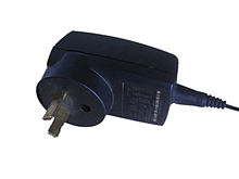
An external AC to DC power adapter used for household appliances

Electric power is the product of two quantities: current and voltage. These two quantities can vary with respect to time (AC power) or can be kept at constant levels (DC power).

Most refrigerators, air conditioners, pumps and industrial machinery use AC power whereas most computers and digital equipment use DC power (the digital devices you plug into the mains typically have an internal or external power adapter to convert from AC to DC power). AC power has the advantage of being easy to transform between voltages and is able to be generated and utilised by brushless machinery. DC power remains the only practical choice in digital systems and can be more economical to transmit over long distances at very high voltages (see HVDC).

The ability to easily transform the voltage of AC power is important for two reasons: Firstly, power can be transmitted over long distances with less loss at higher voltages. So in power systems where generation is distant from the load, it is desirable to step-up (increase) the voltage of power at the generation point and then step-down (decrease) the voltage near the load. Secondly, it is often more economical to install turbines that produce higher voltages than would be used by most appliances, so the ability to easily transform voltages means this mismatch between voltages can be easily managed.

Solid state devices, which are products of the semiconductor revolution, make it possible to transform DC power to different voltages, build brushless DC machines and convert between AC and DC power. Nevertheless, devices utilising solid state technology are often more expensive than their traditional counterparts, so AC power remains in widespread use.

Balancing the grid

One of the main difficulties in power systems is that the amount of active power consumed plus losses should always equal the active power produced. If more power is produced than consumed the frequency wil rise and vice versa. Even small deviations from the nominal frequency value will damage synchronous machines and other appliances. Making sure the frequency is constant is usually the task of a transmission system operator. In some countries (for example in the European Union) this is achieved through a balancing market using ancillary services.

Components of power systems

Supplies

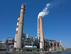
The majority of the world's power still comes from coal-fired power stations like this

All power systems have one or more sources of power. For some power systems, the source of power is external to the system but for others, it is part of the system itself—it is these internal power sources that are discussed in the remainder of this section. Direct current power can be supplied by batteries, fuel cells or photovoltaic cells. Alternating current power is typically supplied by a rotor that spins in a magnetic field in a device known as a turbo generator. There have been a wide range of techniques used to spin a turbine's rotor, from steam heated using fossil fuel (including coal, gas and oil) or nuclear energy, falling water (hydroelectric power) and wind (wind power).

The speed at which the rotor spins in combination with the number of generator poles determines the frequency of the alternating current produced by the generator. All generators on a single synchronous system, for example, the national grid, rotate at sub-multiples of the same speed and so generate electric current at the same frequency. If the load on the system increases, the generators will require more torque to spin at that speed and, in a typical power station, more steam must be supplied to the turbines driving them. Thus the steam used and the fuel expended are directly dependent on the quantity of electrical energy supplied. An exception exists for generators incorporating power electronics such as gearless wind turbines or linked to a grid through an asynchronous tie such as a HVDC link — these can operate at frequencies independent of the power system frequency.

Depending on how the poles are fed, alternating current generators can produce a variable number of phases of power. A higher number of phases leads to more efficient power system operation but also increases the infrastructure requirements of the system.

Electricity grid systems connect multiple generators and loads operating at the same frequency and number of phases, the commonest being three-phase at 50 or 60 Hz. However, there are other considerations. These range from the obvious: How much power should the generator be able to supply? What is an acceptable length of time for starting the generator (some generators can take hours to start)? Is the availability of the power source acceptable (some renewables are only available when the sun is shining or the wind is blowing)? To the more technical: How should the generator start (some turbines act like a motor to bring themselves up to speed in which case they need an appropriate starting circuit)? What is the mechanical speed of operation for the turbine and consequently what are the number of poles required? What type of generator is suitable (synchronous or asynchronous) and what type of rotor (squirrel-cage rotor, wound rotor, salient pole rotor or cylindrical rotor)?

Loads

A toaster is a great example of a single-phase load that might appear in a residence. Toasters typically draw 2 to 10 amps at 110 to 260 volts consuming around 600 to 1200 watts of power.

Power systems deliver energy to loads that perform a function. These loads range from household appliances to industrial machinery. Most loads expect a certain voltage and, for alternating current devices, a certain frequency and number of phases. The appliances found in your home, for example, will typically be single-phase operating at 50 or 60 Hz with a voltage between 110 and 260 volts (depending on national standards). An exception exists for centralized air conditioning systems as these are now typically three-phase because this allows them to operate more efficiently. All devices in your house will also have a wattage, this specifies the amount of power the device consumes. At any one time, the net amount of power consumed by the loads on a power system must equal the net amount of power produced by the supplies less the power lost in transmission.

Making sure that the voltage, frequency and amount of power supplied to the loads is in line with expectations is one of the great challenges of power system engineering. However it is not the only challenge, in addition to the power used by a load to do useful work (termed real power) many alternating current devices also use an additional amount of power because they cause the alternating voltage and alternating current to become slightly out-of-sync (termed reactive power). The reactive power like the real power must balance (that is the reactive power produced on a system must equal the reactive power consumed) and can be supplied from the generators, however it is often more economical to supply such power from capacitors (see "Capacitors and reactors" below for more details).

A final consideration with loads is to do with power quality. In addition to sustained overvoltages and undervoltages (voltage regulation issues) as well as sustained deviations from the system frequency (frequency regulation issues), power system loads can be adversely affected by a range of temporal issues. These include voltage sags, dips and swells, transient overvoltages, flicker, high-frequency noise, phase imbalance and poor power factor. Power quality issues occur when the power supply to a load deviates from the ideal: For an AC supply, the ideal is the current and voltage in-sync fluctuating as a perfect sine wave at a prescribed frequency with the voltage at a prescribed amplitude. For DC supply, the ideal is the voltage not varying from a prescribed level. Power quality issues can be especially important when it comes to specialist industrial machinery or hospital equipment.

Conductors

Conductors carry power from the generators to the load. In a grid, conductors may be classified as belonging to the transmission system, which carries large amounts of power at high voltages (typically more than 69 kV) from the generating centres to the load centres, or the distribution system, which feeds smaller amounts of power at lower voltages (typically less than 69 kV) from the load centres to nearby homes and industry.

Choice of conductors is based on considerations such as cost, transmission losses and other desirable characteristics of the metal like tensile strength. Copper, with lower resistivity than Aluminum, was the conductor of choice for most power systems. However, Aluminum has a lower cost for the same current carrying capacity and is the primary metal used for transmission line conductors. Overhead line conductors may be reinforced with steel or aluminium alloys.

Conductors in exterior power systems may be placed overhead or underground. Overhead conductors are usually air insulated and supported on porcelain, glass or polymer insulators. Cables used for underground transmission or building wiring are insulated with cross-linked polyethylene or other flexible insulation. Large conductors are stranded for ease of handling; small conductors used for building wiring are often solid, especially in light commercial or residential construction.

Conductors are typically rated for the maximum current that they can carry at a given temperature rise over ambient conditions. As current flow increases through a conductor it heats up. For insulated conductors, the rating is determined by the insulation. For overhead conductors, the rating is determined by the point at which the sag of the conductors would become unacceptable.

Capacitors and reactors

The majority of the load in a typical AC power system is inductive; the current lags behind the voltage. Since the voltage and current are out-of-phase, this leads to the emergence of an "imaginary" form of power known as reactive power. Reactive power does no measurable work but is transmitted back and forth between the reactive power source and load every cycle. This reactive power can be provided by the generators themselves, through the adjustment of generator excitation, but it is often cheaper to provide it through capacitors, hence capacitors are often placed near inductive loads to reduce current demand on the power system (i.e., increase the power factor), which may never exceed 1.0, and which represents a purely resistive load. Power factor correction may be applied at a central substation, through the use of so-called "synchronous condensers" (synchronous machines which act as condensers which are variable in VAR value, through the adjustment of machine excitation) or adjacent to large loads, through the use of so-called "static condensers" (condensers which are fixed in VAR value).

Reactors consume reactive power and are used to regulate voltage on long transmission lines. In light load conditions, where the loading on transmission lines is well below the surge impedance loading, the efficiency of the power system may actually be improved by switching in reactors. Reactors installed in series in a power system also limit rushes of current flow, small reactors are therefore almost always installed in series with capacitors to limit the current rush associated with switching in a capacitor. Series reactors can also be used to limit fault currents.

Capacitors and reactors are switched by circuit breakers, which results in moderately large steps in reactive power. A solution comes in the form of static VAR compensators and static synchronous compensators. Briefly, static VAR compensators work by switching in capacitors using thyristors as opposed to circuit breakers allowing capacitors to be switched-in and switched-out within a single cycle. This provides a far more refined response than circuit breaker switched capacitors. Static synchronous compensators take a step further by achieving reactive power adjustments using only power electronics.

Power electronics

Power electronics are semiconductor based devices that are able to switch quantities of power ranging from a few hundred watts to several hundred megawatts. Despite their relatively simple function, their speed of operation (typically in the order of nanoseconds) means they are capable of a wide range of tasks that would be difficult or impossible with conventional technology. The classic function of power electronics is rectification, or the conversion of AC-to-DC power, power electronics are therefore found in almost every digital device that is supplied from an AC source either as an adapter that plugs into the wall or as component internal to the device. High-powered power electronics can also be used to convert AC power to DC power for long distance transmission in a system known as HVDC. HVDC is used because it proves to be more economical than similar high voltage AC systems for very long distances (hundreds to thousands of kilometres). HVDC is also desirable for interconnects because it allows frequency independence thus improving system stability. Power electronics are also essential for any power source that is required to produce an AC output but that by its nature produces a DC output. They are therefore used by many photovoltaic installations both industrial and residential.

Power electronics also feature in a wide range of more exotic uses. They are at the heart of all modern electric and hybrid vehicles—where they are used for both motor control and as part of the brushless DC motor. Power electronics are also found in practically all modern petrol-powered vehicles, this is because the power provided by the car's batteries alone is insufficient to provide ignition, air-conditioning, internal lighting, radio and dashboard displays for the life of the car. So the batteries must be recharged while driving using DC power from the engine—a feat that is typically accomplished using power electronics. Whereas conventional technology would be unsuitable for a modern electric car, commutators can and have been used in petrol-powered cars, the switch to alternators in combination with power electronics has occurred because of the improved durability of brushless machinery.

Some electric railway systems also use DC power and thus make use of power electronics to feed grid power to the locomotives and often for speed control of the locomotive's motor. In the middle twentieth century, rectifier locomotives were popular, these used power electronics to convert AC power from the railway network for use by a DC motor. Today most electric locomotives are supplied with AC power and run using AC motors, but still use power electronics to provide suitable motor control. The use of power electronics to assist with the motor control and with starter circuits cannot be overestimated and, in addition to rectification, is responsible for power electronics appearing in a wide range of industrial machinery. Power electronics even appear in modern residential air conditioners.

Power electronics are also at the heart of the variable speed wind turbine. Conventional wind turbines require significant engineering to ensure they operate at some ratio of the system frequency, however by using power electronics this requirement can be eliminated leading to quieter, more flexible and (at the moment) more costly wind turbines. A final example of one of the more exotic uses of power electronics comes from the previous section where the fast-switching times of power electronics were used to provide more refined reactive compensation to the power system.

Protective devices

Power systems contain protective devices to prevent injury or damage during failures. The quintessential protective device is the fuse. When the current through a fuse exceeds a certain threshold, the fuse element melts, producing an arc across the resulting gap that is then extinguished, interrupting the circuit. Given that fuses can be built as the weak point of a system, fuses are ideal for protecting circuitry from damage. Fuses however have two problems: First, after they have functioned, fuses must be replaced as they cannot be reset. This can prove inconvenient if the fuse is at a remote site or a spare fuse is not on hand. And second, fuses are typically inadequate as the sole safety device in most power systems as they allow current flows well in excess of that that would prove lethal to a human or animal.

The first problem is resolved by the use of circuit breakers—devices that can be reset after they have broken current flow. In modern systems that use less than about 10 kW, miniature circuit breakers are typically used. These devices combine the mechanism that initiates the trip (by sensing excess current) as well as the mechanism that breaks the current flow in a single unit. Some miniature circuit breakers operate solely on the basis of electromagnetism. In these miniature circuit breakers, the current is run through a solenoid, and, in the event of excess current flow, the magnetic pull of the solenoid is sufficient to force open the circuit breaker's contacts (often indirectly through a tripping mechanism). A better design, however, arises by inserting a bimetallic strip before the solenoid—this means that instead of always producing a magnetic force, the solenoid only produces a magnetic force when the current is strong enough to deform the bimetallic strip and complete the solenoid's circuit.

In higher powered applications, the protective relays that detect a fault and initiate a trip are separate from the circuit breaker. Early relays worked based upon electromagnetic principles similar to those mentioned in the previous paragraph, modern relays are application-specific computers that determine whether to trip based upon readings from the power system. Different relays will initiate trips depending upon different protection schemes. For example, an overcurrent relay might initiate a trip if the current on any phase exceeds a certain threshold whereas a set of differential relays might initiate a trip if the sum of currents between them indicates there may be current leaking to earth. The circuit breakers in higher powered applications are different too. Air is typically no longer sufficient to quench the arc that forms when the contacts are forced open so a variety of techniques are used. One of the most popular techniques is to keep the chamber enclosing the contacts flooded with sulfur hexafluoride (SF6)—a non-toxic gas that has sound arc-quenching properties.

The second problem, the inadequacy of fuses to act as the sole safety device in most power systems, is probably best resolved by the use of residual current devices (RCDs). In any properly functioning electrical appliance, the current flowing into the appliance on the active line should equal the current flowing out of the appliance on the neutral line. A residual current device works by monitoring the active and neutral lines and tripping the active line if it notices a difference. Residual current devices require a separate neutral line for each phase and to be able to trip within a time frame before harm occurs. This is typically not a problem in most residential applications where standard wiring provides an active and neutral line for each appliance (that's why your power plugs always have at least two tongs) and the voltages are relatively low however these issues do limit the effectiveness of RCDs in other applications such as industry. Even with the installation of an RCD, exposure to electricity can still prove lethal.

SCADA systems

In large electric power systems, supervisory control and data acquisition (SCADA) is used for tasks such as switching on generators, controlling generator output and switching in or out system elements for maintenance. The first supervisory control systems implemented consisted of a panel of lamps and switches at a central console near the controlled plant. The lamps provided feedback on the state of the plant (the data acquisition function) and the switches allowed adjustments to the plant to be made (the supervisory control function). Today, SCADA systems are much more sophisticated and, due to advances in communication systems, the consoles controlling the plant no longer need to be near the plant itself. Instead, it is now common for plants to be controlled with equipment similar (if not identical) to a desktop computer. The ability to control such plants through computers has increased the need for security—there have already been reports of cyber-attacks on such systems causing significant disruptions to power systems.

Power systems in practice

Despite their common components, power systems vary widely both with respect to their design and how they operate. This section introduces some common power system types and briefly explains their operation.

Residential power systems

Residential dwellings almost always take supply from the low voltage distribution lines or cables that run past the dwelling. These operate at voltages of between 110 and 260 volts (phase-to-earth) depending upon national standards. A few decades ago small dwellings would be fed a single phase using a dedicated two-core service cable (one core for the active phase and one core for the neutral return). The active line would then be run through a main isolating switch in the fuse box and then split into one or more circuits to feed lighting and appliances inside the house. By convention, the lighting and appliance circuits are kept separate so the failure of an appliance does not leave the dwelling's occupants in the dark. All circuits would be fused with an appropriate fuse based upon the wire size used for that circuit. Circuits would have both an active and neutral wire with both the lighting and power sockets being connected in parallel. Sockets would also be provided with a protective earth. This would be made available to appliances to connect to any metallic casing. If this casing were to become live, the theory is the connection to earth would cause an RCD or fuse to trip—thus preventing the future electrocution of an occupant handling the appliance. Earthing systems vary between regions, but in countries such as the United Kingdom and Australia both the protective earth and neutral line would be earthed together near the fuse box before the main isolating switch and the neutral earthed once again back at the distribution transformer.

There have been a number of minor changes over the year to practice of residential wiring. Some of the most significant ways modern residential power systems tend to vary from older ones include:
  • For convenience, miniature circuit breakers are now almost always used in the fuse box instead of fuses as these can easily be reset by occupants.
  • For safety reasons, RCDs are now installed on appliance circuits and, increasingly, even on lighting circuits.
  • Dwellings are typically connected to all three-phases of the distribution system with the phases being arbitrarily allocated to the house's single-phase circuits.
  • Whereas air conditioners of the past might have been fed from a dedicated circuit attached to a single phase, centralised air conditioners that require three-phase power are now becoming common.
  • Protective earths are now run with lighting circuits to allow for metallic lamp holders to be earthed.
  • Increasingly residential power systems are incorporating microgenerators, most notably, photovoltaic cells.

Commercial power systems

Commercial power systems such as shopping centers or high-rise buildings are larger in scale than residential systems. Electrical designs for larger commercial systems are usually studied for load flow, short-circuit fault levels, and voltage drop for steady-state loads and during starting of large motors. The objectives of the studies are to assure proper equipment and conductor sizing, and to coordinate protective devices so that minimal disruption is cause when a fault is cleared. Large commercial installations will have an orderly system of sub-panels, separate from the main distribution board to allow for better system protection and more efficient electrical installation.

Typically one of the largest appliances connected to a commercial power system is the HVAC unit, and ensuring this unit is adequately supplied is an important consideration in commercial power systems. Regulations for commercial establishments place other requirements on commercial systems that are not placed on residential systems. For example, in Australia, commercial systems must comply with AS 2293, the standard for emergency lighting, which requires emergency lighting be maintained for at least 90 minutes in the event of loss of mains supply. In the United States, the National Electrical Code requires commercial systems to be built with at least one 20A sign outlet in order to light outdoor signage. Building code regulations may place special requirements on the electrical system for emergency lighting, evacuation, emergency power, smoke control and fire protection.

Power (physics)

From Wikipedia, the free encyclopedia

Power
Common symbols
P
SI unit watt
In SI base units kgm2s−3
Derivations from
other quantities
In physics, power is the rate of doing work or transferring heat, the amount of energy transferred or converted per unit time. Having no direction, it is a scalar quantity. In the International System of Units, the unit of power is the joule per second (J/s), known as the watt in honour of James Watt, the eighteenth-century developer of the steam engine condenser. Another common and traditional measure is horsepower (comparing to the power of a horse). Being the rate of work, the equation for power can be written:
As a physical concept, power requires both a change in the physical system and a specified time in which the change occurs. This is distinct from the concept of work, which is only measured in terms of a net change in the state of the physical system. The same amount of work is done when carrying a load up a flight of stairs whether the person carrying it walks or runs, but more power is needed for running because the work is done in a shorter amount of time.

The output power of an electric motor is the product of the torque that the motor generates and the angular velocity of its output shaft. The power involved in moving a vehicle is the product of the traction force of the wheels and the velocity of the vehicle. The rate at which a light bulb converts electrical energy into light and heat is measured in watts—the higher the wattage, the more power, or equivalently the more electrical energy is used per unit time.

Units

The dimension of power is energy divided by time. The SI unit of power is the watt (W), which is equal to one joule per second. Other units of power include ergs per second (erg/s), horsepower (hp), metric horsepower (Pferdestärke (PS) or cheval vapeur (CV)), and foot-pounds per minute. One horsepower is equivalent to 33,000 foot-pounds per minute, or the power required to lift 550 pounds by one foot in one second, and is equivalent to about 746 watts. Other units include dBm, a relative logarithmic measure with 1 milliwatt as reference; food calories per hour (often referred to as kilocalories per hour); BTU per hour (BTU/h); and tons of refrigeration (12,000 BTU/h).

Equations for power

Power, as a function of time, is the rate at which work is done, so can be expressed by this equation:
where P is power, W is work, and t is time. Because work is a force F applied over a distance r,
for a constant force, power can be rewritten as:

Average power

As a simple example, burning one kilogram of coal releases much more energy than does detonating a kilogram of TNT, but because the TNT reaction releases energy much more quickly, it delivers far more power than the coal. If ΔW is the amount of work performed during a period of time of duration Δt, the average power Pavg over that period is given by the formula
It is the average amount of work done or energy converted per unit of time. The average power is often simply called "power" when the context makes it clear.

The instantaneous power is then the limiting value of the average power as the time interval Δt approaches zero.
In the case of constant power P, the amount of work performed during a period of duration T is given by:
In the context of energy conversion, it is more customary to use the symbol E rather than W.

Mechanical power

One metric horsepower is needed to lift 75 kilograms by 1 meter in 1 second.

Power in mechanical systems is the combination of forces and movement. In particular, power is the product of a force on an object and the object's velocity, or the product of a torque on a shaft and the shaft's angular velocity.

Mechanical power is also described as the time derivative of work. In mechanics, the work done by a force F on an object that travels along a curve C is given by the line integral:
where x defines the path C and v is the velocity along this path.

If the force F is derivable from a potential (conservative), then applying the gradient theorem (and remembering that force is the negative of the gradient of the potential energy) yields:
where A and B are the beginning and end of the path along which the work was done.

The power at any point along the curve C is the time derivative
In one dimension, this can be simplified to:
In rotational systems, power is the product of the torque τ and angular velocity ω,
where ω measured in radians per second. The represents scalar product.

In fluid power systems such as hydraulic actuators, power is given by
where p is pressure in pascals, or N/m2 and Q is volumetric flow rate in m3/s in SI units.

Mechanical advantage

If a mechanical system has no losses, then the input power must equal the output power. This provides a simple formula for the mechanical advantage of the system.

Let the input power to a device be a force FA acting on a point that moves with velocity vA and the output power be a force FB acts on a point that moves with velocity vB. If there are no losses in the system, then
and the mechanical advantage of the system (output force per input force) is given by
The similar relationship is obtained for rotating systems, where TA and ωA are the torque and angular velocity of the input and TB and ωB are the torque and angular velocity of the output. If there are no losses in the system, then
which yields the mechanical advantage
These relations are important because they define the maximum performance of a device in terms of velocity ratios determined by its physical dimensions. See for example gear ratios.

Electrical power

Ansel Adams photograph of electrical wires of the Boulder Dam Power Units
Ansel Adams photograph of electrical wires of the Boulder Dam Power Units, 1941–1942

The instantaneous electrical power P delivered to a component is given by
where
P(t) is the instantaneous power, measured in watts (joules per second)
V(t) is the potential difference (or voltage drop) across the component, measured in volts
I(t) is the current through it, measured in amperes
If the component is a resistor with time-invariant voltage to current ratio, then:
where
is the resistance, measured in ohms.

Peak power and duty cycle

In a train of identical pulses, the instantaneous power is a periodic function of time. The ratio of the pulse duration to the period is equal to the ratio of the average power to the peak power. It is also called the duty cycle (see text for definitions).

In the case of a periodic signal of period , like a train of identical pulses, the instantaneous power is also a periodic function of period . The peak power is simply defined by:
.
The peak power is not always readily measurable, however, and the measurement of the average power is more commonly performed by an instrument. If one defines the energy per pulse as:
then the average power is:
.
One may define the pulse length such that so that the ratios
are equal. These ratios are called the duty cycle of the pulse train.

Radiant power

Power is related to intensity at a distance ; the power emitted by a source can be written as

Right-to-work law

From Wikipedia, the free encyclopedia ...