Search This Blog

Sunday, June 25, 2023

Debye–Hückel equation

From Wikipedia, the free encyclopedia
 
Distribution of ions in a solution

The chemists Peter Debye and Erich Hückel noticed that solutions that contain ionic solutes do not behave ideally even at very low concentrations. So, while the concentration of the solutes is fundamental to the calculation of the dynamics of a solution, they theorized that an extra factor that they termed gamma is necessary to the calculation of the activities of the solution. Hence they developed the Debye–Hückel equation and Debye–Hückel limiting law. The activity is only proportional to the concentration and is altered by a factor known as the activity coefficient . This factor takes into account the interaction energy of ions in solution.

Debye–Hückel limiting law

In order to calculate the activity of an ion C in a solution, one must know the concentration and the activity coefficient:

where

  • is the activity coefficient of C,
  • is the concentration of the chosen standard state, e.g. 1 mol/kg if molality is used,
  • is a measure of the concentration of C.

Dividing with gives a dimensionless quantity.

The Debye–Hückel limiting law enables one to determine the activity coefficient of an ion in a dilute solution of known ionic strength. The equation is

where

  • is the charge number of ion species i,
  • is the elementary charge,
  • is the inverse of the Debye screening length (defined below),
  • is the relative permittivity of the solvent,
  • is the permittivity of free space,
  • is the Boltzmann constant,
  • is the temperature of the solution,
  • is the Avogadro constant,
  • is the ionic strength of the solution (defined below),
  • is a constant that depends on temperature. If is expressed in terms of molality, instead of molarity (as in the equation above and in the rest of this article), then an experimental value for of water is at 25 °C. It is common to use a base-10 logarithm, in which case we factor , so A is . The multiplier before in the equation is for the case when the dimensions of are . When the dimensions of are , the multiplier must be dropped from the equation.

It is important to note that because the ions in the solution act together, the activity coefficient obtained from this equation is actually a mean activity coefficient.

The excess osmotic pressure obtained from Debye–Hückel theory is in cgs units:

Therefore, the total pressure is the sum of the excess osmotic pressure and the ideal pressure . The osmotic coefficient is then given by

Summary of Debye and Hückel's first article on the theory of dilute electrolytes

The English title of the article is "On the Theory of Electrolytes. I. Freezing Point Depression and Related Phenomena". It was originally published in 1923 in volume 24 of a German-language journal Physikalische Zeitschrift. An English translation of the article is included in a book of collected papers presented to Debye by "his pupils, friends, and the publishers on the occasion of his seventieth birthday on March 24, 1954". Another English translation was completed in 2019. The article deals with the calculation of properties of electrolyte solutions that are under the influence of ion-induced electric fields, thus it deals with electrostatics.

In the same year they first published this article, Debye and Hückel, hereinafter D&H, also released an article that covered their initial characterization of solutions under the influence of electric fields called "On the Theory of Electrolytes. II. Limiting Law for Electric Conductivity", but that subsequent article is not (yet) covered here.

In the following summary (as yet incomplete and unchecked), modern notation and terminology are used, from both chemistry and mathematics, in order to prevent confusion. Also, with a few exceptions to improve clarity, the subsections in this summary are (very) condensed versions of the same subsections of the original article.

Introduction

D&H note that the Guldberg–Waage formula for electrolyte species in chemical reaction equilibrium in classical form is

where

D&H say that, due to the "mutual electrostatic forces between the ions", it is necessary to modify the Guldberg–Waage equation by replacing with , where is an overall activity coefficient, not a "special" activity coefficient (a separate activity coefficient associated with each species)—which is what is used in modern chemistry as of 2007.

The relationship between and the special activity coefficients is

Fundamentals

D&H use the Helmholtz and Gibbs free entropies and to express the effect of electrostatic forces in an electrolyte on its thermodynamic state. Specifically, they split most of the thermodynamic potentials into classical and electrostatic terms:

where

D&H give the total differential of as

where

By the definition of the total differential, this means that

which are useful further on.

As stated previously, the internal energy is divided into two parts:

where

  • indicates the classical part,
  • indicates the electric part.

Similarly, the Helmholtz free entropy is also divided into two parts:

D&H state, without giving the logic, that

It would seem that, without some justification,

Without mentioning it specifically, D&H later give what might be the required (above) justification while arguing that , an assumption that the solvent is incompressible.

The definition of the Gibbs free entropy is

where is Gibbs free energy.

D&H give the total differential of as

At this point D&H note that, for water containing 1 mole per liter of potassium chloride (nominal pressure and temperature aren't given), the electric pressure amounts to 20 atmospheres. Furthermore, they note that this level of pressure gives a relative volume change of 0.001. Therefore, they neglect change in volume of water due to electric pressure, writing

and put

D&H say that, according to Planck, the classical part of the Gibbs free entropy is

where

  • is a species,
  • is the number of different particle types in solution,
  • is the number of particles of species i,
  • is the particle specific Gibbs free entropy of species i,
  • is the Boltzmann constant,
  • is the mole fraction of species i.

Species zero is the solvent. The definition of is as follows, where lower-case letters indicate the particle specific versions of the corresponding extensive properties:

D&H don't say so, but the functional form for may be derived from the functional dependence of the chemical potential of a component of an ideal mixture upon its mole fraction.

D&H note that the internal energy of a solution is lowered by the electrical interaction of its ions, but that this effect can't be determined by using the crystallographic approximation for distances between dissimilar atoms (the cube root of the ratio of total volume to the number of particles in the volume). This is because there is more thermal motion in a liquid solution than in a crystal. The thermal motion tends to smear out the natural lattice that would otherwise be constructed by the ions. Instead, D&H introduce the concept of an ionic atmosphere or cloud. Like the crystal lattice, each ion still attempts to surround itself with oppositely charged ions, but in a more free-form manner; at small distances away from positive ions, one is more likely to find negative ions and vice versa.

The potential energy of an arbitrary ion solution

Electroneutrality of a solution requires that

where

  • is the total number of ions of species i in the solution,
  • is the charge number of species i.

To bring an ion of species i, initially far away, to a point within the ion cloud requires interaction energy in the amount of , where is the elementary charge, and is the value of the scalar electric potential field at . If electric forces were the only factor in play, the minimal-energy configuration of all the ions would be achieved in a close-packed lattice configuration. However, the ions are in thermal equilibrium with each other and are relatively free to move. Thus they obey Boltzmann statistics and form a Boltzmann distribution. All species' number densities are altered from their bulk (overall average) values by the corresponding Boltzmann factor , where is the Boltzmann constant, and is the temperature. Thus at every point in the cloud

Note that in the infinite temperature limit, all ions are distributed uniformly, with no regard for their electrostatic interactions.

The charge density is related to the number density:

When combining this result for the charge density with the Poisson equation from electrostatics, a form of the Poisson–Boltzmann equation results:

This equation is difficult to solve and does not follow the principle of linear superposition for the relationship between the number of charges and the strength of the potential field. It has been solved by the Swedish mathematician Thomas Hakon Gronwall and his collaborators physicical chemists V. K. La Mer and Karl Sandved in a 1928 article from Physikalische Zeitschrift dealing with extensions to Debye–Huckel theory, which resorted to Taylor series expansion.

However, for sufficiently low concentrations of ions, a first-order Taylor series expansion approximation for the exponential function may be used ( for ) to create a linear differential equation (Hamann, Hamnett, and Vielstich. Electrochemistry. Wiley-VCH. section 2.4.2). D&H say that this approximation holds at large distances between ions, which is the same as saying that the concentration is low. Lastly, they claim without proof that the addition of more terms in the expansion has little effect on the final solution. Thus

The Poisson–Boltzmann equation is transformed to

because the first summation is zero due to electroneutrality.

Factor out the scalar potential and assign the leftovers, which are constant, to . Also, let be the ionic strength of the solution:

So, the fundamental equation is reduced to a form of the Helmholtz equation:

Today, is called the Debye screening length. D&H recognize the importance of the parameter in their article and characterize it as a measure of the thickness of the ion atmosphere, which is an electrical double layer of the Gouy–Chapman type.

The equation may be expressed in spherical coordinates by taking at some arbitrary ion:

The equation has the following general solution (keep in mind that is a positive constant):

where , , and are undetermined constants

The electric potential is zero at infinity by definition, so must be zero.

In the next step, D&H assume that there is a certain radius , beyond which no ions in the atmosphere may approach the (charge) center of the singled out ion. This radius may be due to the physical size of the ion itself, the sizes of the ions in the cloud, and any water molecules that surround the ions. Mathematically, they treat the singled out ion as a point charge to which one may not approach within the radius .

The potential of a point charge by itself is

D&H say that the total potential inside the sphere is

where is a constant that represents the potential added by the ionic atmosphere. No justification for being a constant is given. However, one can see that this is the case by considering that any spherical static charge distribution is subject to the mathematics of the shell theorem. The shell theorem says that no force is exerted on charged particles inside a sphere (of arbitrary charge). Since the ion atmosphere is assumed to be (time-averaged) spherically symmetric, with charge varying as a function of radius , it may be represented as an infinite series of concentric charge shells. Therefore, inside the radius , the ion atmosphere exerts no force. If the force is zero, then the potential is a constant (by definition).

In a combination of the continuously distributed model which gave the Poisson–Boltzmann equation and the model of the point charge, it is assumed that at the radius , there is a continuity of and its first derivative. Thus

By the definition of electric potential energy, the potential energy associated with the singled out ion in the ion atmosphere is

Notice that this only requires knowledge of the charge of the singled out ion and the potential of all the other ions.

To calculate the potential energy of the entire electrolyte solution, one must use the multiple-charge generalization for electric potential energy:

Nondimensionalization

The differential equation is ready for solution (as stated above, the equation only holds for low concentrations):

Using the Buckingham π theorem on this problem results in the following dimensionless groups:

is called the reduced scalar electric potential field. is called the reduced radius. The existing groups may be recombined to form two other dimensionless groups for substitution into the differential equation. The first is what could be called the square of the reduced inverse screening length, . The second could be called the reduced central ion charge, (with a capital Z). Note that, though is already dimensionless, without the substitution given below, the differential equation would still be dimensional.

To obtain the nondimensionalized differential equation and initial conditions, use the groups to eliminate in favor of , then eliminate in favor of while carrying out the chain rule and substituting , then eliminate in favor of (no chain rule needed), then eliminate in favor of , then eliminate in favor of . The resulting equations are as follows:

For table salt in 0.01 M solution at 25 °C, a typical value of is 0.0005636, while a typical value of is 7.017, highlighting the fact that, in low concentrations, is a target for a zero order of magnitude approximation such as perturbation analysis. Unfortunately, because of the boundary condition at infinity, regular perturbation does not work. The same boundary condition prevents us from finding the exact solution to the equations. Singular perturbation may work, however.

Experimental verification of the theory

To verify the validity of the Debye–Hückel theory, many experimental ways have been tried, measuring the activity coefficients: the problem is that we need to go towards very high dilutions. Typical examples are: measurements of vapour pressure, freezing point, osmotic pressure (indirect methods) and measurement of electric potential in cells (direct method). Going towards high dilutions good results have been found using liquid membrane cells, it has been possible to investigate aqueous media 10−4 M and it has been found that for 1:1 electrolytes (as NaCl or KCl) the Debye–Hückel equation is totally correct, but for 2:2 or 3:2 electrolytes it is possible to find negative deviation from the Debye–Hückel limit law: this strange behavior can be observed only in the very dilute area, and in more concentrate regions the deviation becomes positive. It is possible that Debye–Hückel equation is not able to foresee this behavior because of the linearization of the Poisson–Boltzmann equation, or maybe not: studies about this have been started only during the last years of the 20th century because before it wasn't possible to investigate the 10−4 M region, so it is possible that during the next years new theories will be born.

Extensions of the theory

A number of approaches have been proposed to extend the validity of the law to concentration ranges as commonly encountered in chemistry

One such extended Debye–Hückel equation is given by:

where as its common logarithm is the activity coefficient, is the integer charge of the ion (1 for H+, 2 for Mg2+ etc.), is the ionic strength of the aqueous solution, and is the size or effective diameter of the ion in angstrom. The effective hydrated radius of the ion, a is the radius of the ion and its closely bound water molecules. Large ions and less highly charged ions bind water less tightly and have smaller hydrated radii than smaller, more highly charged ions. Typical values are 3Å for ions such as H+, Cl, CN, and HCOO. The effective diameter for the hydronium ion is 9Å. and are constants with values of respectively 0.5085 and 0.3281 at 25 °C in water.

The extended Debye–Hückel equation provides accurate results for μ ≤ 0.1. For solutions of greater ionic strengths, the Pitzer equations should be used. In these solutions the activity coefficient may actually increase with ionic strength.

The Debye–Hückel plot with different values for ion charge Z and ion diameter a

The Debye–Hückel equation cannot be used in the solutions of surfactants where the presence of micelles influences on the electrochemical properties of the system (even rough judgement overestimates γ for ~50%).

Fractionating column

From Wikipedia, the free encyclopedia
 
Giant fractionating column of Arak Oil Refinery manufactured by Machine Sazi Arak (MSA)

A fractionating column or fractional column is an essential item used in the distillation of liquid mixtures to separate the mixture into its component parts, or fractions, based on the differences in volatilities. Fractionating columns are used in small-scale laboratory distillations as well as large-scale industrial distillations.

Laboratory fractionating columns

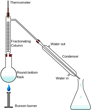
Figure 1: Fractional distillation apparatus using a Liebig condenser.
 
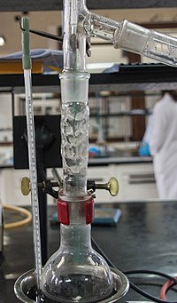
Vigreux column in a laboratory setup

A laboratory fractionating column is a piece of glassware used to separate vaporized mixtures of liquid compounds with close volatility. Most commonly used is either a Vigreux column or a straight column packed with glass beads or metal pieces such as Raschig rings. Fractionating columns help to separate the mixture by allowing the mixed vapors to cool, condense, and vaporize again in accordance with Raoult's law. With each condensation-vaporization cycle, the vapors are enriched in a certain component. A larger surface area allows more cycles, improving separation. This is the rationale for a Vigreux column or a packed fractionating column. Spinning band distillation achieves the same outcome by using a rotating band within the column to force the rising vapors and descending condensate into close contact, achieving equilibrium more quickly.

In a typical fractional distillation, a liquid mixture is heated in the distilling flask, and the resulting vapor rises up the fractionating column (see Figure 1). The vapor condenses on glass spurs (known as theoretical trays or theoretical plates) inside the column, and returns to the distilling flask, refluxing the rising distillate vapor. The hottest tray is at the bottom of the column and the coolest tray is at the top. At steady-state conditions, the vapor and liquid on each tray reach an equilibrium. Only the most volatile of the vapors stays in gas form all the way to the top, where it may then proceed through a condenser, which cools the vapor until it condenses into a liquid distillate. The separation may be enhanced by the addition of more trays (to a practical limitation of heat, flow, etc.).

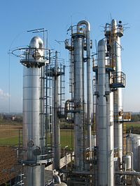
Figure 2: Typical industrial fractionating columns

Industrial fractionating columns

Fractional distillation is one of the unit operations of chemical engineering. Fractionating columns are widely used in chemical process industries where large quantities of liquids have to be distilled. Such industries are petroleum processing, petrochemical production, natural gas processing, coal tar processing, brewing, liquefied air separation, and hydrocarbon solvents production. Fractional distillation finds its widest application in petroleum refineries. In such refineries, the crude oil feedstock is a complex, multicomponent mixture that must be separated. Yields of pure chemical compounds are generally not expected, however, yields of groups of compounds within a relatively small range of boiling points, also called fractions, are expected. This process is the origin of the name fractional distillation or fractionation.

Distillation is one of the most common and energy-intensive separation processes. Effectiveness of separation is dependent upon the height and diameter of the column, the ratio of the column's height to diameter, and the material that comprises the distillation column itself. In a typical chemical plant, it accounts for about 40% of the total energy consumption. Industrial distillation is typically performed in large, vertical cylindrical columns (as shown in Figure 2) known as "distillation towers" or "distillation columns" with diameters ranging from about 65 centimeters to 6 meters and heights ranging from about 6 meters to 60 meters or more.

Figure 3: Chemical engineering schematic of a continuous fractionating column
 
Figure 4: Chemical engineering schematic of typical bubble-cap trays in a fractionating column

Industrial distillation towers are usually operated at a continuous steady state. Unless disturbed by changes in feed, heat, ambient temperature, or condensing, the amount of feed being added normally equals the amount of product being removed.

The amount of heat entering the column from the reboiler and with the feed must equal the amount heat removed by the overhead condenser and with the products. The heat entering a distillation column is a crucial operating parameter, addition of excess or insufficient heat to the column can lead to foaming, weeping, entrainment, or flooding.

Figure 3 depicts an industrial fractionating column separating a feed stream into one distillate fraction and one bottoms fraction. However, many industrial fractionating columns have outlets at intervals up the column so that multiple products having different boiling ranges may be withdrawn from a column distilling a multi-component feed stream. The "lightest" products with the lowest boiling points exit from the top of the columns and the "heaviest" products with the highest boiling points exit from the bottom.

Industrial fractionating columns use external reflux to achieve better separation of products. Reflux refers to the portion of the condensed overhead liquid product that returns to the upper part of the fractionating column as shown in Figure 3.

Inside the column, the downflowing reflux liquid provides cooling and condensation of upflowing vapors thereby increasing the efficacy of the distillation tower. The more reflux and/or more trays provided, the better is the tower's separation of lower boiling materials from higher boiling materials.

The design and operation of a fractionating column depends on the composition of the feed as well as the composition of the desired products. Given a simple, binary component feed, analytical methods such as the McCabe–Thiele method or the Fenske equation can be used. For a multi-component feed, simulation models are used both for design, operation, and construction.

Bubble-cap "trays" or "plates" are one of the types of physical devices, which are used to provide good contact between the upflowing vapor and the downflowing liquid inside an industrial fractionating column. Such trays are shown in Figures 4 and 5.

The efficiency of a tray or plate is typically lower than that of a theoretical 100% efficient equilibrium stage. Hence, a fractionating column almost always needs more actual, physical plates than the required number of theoretical vapor–liquid equilibrium stages.

Figure 5: Section of fractionating tower of Figure 4 showing detail of a pair of trays with bubble caps
 
Figure 6: Entire view of a Distillation Column

In industrial uses, sometimes a packing material is used in the column instead of trays, especially when low pressure drops across the column are required, as when operating under vacuum. This packing material can either be random dumped packing (1–3 in or 2.5–7.6 cm wide) such as Raschig rings or structured sheet metal. Liquids tend to wet the surface of the packing, and the vapors pass across this wetted surface, where mass transfer takes place. Differently shaped packings have different surface areas and void space between packings. Both of these factors affect packing performance.

Conductivity (electrolytic)

From Wikipedia, the free encyclopedia

Conductivity (or specific conductance) of an electrolyte solution is a measure of its ability to conduct electricity. The SI unit of conductivity is Siemens per meter (S/m).

Conductivity measurements are used routinely in many industrial and environmental applications as a fast, inexpensive and reliable way of measuring the ionic content in a solution. For example, the measurement of product conductivity is a typical way to monitor and continuously trend the performance of water purification systems.

The electrolytic conductivity of ultra-high purity water increases as a function of temperature (T) due to the higher dissociation of H2O in H+ and OH with T.

In many cases, conductivity is linked directly to the total dissolved solids (TDS). High quality deionized water has a conductivity of about 0.05 μS/cm at 25 °C, typical drinking water is in the range of 200–800 μS/cm, while sea water is about 50 mS/cm (or 0.05 S/cm).

Conductivity is traditionally determined by connecting the electrolyte in a Wheatstone bridge. Dilute solutions follow Kohlrausch's Laws of concentration dependence and additivity of ionic contributions. Lars Onsager gave a theoretical explanation of Kohlrausch's law by extending Debye–Hückel theory.

Units

The SI unit of conductivity is S/m and, unless otherwise qualified, it refers to 25 °C. More generally encountered is the traditional unit of μS/cm.

The commonly used standard cell has a width of 1 cm, and thus for very pure water in equilibrium with air would have a resistance of about 106 ohms, known as a megohm. Ultra-pure water could achieve 18 megohms or more. Thus in the past, megohm-cm was used, sometimes abbreviated to "megohm". Sometimes, conductivity is given in "microsiemens" (omitting the distance term in the unit). While this is an error, it can often be assumed to be equal to the traditional μS/cm. Often, by typographic limitations μS/cm is expressed as uS/cm.

The conversion of conductivity to the total dissolved solids depends on the chemical composition of the sample and can vary between 0.54 and 0.96. Typically, the conversion is done assuming that the solid is sodium chloride; 1 μS/cm is then equivalent to about 0.64 mg of NaCl per kg of water.

Molar conductivity has the SI unit S m2 mol−1. Older publications use the unit Ω−1 cm2 mol−1.

Measurement

Principle of the measurement

The electrical conductivity of a solution of an electrolyte is measured by determining the resistance of the solution between two flat or cylindrical electrodes separated by a fixed distance. An alternating voltage is generally used in order to minimize water electrolysis. The resistance is measured by a conductivity meter. Typical frequencies used are in the range 1–3 kHz. The dependence on the frequency is usually small, but may become appreciable at very high frequencies, an effect known as the Debye–Falkenhagen effect.

A wide variety of instrumentation is commercially available. Most commonly, two types of electrode sensors are used, electrode-based sensors and inductive sensors. Electrode sensors with a static design are suitable for low and moderate conductivities, and exist in various types, having either two or four electrodes, where electrodes can be arrange oppositely, flat or in a cylinder. Electrode cells with a flexible design, where the distance between two oppositely arranged electrodes can be varied, offer high accuracy and can also be used for the measurement of highly conductive media. Inductive sensors are suitable for harsh chemical conditions but require larger sample volumes than electrode sensors. Conductivity sensors are typically calibrated with KCl solutions of known conductivity. Electrolytic conductivity is highly temperature dependent but many commercial systems offer automatic temperature correction. Tables of reference conductivities are available for many common solutions.

Definitions

Resistance, R, is proportional to the distance, l, between the electrodes and is inversely proportional to the cross-sectional area of the sample, A (noted S on the Figure above). Writing ρ (rho) for the specific resistance, or resistivity.

In practice the conductivity cell is calibrated by using solutions of known specific resistance, ρ*, so the individual quantities l and A need not be known precisely, but only their ratio. If the resistance of the calibration solution is R*, a cell-constant, defined as the ratio of l and A (C = lA), is derived.

The specific conductance (conductivity), κ (kappa) is the reciprocal of the specific resistance.

Conductivity is also temperature-dependent. Sometimes the conductance (reciprocical of the resistance) is denoted as G = 1R. Then the specific conductance κ (kappa) is:

Theory

The specific conductance of a solution containing one electrolyte depends on the concentration of the electrolyte. Therefore, it is convenient to divide the specific conductance by concentration. This quotient, termed molar conductivity, is denoted by Λm

Strong electrolytes

Strong electrolytes are hypothesized to dissociate completely in solution. The conductivity of a solution of a strong electrolyte at low concentration follows Kohlrausch's Law

where Λ0
m
is known as the limiting molar conductivity, K is an empirical constant and c is the electrolyte concentration. (Limiting here means "at the limit of the infinite dilution".) In effect, the observed conductivity of a strong electrolyte becomes directly proportional to concentration, at sufficiently low concentrations i.e. when

As the concentration is increased however, the conductivity no longer rises in proportion. Moreover, Kohlrausch also found that the limiting conductivity of an electrolyte;

λ0
+
and λ0
are the limiting molar conductivities of the individual ions.

The following table gives values for the limiting molar conductivities for some selected ions.

Table of limiting ion conductivity in water at 298 K (approx. 25 °C)
Cations λ0
+
/ mS m2 mol−1
Cations λ0
+
/ mS m2 mol−1
Anions λ0
/ mS m2 mol−1
Anions λ0
/ mS m2 mol−1
H+ 34.982 Ba2+ 12.728 OH 19.8 SO2−
4
15.96
Li+ 3.869 Mg2+ 10.612 Cl 7.634 C
2
O2−
4
7.4
Na+ 5.011 La3+ 20.88 Br 7.84 HC
2
O
4
4.306
K+ 7.352 Rb+ 7.64 I 7.68 HCOO 5.6
NH+
4
7.34 Cs+ 7.68 NO
3
7.144 CO2−
3
7.2
Ag+ 6.192 Be2+ 4.50 CH3COO 4.09 HSO2−
3
5.0
Ca2+ 11.90

ClO
4
6.80 SO2−
3
7.2
Co(NH
3
)3+
6
10.2

F 5.50

An interpretation of these results was based on the theory of Debye and Hückel, yielding the Debye–Hückel–Onsager theory:

where A and B are constants that depend only on known quantities such as temperature, the charges on the ions and the dielectric constant and viscosity of the solvent. As the name suggests, this is an extension of the Debye–Hückel theory, due to Onsager. It is very successful for solutions at low concentration.

Weak electrolytes

A weak electrolyte is one that is never fully dissociated (there are a mixture of ions and complete molecules in equilibrium). In this case there is no limit of dilution below which the relationship between conductivity and concentration becomes linear. Instead, the solution becomes ever more fully dissociated at weaker concentrations, and for low concentrations of "well behaved" weak electrolytes, the degree of dissociation of the weak electrolyte becomes proportional to the inverse square root of the concentration.

Typical weak electrolytes are weak acids and weak bases. The concentration of ions in a solution of a weak electrolyte is less than the concentration of the electrolyte itself. For acids and bases the concentrations can be calculated when the value or values of the acid dissociation constant are known.

For a monoprotic acid, HA, obeying the inverse square root law, with a dissociation constant Ka, an explicit expression for the conductivity as a function of concentration, c, known as Ostwald's dilution law, can be obtained.

Various solvents exhibit the same dissociation if the ratio of relative permittivities equals the ratio cubic roots of concentrations of the electrolytes (Walden's rule).

Higher concentrations

Both Kohlrausch's law and the Debye–Hückel–Onsager equation break down as the concentration of the electrolyte increases above a certain value. The reason for this is that as concentration increases the average distance between cation and anion decreases, so that there is more interactions between close ions. Whether this constitutes ion association is a moot point. However, it has often been assumed that cation and anion interact to form an ion pair. So, an "ion-association" constant K, can be derived for the association equilibrium between ions A+ and B:

A+ + B ⇌ A+B   with   K = [A+B]/[A+] [B]

Davies describes the results of such calculations in great detail, but states that K should not necessarily be thought of as a true equilibrium constant, rather, the inclusion of an "ion-association" term is useful in extending the range of good agreement between theory and experimental conductivity data. Various attempts have been made to extend Onsager's treatment to more concentrated solutions.

The existence of a so-called conductance minimum in solvents having the relative permittivity under 60 has proved to be a controversial subject as regards interpretation. Fuoss and Kraus suggested that it is caused by the formation of ion triplets, and this suggestion has received some support recently.

Other developments on this topic have been done by Theodore Shedlovsky, E. Pitts, R. M. Fuoss, Fuoss and Shedlovsky, Fuoss and Onsager.

Mixed solvents systems

The limiting equivalent conductivity of solutions based on mixed solvents like water alcohol has minima depending on the nature of alcohol. For methanol the minimum is at 15 molar % water, and for the ethanol at 6 molar % water.

Conductivity versus temperature

Generally the conductivity of a solution increases with temperature, as the mobility of the ions increases. For comparison purposes reference values are reported at an agreed temperature, usually 298 K (≈ 25 °C or 77 °F), although occasionally 20 °C (68 °F) is used. So called 'compensated' measurements are made at a convenient temperature but the value reported is a calculated value of the expected value of conductivity of the solution, as if it had been measured at the reference temperature. Basic compensation is normally done by assuming a linear increase of conductivity versus temperature of typically 2% per kelvin. This value is broadly applicable for most salts at room temperature. Determination of the precise temperature coefficient for a specific solution is simple and instruments are typically capable of applying the derived coefficient (i.e. other than 2%).

Measurements of conductivity versus temperature can be used to determine the activation energy , using the Arrhenius equation:

where is the exponential prefactor, R the gas constant, and T the absolute temperature in Kelvin.

Solvent isotopic effect

The change in conductivity due to the isotope effect for deuterated electrolytes is sizable.

Applications

Despite the difficulty of theoretical interpretation, measured conductivity is a good indicator of the presence or absence of conductive ions in solution, and measurements are used extensively in many industries. For example, conductivity measurements are used to monitor quality in public water supplies, in hospitals, in boiler water and industries that depend on water quality such as brewing. This type of measurement is not ion-specific; it can sometimes be used to determine the amount of total dissolved solids (TDS) if the composition of the solution and its conductivity behavior are known. Conductivity measurements made to determine water purity will not respond to non conductive contaminants (many organic compounds fall into this category), therefore additional purity tests may be required depending on application.

Applications of TDS measurements are not limited to industrial use; many people use TDS as an indicator of the purity of their drinking water. Additionally, aquarium enthusiasts are concerned with TDS, both for freshwater and salt water aquariums. Many fish and invertebrates require quite narrow parameters for dissolved solids. Especially for successful breeding of some invertebrates normally kept in freshwater aquariums—snails and shrimp primarily—brackish water with higher TDS, specifically higher salinity, water is required. While the adults of a given species may thrive in freshwater, this is not always true for the young and some species will not breed at all in non-brackish water.

Sometimes, conductivity measurements are linked with other methods to increase the sensitivity of detection of specific types of ions. For example, in the boiler water technology, the boiler blowdown is continuously monitored for "cation conductivity", which is the conductivity of the water after it has been passed through a cation exchange resin. This is a sensitive method of monitoring anion impurities in the boiler water in the presence of excess cations (those of the alkalizing agent usually used for water treatment). The sensitivity of this method relies on the high mobility of H+ in comparison with the mobility of other cations or anions. Beyond cation conductivity, there are analytical instruments designed to measure Degas conductivity, where conductivity is measured after dissolved carbon dioxide has been removed from the sample, either through reboiling or dynamic degassing.

Conductivity detectors are commonly used with ion chromatography.

Fractional distillation

From Wikipedia, the free encyclopedia

Fractional distillation is the separation of a mixture into its component parts, or fractions. Chemical compounds are separated by heating them to a temperature at which one or more fractions of the mixture will vaporize. It uses distillation to fractionate. Generally the component parts have boiling points that differ by less than 25 °C (45 °F) from each other under a pressure of one atmosphere. If the difference in boiling points is greater than 25 °C, a simple distillation is typically used. It is used to refine crude oil.

Laboratory setup

Fractional distillation in a laboratory makes use of common laboratory glassware and apparatuses, typically including a Bunsen burner, a round-bottomed flask and a condenser, as well as the single-purpose fractionating column.

Fractional distillation

As an example, consider the distillation of a mixture of water and ethanol. Ethanol boils at 78.4 °C (173.1 °F) while water boils at 100 °C (212 °F). So, by heating the mixture, the most volatile component (ethanol) will concentrate to a greater degree in the vapor leaving the liquid. Some mixtures form azeotropes, where the mixture boils at a lower temperature than either component. In this example, a mixture of 96% ethanol and 4% water boils at 78.2 °C (172.8 °F); the mixture is more volatile than pure ethanol. For this reason, ethanol cannot be completely purified by direct fractional distillation of ethanol-water mixtures.

The apparatus is assembled as in the diagram. (The diagram represents a batch apparatus as opposed to a continuous apparatus.) The mixture is put into the round-bottomed flask along with a few anti-bumping granules (or a Teflon coated magnetic stirrer bar if using magnetic stirring), and the fractionating column is fitted into the top. The fractional distillation column is set up with the heat source at the bottom of the still pot. As the distance from the still pot increases, a temperature gradient is formed in the column; it is coolest at the top and hottest at the bottom. As the mixed vapor ascends the temperature gradient, some of the vapor condenses and vaporizes along the temperature gradient. Each time the vapor condenses and vaporizes, the composition of the more volatile component in the vapor increases. This distills the vapor along the length of the column, and eventually, the vapor is composed solely of the more volatile component (or an azeotrope). The vapor condenses on the glass platforms, known as trays, inside the column, and runs back down into the liquid below, refluxing distillate. The efficiency in terms of the amount of heating and time required to get fractionation can be improved by insulating the outside of the column in an insulator such as wool, aluminum foil, or preferably a vacuum jacket. The hottest tray is at the bottom and the coolest is at the top. At steady-state conditions, the vapor and liquid on each tray are at equilibrium. The most volatile component of the mixture exits as a gas at the top of the column. The vapor at the top of the column then passes into the condenser, which cools it down until it liquefies. The separation is more pure with the addition of more trays (to a practical limitation of heat, flow, etc.) Initially, the condensate will be close to the azeotropic composition, but when much of the ethanol has been drawn off, the condensate becomes gradually richer in water. The process continues until all the ethanol boils out of the mixture. This point can be recognized by the sharp rise in temperature shown on the thermometer.

The above explanation reflects the theoretical way fractionation works. Normal laboratory fractionation columns will be simple glass tubes (often vacuum-jacketed, and sometimes internally silvered) filled with a packing, often small glass helices of 4 to 7 millimetres (0.16 to 0.28 in) diameter. Such a column can be calibrated by the distillation of a known mixture system to quantify the column in terms of number of theoretical trays. To improve fractionation the apparatus is set up to return condensate to the column by the use of some sort of reflux splitter (reflux wire, gago, Magnetic swinging bucket, etc.) - a typical careful fractionation would employ a reflux ratio of around 4:1 (4 parts returned condensate to 1 part condensate take off).

In laboratory distillation, several types of condensers are commonly found. The Liebig condenser is simply a straight tube within a water jacket and is the simplest (and relatively least expensive) form of condenser. The Graham condenser is a spiral tube within a water jacket, and the Allihn condenser has a series of large and small constrictions on the inside tube, each increasing the surface area upon which the vapor constituents may condense.

Alternate set-ups may use a multi-outlet distillation receiver flask (referred to as a "cow" or "pig") to connect three or four receiving flasks to the condenser. By turning the cow or pig, the distillates can be channeled into any chosen receiver. Because the receiver does not have to be removed and replaced during the distillation process, this type of apparatus is useful when distilling under an inert atmosphere for air-sensitive chemicals or at reduced pressure. A Perkin triangle is an alternative apparatus often used in these situations because it allows isolation of the receiver from the rest of the system, but does require removing and reattaching a single receiver for each fraction.

Vacuum distillation systems operate at reduced pressure, thereby lowering the boiling points of the materials. Anti-bumping granules, however, become ineffective at reduced pressures.

Industrial distillation

Typical industrial fractional distillation columns

Fractional distillation is the most common form of separation technology used in petroleum refineries, petrochemical and chemical plants, natural gas processing and cryogenic air separation plants. In most cases, the distillation is operated at a continuous steady state. New feed is always being added to the distillation column and products are always being removed. Unless the process is disturbed due to changes in feed, heat, ambient temperature, or condensing, the amount of feed being added and the amount of product being removed are normally equal. This is known as continuous, steady-state fractional distillation.

Industrial distillation is typically performed in large, vertical cylindrical columns known as "distillation or fractionation towers" or "distillation columns" with diameters ranging from about 0.65 to 6 meters (2 to 20 ft) and heights ranging from about 6 to 60 meters (20 to 197 ft) or more. The distillation towers have liquid outlets at intervals up the column which allow for the withdrawal of different fractions or products having different boiling points or boiling ranges. By increasing the temperature of the product inside the columns, the different products are separated. The "lightest" products (those with the lowest boiling point) exit from the top of the columns and the "heaviest" products (those with the highest boiling point) exit from the bottom of the column.

For example, fractional distillation is used in oil refineries to separate crude oil into useful substances (or fractions) having different hydrocarbons of different boiling points. The crude oil fractions with higher boiling points:

Diagram of a typical industrial distillation tower

Large-scale industrial towers use reflux to achieve a more complete separation of products. Reflux refers to the portion of the condensed overhead liquid product from a distillation or fractionation tower that is returned to the upper part of the tower as shown in the schematic diagram of a typical, large-scale industrial distillation tower. Inside the tower, the reflux liquid flowing downwards provides the cooling needed to condense the vapors flowing upwards, thereby increasing the effectiveness of the distillation tower. The more reflux is provided for a given number of theoretical plates, the better the tower's separation of lower boiling materials from higher boiling materials. Alternatively, the more reflux provided for a given desired separation, the fewer theoretical plates are required.

Crude oil is separated into fractions by fractional distillation. The fractions at the top of the fractionating column have lower boiling points than the fractions at the bottom. All of the fractions are processed further in other refining units.

Fractional distillation is also used in air separation, producing liquid oxygen, liquid nitrogen, and highly concentrated argon. Distillation of chlorosilanes also enable the production of high-purity silicon for use as a semiconductor.

In industrial uses, sometimes a packing material is used in the column instead of trays, especially when low-pressure drops across the column are required, as when operating under vacuum. This packing material can either be random dumped packing (1–3 in (25–76 mm) wide) such as Raschig rings or structured sheet metal. Typical manufacturers are Koch, Sulzer, and other companies. Liquids tend to wet the surface of the packing and the vapors pass across this wetted surface, where mass transfer takes place. Unlike conventional tray distillation in which every tray represents a separate point of vapor liquid equilibrium the vapor-liquid equilibrium curve in a packed column is continuous. However, when modeling packed columns it is useful to compute several "theoretical plates" to denote the separation efficiency of the packed column concerning more traditional trays. Differently shaped packings have different surface areas and porosity. Both of these factors affect packing performance.

Design of industrial distillation columns

Chemical engineering schematic of typical bubble-cap trays in a distillation tower

Design and operation of a distillation column depends on the feed and desired products. Given a simple, binary component feed, analytical methods such as the McCabe–Thiele method or the Fenske equation can be used. For a multi-component feed, simulation models are used both for design and operation.

Moreover, the efficiencies of the vapor-liquid contact devices (referred to as plates or trays) used in distillation columns are typically lower than that of a theoretical 100% efficient equilibrium stage. Hence, a distillation column needs more plates than the number of theoretical vapor-liquid equilibrium stages.

Reflux refers to the portion of the condensed overhead product that is returned to the tower. The reflux flowing downwards provides the cooling required for condensing the vapors flowing upwards. The reflux ratio, which is the ratio of the (internal) reflux to the overhead product, is conversely related to the theoretical number of stages required for efficient separation of the distillation products. Fractional distillation towers or columns are designed to achieve the required separation efficiently. The design of fractionation columns is normally made in two steps; a process design, followed by a mechanical design. The purpose of the process design is to calculate the number of required theoretical stages and stream flows including the reflux ratio, heat reflux, and other heat duties. The purpose of the mechanical design, on the other hand, is to select the tower internals, column diameter, and height. In most cases, the mechanical design of fractionation towers is not straightforward. For the efficient selection of tower internals and the accurate calculation of column height and diameter, many factors must be taken into account. Some of the factors involved in design calculations include feed load size and properties and the type of distillation column used.

The two major types of distillation columns used are tray and packing columns. Packing columns are normally used for smaller towers and loads that are corrosive or temperature-sensitive or for vacuum service where pressure drop is important. Tray columns, on the other hand, are used for larger columns with high liquid loads. They first appeared on the scene in the 1820s. In most oil refinery operations, tray columns are mainly used for the separation of petroleum fractions at different stages of oil refining.

In the oil refining industry, the design and operation of fractionation towers is still largely accomplished on an empirical basis. The calculations involved in the design of petroleum fractionation columns require in the usual practice the use of numerable charts, tables, and complex empirical equations. In recent years, however, a considerable amount of work has been done to develop efficient and reliable computer-aided design procedures for fractional distillation.

History

The fractional distillation of organic substances played an important role in the 9th-century works attributed to the Islamic alchemist Jabir ibn Hayyan, as for example in the Kitāb al-Sabʿīn ('The Book of Seventy'), translated into Latin by Gerard of Cremona (c. 1114–1187) under the title Liber de septuaginta. The Jabirian experiments with fractional distillation of animal and vegetable substances, and to a lesser degree also of mineral substances, formed the main topic of the De anima in arte alkimiae, an originally Arabic work falsely attributed to Avicenna that was translated into Latin and would go on to form the most important alchemical source for Roger Bacon (c. 1220–1292).

Politics of Europe

From Wikipedia, the free encyclopedia ...