Search This Blog

Tuesday, October 24, 2023

Tidal locking

From Wikipedia, the free encyclopedia
https://en.wikipedia.org/wiki/Tidal_locking
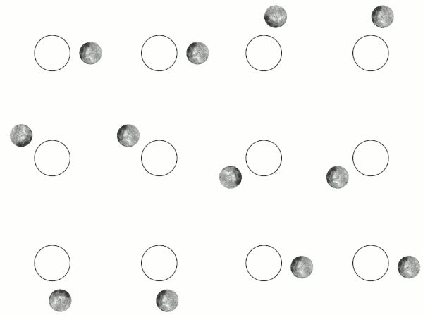
Tidal locking results in the Moon rotating about its axis in about the same time it takes to orbit Earth. Except for libration, this results in the Moon keeping the same face turned toward Earth, as seen in the left figure. The Moon is shown in polar view, and is not drawn to scale. If the Moon were not rotating at all, it would alternately show its near and far sides to Earth, while moving around Earth in orbit, as shown in the right figure.
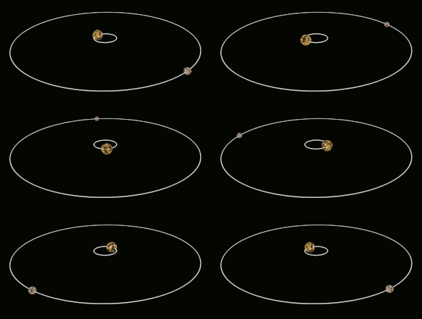
A side view of the Pluto–Charon system. Pluto and Charon are tidally locked to each other. Charon is massive enough that the barycenter of Pluto's system lies outside of Pluto; thus, Pluto and Charon are sometimes considered to be a binary system.

Tidal locking between a pair of co-orbiting astronomical bodies occurs when one of the objects reaches a state where there is no longer any net change in its rotation rate over the course of a complete orbit. In the case where a tidally locked body possesses synchronous rotation, the object takes just as long to rotate around its own axis as it does to revolve around its partner. For example, the same side of the Moon always faces the Earth, although there is some variability because the Moon's orbit is not perfectly circular. Usually, only the satellite is tidally locked to the larger body. However, if both the difference in mass between the two bodies and the distance between them are relatively small, each may be tidally locked to the other; this is the case for Pluto and Charon, as well as for Eris and Dysnomia. Alternative names for the tidal locking process are gravitational locking, captured rotation, and spin–orbit locking.

The effect arises between two bodies when their gravitational interaction slows a body's rotation until it becomes tidally locked. Over many millions of years, the interaction forces changes to their orbits and rotation rates as a result of energy exchange and heat dissipation. When one of the bodies reaches a state where there is no longer any net change in its rotation rate over the course of a complete orbit, it is said to be tidally locked. The object tends to stay in this state because leaving it would require adding energy back into the system. The object's orbit may migrate over time so as to undo the tidal lock, for example, if a giant planet perturbs the object.

Not every case of tidal locking involves synchronous rotation. With Mercury, for example, this tidally locked planet completes three rotations for every two revolutions around the Sun, a 3:2 spin–orbit resonance. In the special case where an orbit is nearly circular and the body's rotation axis is not significantly tilted, such as the Moon, tidal locking results in the same hemisphere of the revolving object constantly facing its partner. However, in this case the exact same portion of the body does not always face the partner on all orbits. There can be some shifting due to variations in the locked body's orbital velocity and the inclination of its rotation axis.

Mechanism

If the tidal bulges on a body (green) are misaligned with the major axis (red), the tidal forces (blue) exert a net torque on that body that twists the body toward the direction of realignment.

Consider a pair of co-orbiting objects, A and B. The change in rotation rate necessary to tidally lock body B to the larger body A is caused by the torque applied by A's gravity on bulges it has induced on B by tidal forces.

The gravitational force from object A upon B will vary with distance, being greatest at the nearest surface to A and least at the most distant. This creates a gravitational gradient across object B that will distort its equilibrium shape slightly. The body of object B will become elongated along the axis oriented toward A, and conversely, slightly reduced in dimension in directions orthogonal to this axis. The elongated distortions are known as tidal bulges. (For the solid Earth, these bulges can reach displacements of up to around 0.4 m or 1 ft 4 in.) When B is not yet tidally locked, the bulges travel over its surface due to orbital motions, with one of the two "high" tidal bulges traveling close to the point where body A is overhead. For large astronomical bodies that are nearly spherical due to self-gravitation, the tidal distortion produces a slightly prolate spheroid, i.e. an axially symmetric ellipsoid that is elongated along its major axis. Smaller bodies also experience distortion, but this distortion is less regular.

The material of B exerts resistance to this periodic reshaping caused by the tidal force. In effect, some time is required to reshape B to the gravitational equilibrium shape, by which time the forming bulges have already been carried some distance away from the A–B axis by B's rotation. Seen from a vantage point in space, the points of maximum bulge extension are displaced from the axis oriented toward A. If B's rotation period is shorter than its orbital period, the bulges are carried forward of the axis oriented toward A in the direction of rotation, whereas if B's rotation period is longer, the bulges instead lag behind.

Because the bulges are now displaced from the A–B axis, A's gravitational pull on the mass in them exerts a torque on B. The torque on the A-facing bulge acts to bring B's rotation in line with its orbital period, whereas the "back" bulge, which faces away from A, acts in the opposite sense. However, the bulge on the A-facing side is closer to A than the back bulge by a distance of approximately B's diameter, and so experiences a slightly stronger gravitational force and torque. The net resulting torque from both bulges, then, is always in the direction that acts to synchronize B's rotation with its orbital period, leading eventually to tidal locking.

Orbital changes
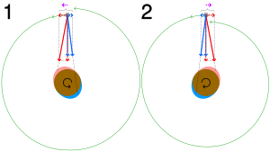
In (1), a satellite orbits in the same direction as (but slower than) its parent body's rotation. The nearer tidal bulge (red) attracts the satellite more than the farther bulge (blue), slowing the parent's rotation while imparting a net positive force (dotted arrows showing forces resolved into their components) in the direction of orbit, lifting it into a higher orbit (tidal acceleration).
In (2) with the rotation reversed, the net force opposes the satellite's direction of orbit, lowering it (tidal deceleration).
Tidal Locking
If rotational frequency is larger than orbital frequency, a small torque counteracting the rotation arises, eventually locking the frequencies (situation depicted in green)

The angular momentum of the whole A–B system is conserved in this process, so that when B slows down and loses rotational angular momentum, its orbital angular momentum is boosted by a similar amount (there are also some smaller effects on A's rotation). This results in a raising of B's orbit about A in tandem with its rotational slowdown. For the other case where B starts off rotating too slowly, tidal locking both speeds up its rotation, and lowers its orbit.

Locking of the larger body

The tidal locking effect is also experienced by the larger body A, but at a slower rate because B's gravitational effect is weaker due to B's smaller mass. For example, Earth's rotation is gradually being slowed by the Moon, by an amount that becomes noticeable over geological time as revealed in the fossil record. Current estimations are that this (together with the tidal influence of the Sun) has helped lengthen the Earth day from about 6 hours to the current 24 hours (over ≈ ⁠4½ billion years). Currently, atomic clocks show that Earth's day lengthens, on average, by about 2.3 milliseconds per century. Given enough time, this would create a mutual tidal locking between Earth and the Moon. The length of the Earth's day would increase and the length of a lunar month would also increase. The Earth's sidereal day would eventually have the same length as the Moon's orbital period, about 47 times the length of the Earth's day at present. However, Earth is not expected to become tidally locked to the Moon before the Sun becomes a red giant and engulfs Earth and the Moon.

For bodies of similar size the effect may be of comparable size for both, and both may become tidally locked to each other on a much shorter timescale. An example is the dwarf planet Pluto and its satellite Charon. They have already reached a state where Charon is visible from only one hemisphere of Pluto and vice versa.

Eccentric orbits

A widely spread misapprehension is that a tidally locked body permanently turns one side to its host.

— Heller et al. (2011)

For orbits that do not have an eccentricity close to zero, the rotation rate tends to become locked with the orbital speed when the body is at periapsis, which is the point of strongest tidal interaction between the two objects. If the orbiting object has a companion, this third body can cause the rotation rate of the parent object to vary in an oscillatory manner. This interaction can also drive an increase in orbital eccentricity of the orbiting object around the primary – an effect known as eccentricity pumping.

In some cases where the orbit is eccentric and the tidal effect is relatively weak, the smaller body may end up in a so-called spin–orbit resonance, rather than being tidally locked. Here, the ratio of the rotation period of a body to its own orbital period is some simple fraction different from 1:1. A well known case is the rotation of Mercury, which is locked to its own orbit around the Sun in a 3:2 resonance. This results in the rotation speed roughly matching the orbital speed around perihelion.

Many exoplanets (especially the close-in ones) are expected to be in spin–orbit resonances higher than 1:1. A Mercury-like terrestrial planet can, for example, become captured in a 3:2, 2:1, or 5:2 spin–orbit resonance, with the probability of each being dependent on the orbital eccentricity.

Occurrence

Moons

Due to tidal locking, the inhabitants of the central body will never be able to see the satellite's green area.

All twenty known moons in the Solar System that are large enough to be round are tidally locked with their primaries, because they orbit very closely and tidal force increases rapidly (as a cubic function) with decreasing distance. On the other hand, the irregular outer satellites of the gas giants (e.g. Phoebe), which orbit much farther away than the large well-known moons, are not tidally locked.

Pluto and Charon are an extreme example of a tidal lock. Charon is a relatively large moon in comparison to its primary and also has a very close orbit. This results in Pluto and Charon being mutually tidally locked. Pluto's other moons are not tidally locked; Styx, Nix, Kerberos, and Hydra all rotate chaotically due to the influence of Charon. Similarly, Eris and Dysnomia are mutually tidally locked. Orcus and Vanth might also be mutually tidally locked, but the data is not conclusive.

The tidal locking situation for asteroid moons is largely unknown, but closely orbiting binaries are expected to be tidally locked, as well as contact binaries.

Earth's Moon

Libration causes variability in the portion of the Moon visible from Earth.

Earth's Moon's rotation and orbital periods are tidally locked with each other, so no matter when the Moon is observed from Earth, the same hemisphere of the Moon is always seen. Most of the far side of the Moon was not seen until 1959, when photographs of most of the far side were transmitted from the Soviet spacecraft Luna 3.

When the Earth is observed from the Moon, the Earth does not appear to move across the sky. It remains in the same place while showing nearly all its surface as it rotates on its axis.

Despite the Moon's rotational and orbital periods being exactly locked, about 59 percent of the Moon's total surface may be seen with repeated observations from Earth, due to the phenomena of libration and parallax. Librations are primarily caused by the Moon's varying orbital speed due to the eccentricity of its orbit: this allows up to about 6° more along its perimeter to be seen from Earth. Parallax is a geometric effect: at the surface of Earth observers are offset from the line through the centers of Earth and Moon, and because of this about 1° more can be seen around the side of the Moon when it is on the local horizon.

Planets

It was thought for some time that Mercury was in synchronous rotation with the Sun. This was because whenever Mercury was best placed for observation, the same side faced inward. Radar observations in 1965 demonstrated instead that Mercury has a 3:2 spin–orbit resonance, rotating three times for every two revolutions around the Sun, which results in the same positioning at those observation points. Modeling has demonstrated that Mercury was captured into the 3:2 spin–orbit state very early in its history, probably within 10–20 million years after its formation.

The 583.92-day interval between successive close approaches of Venus to Earth is equal to 5.001444 Venusian solar days, making approximately the same face visible from Earth at each close approach. Whether this relationship arose by chance or is the result of some kind of tidal locking with Earth is unknown.

The exoplanet Proxima Centauri b discovered in 2016 which orbits around Proxima Centauri, is almost certainly tidally locked, expressing either synchronized rotation or a 3:2 spin–orbit resonance like that of Mercury.

One form of hypothetical tidally locked exoplanets are eyeball planets, which in turn are divided into "hot" and "cold" eyeball planets.

Stars

Close binary stars throughout the universe are expected to be tidally locked with each other, and extrasolar planets that have been found to orbit their primaries extremely closely are also thought to be tidally locked to them. An unusual example, confirmed by MOST, may be Tau Boötis, a star that is probably tidally locked by its planet Tau Boötis b. If so, the tidal locking is almost certainly mutual.

Timescale

An estimate of the time for a body to become tidally locked can be obtained using the following formula:

where

  • is the initial spin rate expressed in radians per second,
  • is the semi-major axis of the motion of the satellite around the planet (given by the average of the periapsis and apoapsis distances),
  • is the moment of inertia of the satellite, where is the mass of the satellite and is the mean radius of the satellite,
  • is the dissipation function of the satellite,
  • is the gravitational constant,
  • is the mass of the planet (i.e., the object being orbited), and
  • is the tidal Love number of the satellite.

and are generally very poorly known except for the Moon, which has . For a really rough estimate it is common to take (perhaps conservatively, giving overestimated locking times), and

where

  • is the density of the satellite
  • is the surface gravity of the satellite
  • is the rigidity of the satellite. This can be roughly taken as 3×10¹⁰ N·m−2 for rocky objects and 4×10⁹ N·m−2 for icy ones.

Even knowing the size and density of the satellite leaves many parameters that must be estimated (especially ω, Q, and μ), so that any calculated locking times obtained are expected to be inaccurate, even to factors of ten. Further, during the tidal locking phase the semi-major axis may have been significantly different from that observed nowadays due to subsequent tidal acceleration, and the locking time is extremely sensitive to this value.

Because the uncertainty is so high, the above formulas can be simplified to give a somewhat less cumbersome one. By assuming that the satellite is spherical, , and it is sensible to guess one revolution every 12 hours in the initial non-locked state (most asteroids have rotational periods between about 2 hours and about 2 days)

with masses in kilograms, distances in meters, and in newtons per meter squared; can be roughly taken as 3×10¹⁰ N·m−2 for rocky objects and 4×10⁹ N·m−2 for icy ones.

There is an extremely strong dependence on semi-major axis .

For the locking of a primary body to its satellite as in the case of Pluto, the satellite and primary body parameters can be swapped.

One conclusion is that, other things being equal (such as and ), a large moon will lock faster than a smaller moon at the same orbital distance from the planet because grows as the cube of the satellite radius . A possible example of this is in the Saturn system, where Hyperion is not tidally locked, whereas the larger Iapetus, which orbits at a greater distance, is. However, this is not clear cut because Hyperion also experiences strong driving from the nearby Titan, which forces its rotation to be chaotic.

The above formulae for the timescale of locking may be off by orders of magnitude, because they ignore the frequency dependence of . More importantly, they may be inapplicable to viscous binaries (double stars, or double asteroids that are rubble), because the spin–orbit dynamics of such bodies is defined mainly by their viscosity, not rigidity.

List of known tidally locked bodies

Solar System

Parent body Tidally-locked satellites
Sun Mercury (3:2 spin–orbit resonance) Note: planet is tidally-locked in non-synchronized rotation, per the attached refs
Earth Moon (Synchronous rotation; a special case of tidal locking)
Mars Phobos · Deimos
Jupiter Metis · Adrastea · Amalthea · Thebe · Io · Europa · Ganymede · Callisto
Saturn Pan · Atlas · Prometheus · Pandora · Epimetheus · Janus · Mimas · Enceladus · Telesto · Tethys · Calypso · Dione · Rhea · Titan · Iapetus
Uranus Miranda · Ariel · Umbriel · Titania · Oberon
Neptune Proteus · Triton
Pluto Charon (Pluto is itself locked to Charon)
Eris Dysnomia (Eris is itself locked to Dysnomia)

Extra-solar

  • The most successful detection methods of exoplanets (transits and radial velocities) suffer from a clear observational bias favoring the detection of planets near the star; thus, 85% of the exoplanets detected are inside the tidal locking zone, which makes it difficult to estimate the true incidence of this phenomenon. Tau Boötis is known to be locked to the close-orbiting giant planet Tau Boötis b.

Bodies likely to be locked

Solar System

Based on comparison between the likely time needed to lock a body to its primary, and the time it has been in its present orbit (comparable with the age of the Solar System for most planetary moons), a number of moons are thought to be locked. However their rotations are not known or not known enough. These are:

Probably locked to Saturn

Probably locked to Uranus

Probably locked to Neptune

Probably mutually tidally locked

Extrasolar

  • Gliese 581c, Gliese 581g, Gliese 581b, and Gliese 581e may be tidally locked to their parent star Gliese 581. Gliese 581d is almost certainly captured either into the 2:1 or the 3:2 spin–orbit resonance with the same star.
  • All planets in the TRAPPIST-1 system are likely to be tidally locked.
  • Multiple drug resistance

    From Wikipedia, the free encyclopedia
    https://en.wikipedia.org/wiki/Multiple_drug_resistance

    Multiple drug resistance (MDR), multidrug resistance or multiresistance is antimicrobial resistance shown by a species of microorganism to at least one antimicrobial drug in three or more antimicrobial categories. Antimicrobial categories are classifications of antimicrobial agents based on their mode of action and specific to target organisms. The MDR types most threatening to public health are MDR bacteria that resist multiple antibiotics; other types include MDR viruses, parasites (resistant to multiple antifungal, antiviral, and antiparasitic drugs of a wide chemical variety).

    Recognizing different degrees of MDR in bacteria, the terms extensively drug-resistant (XDR) and pandrug-resistant (PDR) have been introduced. Extensively drug-resistant (XDR) is the non-susceptibility of one bacteria species to all antimicrobial agents except in two or less antimicrobial categories. Within XDR, pandrug-resistant (PDR) is the non-susceptibility of bacteria to all antimicrobial agents in all antimicrobial categories. The definitions were published in 2011 in the journal Clinical Microbiology and Infection and are openly accessible.

    Common multidrug-resistant organisms (MDROs)

    Common multidrug-resistant organisms are usually bacteria:

    Overlapping with MDRGN, a group of Gram-positive and Gram-negative bacteria of particular recent importance have been dubbed as the ESKAPE group (Enterococcus faecium, Staphylococcus aureus, Klebsiella pneumoniae, Acinetobacter baumannii, Pseudomonas aeruginosa and Enterobacter species).

    Bacterial resistance to antibiotics

    Various microorganisms have survived for thousands of years by their ability to adapt to antimicrobial agents. They do so via spontaneous mutation or by DNA transfer. This process enables some bacteria to oppose the action of certain antibiotics, rendering the antibiotics ineffective. These microorganisms employ several mechanisms in attaining multi-drug resistance:

    Many different bacteria now exhibit multi-drug resistance, including staphylococci, enterococci, gonococci, streptococci, salmonella, as well as numerous other Gram-negative bacteria and Mycobacterium tuberculosis. Antibiotic resistant bacteria are able to transfer copies of DNA that code for a mechanism of resistance to other bacteria even distantly related to them, which then are also able to pass on the resistance genes and so generations of antibiotics resistant bacteria are produced. This process is called horizontal gene transfer and is mediated through cell-cell conjugation.

    Bacterial resistance to bacteriophages

    Phage-resistant bacteria variants have been observed in human studies. As for antibiotics, horizontal transfer of phage resistance can be acquired by plasmid acquisition.

    Antifungal resistance

    Yeasts such as Candida species can become resistant under long-term treatment with azole preparations, requiring treatment with a different drug class. Lomentospora prolificans infections are often fatal because of their resistance to multiple antifungal agents.

    Antiviral resistance

    HIV is the prime example of MDR against antivirals, as it mutates rapidly under monotherapy. Influenza virus has become increasingly MDR; first to amantadines, then to neuraminidase inhibitors such as oseltamivir, (2008-2009: 98.5% of Influenza A tested resistant), also more commonly in people with weak immune systems. Cytomegalovirus can become resistant to ganciclovir and foscarnet under treatment, especially in immunosuppressed patients. Herpes simplex virus rarely becomes resistant to acyclovir preparations, mostly in the form of cross-resistance to famciclovir and valacyclovir, usually in immunosuppressed patients.

    Antiparasitic resistance

    The prime example for MDR against antiparasitic drugs is malaria. Plasmodium vivax has become chloroquine and sulfadoxine-pyrimethamine resistant a few decades ago, and as of 2012 artemisinin-resistant Plasmodium falciparum has emerged in western Cambodia and western Thailand. Toxoplasma gondii can also become resistant to artemisinin, as well as atovaquone and sulfadiazine, but is not usually MDR Antihelminthic resistance is mainly reported in the veterinary literature, for example in connection with the practice of livestock drenching and has been recent focus of FDA regulation.

    Preventing the emergence of antimicrobial resistance

    To limit the development of antimicrobial resistance, it has been suggested to:

    • Use the appropriate antimicrobial for an infection; e.g. no antibiotics for viral infections
    • Identify the causative organism whenever possible
    • Select an antimicrobial which targets the specific organism, rather than relying on a broad-spectrum antimicrobial
    • Complete an appropriate duration of antimicrobial treatment (not too short and not too long)
    • Use the correct dose for eradication; subtherapeutic dosing is associated with resistance, as demonstrated in food animals.
    • More thorough education of and by prescribers on their actions' implications globally.

    The medical community relies on education of its prescribers, and self-regulation in the form of appeals to voluntary antimicrobial stewardship, which at hospitals may take the form of an antimicrobial stewardship program. It has been argued that depending on the cultural context government can aid in educating the public on the importance of restrictive use of antibiotics for human clinical use, but unlike narcotics, there is no regulation of its use anywhere in the world at this time. Antibiotic use has been restricted or regulated for treating animals raised for human consumption with success, in Denmark for example.

    Infection prevention is the most efficient strategy of prevention of an infection with a MDR organism within a hospital, because there are few alternatives to antibiotics in the case of an extensively resistant or panresistant infection; if an infection is localized, removal or excision can be attempted (with MDR-TB the lung for example), but in the case of a systemic infection only generic measures like boosting the immune system with immunoglobulins may be possible. The use of bacteriophages (viruses which kill bacteria) is a developing area of possible therapeutic treatments.

    It is necessary to develop new antibiotics over time since the selection of resistant bacteria cannot be prevented completely. This means with every application of a specific antibiotic, the survival of a few bacteria which already got a resistance gene against the substance is promoted, and the concerning bacterial population amplifies. Therefore, the resistance gene is farther distributed in the organism and the environment, and a higher percentage of bacteria means they no longer respond to a therapy with this specific antibiotic. In addition to developing new antibiotics, new strategies entirely must be implemented in order to keep the public safe from the event of total resistance. New strategies are being tested such as UV light treatments and bacteriophage utilization, however more resources must be dedicated to this cause.

    Soliton (optics)

    From Wikipedia, the free encyclopedia
    https://en.wikipedia.org/wiki/Soliton_(optics)

    In optics, the term soliton is used to refer to any optical field that does not change during propagation because of a delicate balance between nonlinear and dispersive effects in the medium. There are two main kinds of solitons:

    • spatial solitons: the nonlinear effect can balance the dispersion. The electromagnetic field can change the refractive index of the medium while propagating, thus creating a structure similar to a graded-index fiber. If the field is also a propagating mode of the guide it has created, then it will remain confined and it will propagate without changing its shape
    • temporal solitons: if the electromagnetic field is already spatially confined, it is possible to send pulses that will not change their shape because the nonlinear effects will balance the dispersion. Those solitons were discovered first and they are often simply referred as "solitons" in optics.

    Spatial solitons

    how a lens works

    In order to understand how a spatial soliton can exist, we have to make some considerations about a simple convex lens. As shown in the picture on the right, an optical field approaches the lens and then it is focused. The effect of the lens is to introduce a non-uniform phase change that causes focusing. This phase change is a function of the space and can be represented with , whose shape is approximately represented in the picture.

    The phase change can be expressed as the product of the phase constant and the width of the path the field has covered. We can write it as:

    where is the width of the lens, changing in each point with a shape that is the same of because and n are constants. In other words, in order to get a focusing effect we just have to introduce a phase change of such a shape, but we are not obliged to change the width. If we leave the width L fixed in each point, but we change the value of the refractive index we will get exactly the same effect, but with a completely different approach.

    This has application in graded-index fibers: the change in the refractive index introduces a focusing effect that can balance the natural diffraction of the field. If the two effects balance each other perfectly, then we have a confined field propagating within the fiber.

    Spatial solitons are based on the same principle: the Kerr effect introduces a self-phase modulation that changes the refractive index according to the intensity:

    if has a shape similar to the one shown in the figure, then we have created the phase behavior we wanted and the field will show a self-focusing effect. In other words, the field creates a fiber-like guiding structure while propagating. If the field creates a fiber and it is the mode of such a fiber at the same time, it means that the focusing nonlinear and diffractive linear effects are perfectly balanced and the field will propagate forever without changing its shape (as long as the medium does not change and if we can neglect losses, obviously). In order to have a self-focusing effect, we must have a positive , otherwise we will get the opposite effect and we will not notice any nonlinear behavior.

    The optical waveguide the soliton creates while propagating is not only a mathematical model, but it actually exists and can be used to guide other waves at different frequencies. This way it is possible to let light interact with light at different frequencies (this is impossible in linear media).

    Proof

    An electric field is propagating in a medium showing optical Kerr effect, so the refractive index is given by:

    We recall that the relationship between irradiance and electric field is (in the complex representation)

    where and is the impedance of free space, given by

    The field is propagating in the direction with a phase constant . About now, we will ignore any dependence on the y axis, assuming that it is infinite in that direction. Then the field can be expressed as:

    where is the maximum amplitude of the field and is a dimensionless normalized function (so that its maximum value is 1) that represents the shape of the electric field among the x axis. In general it depends on z because fields change their shape while propagating. Now we have to solve the Helmholtz equation:

    where it was pointed out clearly that the refractive index (thus the phase constant) depends on intensity. If we replace the expression of the electric field in the equation, assuming that the envelope changes slowly while propagating, i.e.

    the equation becomes:

    Let us introduce an approximation that is valid because the nonlinear effects are always much smaller than the linear ones:

    now we express the intensity in terms of the electric field:

    the equation becomes:

    We will now assume so that the nonlinear effect will cause self focusing. In order to make this evident, we will write in the equation Let us now define some parameters and replace them in the equation:

    • , so we can express the dependence on the x axis with a dimensionless parameter; is a length, whose physical meaning will be clearer later.
    • , after the electric field has propagated across z for this length, the linear effects of diffraction can not be neglected anymore.
    • , for studying the z-dependence with a dimensionless variable.
    • , after the electric field has propagated across z for this length, the nonlinear effects can not be neglected anymore. This parameter depends upon the intensity of the electric field, that's typical for nonlinear parameters.

    The equation becomes:

    this is a common equation known as nonlinear Schrödinger equation. From this form, we can understand the physical meaning of the parameter N:

    • if , then we can neglect the nonlinear part of the equation. It means , then the field will be affected by the linear effect (diffraction) much earlier than the nonlinear effect, it will just diffract without any nonlinear behavior.
    • if , then the nonlinear effect will be more evident than diffraction and, because of self phase modulation, the field will tend to focus.
    • if , then the two effects balance each other and we have to solve the equation.

    For the solution of the equation is simple and it is the fundamental soliton:

    where sech is the hyperbolic secant. It still depends on z, but only in phase, so the shape of the field will not change during propagation.

    For it is still possible to express the solution in a closed form, but it has a more complicated form:

    It does change its shape during propagation, but it is a periodic function of z with period .

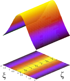
    Soliton's shape while propagating with N = 1, it does not change its shape
     
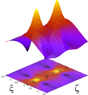
    Soliton's shape while propagating with N = 2, it changes its shape periodically

    For soliton solutions, N must be an integer and it is said to be the order or the soliton. For an exact closed form solution also exists; it has an even more complicated form, but the same periodicity occurs. In fact, all solitons with have the period . Their shape can easily be expressed only immediately after generation:

    on the right there is the plot of the second order soliton: at the beginning it has a shape of a sech, then the maximum amplitude increases and then comes back to the sech shape. Since high intensity is necessary to generate solitons, if the field increases its intensity even further the medium could be damaged.

    The condition to be solved if we want to generate a fundamental soliton is obtained expressing N in terms of all the known parameters and then putting :

    that, in terms of maximum irradiance value becomes:

    In most of the cases, the two variables that can be changed are the maximum intensity and the pulse width .

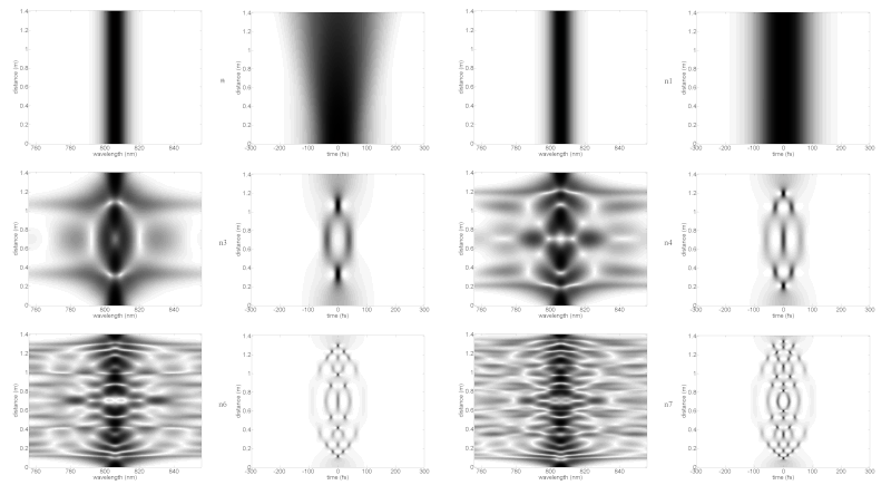
    Propagation of various higher-order optical solitons (image series: low power (no soliton), then n1–n7)

    Curiously, higher-order solitons can attain complicated shapes before returning exactly to their initial shape at the end of the soliton period. In the picture of various solitons, the spectrum (left) and time domain (right) are shown at varying distances of propagation (vertical axis) in an idealized nonlinear medium. This shows how a laser pulse might behave as it travels in a medium with the properties necessary to support fundamental solitons. In practice, in order to reach the very high peak intensity needed to achieve nonlinear effects, laser pulses may be coupled into optical fibers such as photonic-crystal fiber with highly confined propagating modes. Those fibers have more complicated dispersion and other characteristics which depart from the analytical soliton parameters.

    Generation of spatial solitons

    The first experiment on spatial optical solitons was reported in 1974 by Ashkin and Bjorkholm in a cell filled with sodium vapor. The field was then revisited in experiments at Limoges University in liquid carbon disulphide and expanded in the early '90s with the first observation of solitons in photorefractive crystals, glass, semiconductors and polymers. During the last decades numerous findings have been reported in various materials, for solitons of different dimensionality, shape, spiralling, colliding, fusing, splitting, in homogeneous media, periodic systems, and waveguides. Spatials solitons are also referred to as self-trapped optical beams and their formation is normally also accompanied by a self-written waveguide. In nematic liquid crystals, spatial solitons are also referred to as nematicons.

    Transverse-mode-locking solitons

    Localized excitations in lasers may appear due to synchronization of transverse modes.

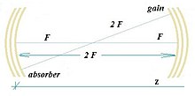
    Confocal laser cavity with nonlinear gain and absorber slices in Fourier-conjugated planes

    In confocal laser cavity the degenerate transverse modes with single longitudinal mode at wavelength mixed in nonlinear gain disc (located at ) and saturable absorber disc (located at ) of diameter are capable to produce spatial solitons of hyperbolic form:

    in Fourier-conjugated planes and .

    Temporal solitons

    The main problem that limits transmission bit rate in optical fibres is group velocity dispersion. It is because generated impulses have a non-zero bandwidth and the medium they are propagating through has a refractive index that depends on frequency (or wavelength). This effect is represented by the group delay dispersion parameter D; using it, it is possible to calculate exactly how much the pulse will widen:

    where L is the length of the fibre and is the bandwidth in terms of wavelength. The approach in modern communication systems is to balance such a dispersion with other fibers having D with different signs in different parts of the fibre: this way the pulses keep on broadening and shrinking while propagating. With temporal solitons it is possible to remove such a problem completely.

    Linear and nonlinear effects on Gaussian pulses

    Consider the picture on the right. On the left there is a standard Gaussian pulse, that's the envelope of the field oscillating at a defined frequency. We assume that the frequency remains perfectly constant during the pulse.

    Now we let this pulse propagate through a fibre with , it will be affected by group velocity dispersion. For this sign of D, the dispersion is anomalous, so that the higher frequency components will propagate a little bit faster than the lower frequencies, thus arriving before at the end of the fiber. The overall signal we get is a wider chirped pulse, shown in the upper right of the picture.

    effect of self-phase modulation on frequency

    Now let us assume we have a medium that shows only nonlinear Kerr effect but its refractive index does not depend on frequency: such a medium does not exist, but it's worth considering it to understand the different effects.

    The phase of the field is given by:

    the frequency (according to its definition) is given by:

    this situation is represented in the picture on the left. At the beginning of the pulse the frequency is lower, at the end it's higher. After the propagation through our ideal medium, we will get a chirped pulse with no broadening because we have neglected dispersion.

    Coming back to the first picture, we see that the two effects introduce a change in frequency in two different opposite directions. It is possible to make a pulse so that the two effects will balance each other. Considering higher frequencies, linear dispersion will tend to let them propagate faster, while nonlinear Kerr effect will slow them down. The overall effect will be that the pulse does not change while propagating: such pulses are called temporal solitons.

    History of temporal solitons

    In 1973, Akira Hasegawa and Fred Tappert of AT&T Bell Labs were the first to suggest that solitons could exist in optical fibres, due to a balance between self-phase modulation and anomalous dispersion. Also in 1973 Robin Bullough made the first mathematical report of the existence of optical solitons. He also proposed the idea of a soliton-based transmission system to increase performance of optical telecommunications.

    Solitons in a fibre optic system are described by the Manakov equations.

    In 1987, P. Emplit, J.P. Hamaide, F. Reynaud, C. Froehly and A. Barthelemy, from the Universities of Brussels and Limoges, made the first experimental observation of the propagation of a dark soliton, in an optical fiber.

    In 1988, Linn Mollenauer and his team transmitted soliton pulses over 4,000 kilometres using a phenomenon called the Raman effect, named for the Indian scientist Sir C. V. Raman who first described it in the 1920s, to provide optical gain in the fibre.

    In 1991, a Bell Labs research team transmitted solitons error-free at 2.5 gigabits over more than 14,000 kilometres, using erbium optical fibre amplifiers (spliced-in segments of optical fibre containing the rare earth element erbium). Pump lasers, coupled to the optical amplifiers, activate the erbium, which energizes the light pulses.

    In 1998, Thierry Georges and his team at France Télécom R&D Centre, combining optical solitons of different wavelengths (wavelength division multiplexing), demonstrated a data transmission of 1 terabit per second (1,000,000,000,000 units of information per second).

    In 2020, Optics Communications reported a Japanese team from MEXT, optical circuit switching with bandwidth of up to 90 Tbps (terabits per second), Optics Communications, Volume 466, 1 July 2020, 125677.

    Proof for temporal solitons

    An electric field is propagating in a medium showing optical Kerr effect through a guiding structure (such as an optical fibre) that limits the power on the xy plane. If the field is propagating towards z with a phase constant , then it can be expressed in the following form:

    where is the maximum amplitude of the field, is the envelope that shapes the impulse in the time domain; in general it depends on z because the impulse can change its shape while propagating; represents the shape of the field on the xy plane, and it does not change during propagation because we have assumed the field is guided. Both a and f are normalized dimensionless functions whose maximum value is 1, so that really represents the field amplitude.

    Since in the medium there is a dispersion we can not neglect, the relationship between the electric field and its polarization is given by a convolution integral. Anyway, using a representation in the Fourier domain, we can replace the convolution with a simple product, thus using standard relationships that are valid in simpler media. We Fourier-transform the electric field using the following definition:

    Using this definition, a derivative in the time domain corresponds to a product in the Fourier domain:

    the complete expression of the field in the frequency domain is:

    Now we can solve Helmholtz equation in the frequency domain:

    we decide to express the phase constant with the following notation:

    where we assume that (the sum of the linear dispersive component and the non-linear part) is a small perturbation, i.e. . The phase constant can have any complicated behaviour, but we can represent it with a Taylor series centred on :

    where, as known:

    we put the expression of the electric field in the equation and make some calculations. If we assume the slowly varying envelope approximation:

    we get:

    we are ignoring the behavior in the xy plane, because it is already known and given by . We make a small approximation, as we did for the spatial soliton:

    replacing this in the equation we get simply:

    .

    Now we want to come back in the time domain. Expressing the products by derivatives we get the duality:

    we can write the non-linear component in terms of the irradiance or amplitude of the field:

    for duality with the spatial soliton, we define:

    and this symbol has the same meaning of the previous case, even if the context is different. The equation becomes:

    We know that the impulse is propagating along the z axis with a group velocity given by , so we are not interested in it because we just want to know how the pulse changes its shape while propagating. We decide to study the impulse shape, i.e. the envelope function a(·) using a reference that is moving with the field at the same velocity. Thus we make the substitution

    and the equation becomes:

    We now further assume that the medium where the field is propagating in shows anomalous dispersion, i.e. or in terms of the group delay dispersion parameter . We make this more evident replacing in the equation . Let us define now the following parameters (the duality with the previous case is evident):

    replacing those in the equation we get:

    that is exactly the same equation we have obtained in the previous case. The first order soliton is given by:

    the same considerations we have made are valid in this case. The condition N = 1 becomes a condition on the amplitude of the electric field:

    or, in terms of irradiance:

    or we can express it in terms of power if we introduce an effective area defined so that :

    Stability of solitons

    We have described what optical solitons are and, using mathematics, we have seen that, if we want to create them, we have to create a field with a particular shape (just sech for the first order) with a particular power related to the duration of the impulse. But what if we are a bit wrong in creating such impulses? Adding small perturbations to the equations and solving them numerically, it is possible to show that mono-dimensional solitons are stable. They are often referred as (1 + 1) D solitons, meaning that they are limited in one dimension (x or t, as we have seen) and propagate in another one (z).

    If we create such a soliton using slightly wrong power or shape, then it will adjust itself until it reaches the standard sech shape with the right power. Unfortunately this is achieved at the expense of some power loss, that can cause problems because it can generate another non-soliton field propagating together with the field we want. Mono-dimensional solitons are very stable: for example, if we will generate a first order soliton anyway; if N is greater we'll generate a higher order soliton, but the focusing it does while propagating may cause high power peaks damaging the media.

    The only way to create a (1 + 1) D spatial soliton is to limit the field on the y axis using a dielectric slab, then limiting the field on x using the soliton.

    On the other hand, (2 + 1) D spatial solitons are unstable, so any small perturbation (due to noise, for example) can cause the soliton to diffract as a field in a linear medium or to collapse, thus damaging the material. It is possible to create stable (2 + 1) D spatial solitons using saturating nonlinear media, where the Kerr relationship is valid until it reaches a maximum value. Working close to this saturation level makes it possible to create a stable soliton in a three-dimensional space.

    If we consider the propagation of shorter (temporal) light pulses or over a longer distance, we need to consider higher-order corrections and therefore the pulse carrier envelope is governed by the higher-order nonlinear Schrödinger equation (HONSE) for which there are some specialized (analytical) soliton solutions.

    Effect of power losses

    As we have seen, in order to create a soliton it is necessary to have the right power when it is generated. If there are no losses in the medium, then we know that the soliton will keep on propagating forever without changing shape (1st order) or changing its shape periodically (higher orders). Unfortunately any medium introduces losses, so the actual behaviour of power will be in the form:

    this is a serious problem for temporal solitons propagating in fibers for several kilometers. Consider what happens for the temporal soliton, generalization to the spatial ones is immediate. We have proved that the relationship between power and impulse length is:

    if the power changes, the only thing that can change in the second part of the relationship is . if we add losses to the power and solve the relationship in terms of we get:

    the width of the impulse grows exponentially to balance the losses! this relationship is true as long as the soliton exists, i.e. until this perturbation is small, so it must be otherwise we can not use the equations for solitons and we have to study standard linear dispersion. If we want to create a transmission system using optical fibres and solitons, we have to add optical amplifiers in order to limit the loss of power.

    Generation of soliton pulse

    Experiments have been carried out to analyse the effect of high frequency (20 MHz-1 GHz) external magnetic field induced nonlinear Kerr effect on Single mode optical fibre of considerable length (50–100 m) to compensate group velocity dispersion (GVD) and subsequent evolution of soliton pulse ( peak energy, narrow, secant hyperbolic pulse). Generation of soliton pulse in fibre is an obvious conclusion as self phase modulation due to high energy of pulse offset GVD, whereas the evolution length is 2000 km. (the laser wavelength chosen greater than 1.3 micrometers). Moreover, peak soliton pulse is of period 1–3 ps so that it is safely accommodated in the optical bandwidth. Once soliton pulse is generated it is least dispersed over thousands of kilometres length of fibre limiting the number of repeater stations.

    Dark solitons

    In the analysis of both types of solitons we have assumed particular conditions about the medium:

    • in spatial solitons, , that means the self-phase modulation causes self-focusing
    • in temporal solitons, or , anomalous dispersion

    Is it possible to obtain solitons if those conditions are not verified? if we assume or , we get the following differential equation (it has the same form in both cases, we will use only the notation of the temporal soliton):

    This equation has soliton-like solutions. For the first order (N = 1):

    power of a dark soliton

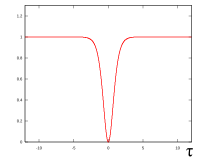
    The plot of is shown in the picture on the right. For higher order solitons () we can use the following closed form expression:

    It is a soliton, in the sense that it propagates without changing its shape, but it is not made by a normal pulse; rather, it is a lack of energy in a continuous time beam. The intensity is constant, but for a short time during which it jumps to zero and back again, thus generating a "dark pulse"'. Those solitons can actually be generated introducing short dark pulses in much longer standard pulses. Dark solitons are more difficult to handle than standard solitons, but they have shown to be more stable and robust to losses.

    Politics of Europe

    From Wikipedia, the free encyclopedia ...