From Wikipedia, the free encyclopedia
https://en.wikipedia.org/wiki/Blast_furnace
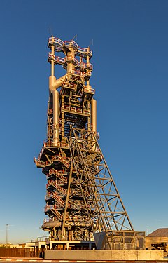
A blast furnace is a type of metallurgical furnace used for smelting to produce industrial metals, generally pig iron, but also others such as lead or copper. Blast refers to the combustion air being supplied above atmospheric pressure.
In a blast furnace, fuel (coke), ores, and flux (limestone) are continuously supplied through the top of the furnace, while a hot blast of air (sometimes with oxygen enrichment) is blown into the lower section of the furnace through a series of pipes called tuyeres, so that the chemical reactions take place throughout the furnace as the material falls downward. The end products are usually molten metal and slag phases tapped from the bottom, and waste gases (flue gas) exiting from the top of the furnace. The downward flow of the ore along with the flux in contact with an upflow of hot, carbon monoxide-rich combustion gases is a countercurrent exchange and chemical reaction process.
In contrast, air furnaces (such as reverberatory furnaces) are naturally aspirated, usually by the convection of hot gases in a chimney flue. According to this broad definition, bloomeries for iron, blowing houses for tin, and smelt mills for lead would be classified as blast furnaces. However, the term has usually been limited to those used for smelting iron ore to produce pig iron, an intermediate material used in the production of commercial iron and steel, and the shaft furnaces used in combination with sinter plants in base metals smelting.
Blast furnaces are estimated to have been responsible for over 4% of global greenhouse gas emissions between 1900 and 2015, but are difficult to decarbonize.
Process engineering and chemistry


Blast furnaces operate on the principle of chemical reduction whereby carbon monoxide converts iron oxides to elemental iron.
Blast furnaces differ from bloomeries and reverberatory furnaces in that in a blast furnace, flue gas is in direct contact with the ore and iron, allowing carbon monoxide to diffuse into the ore and reduce the iron oxide. The blast furnace operates as a countercurrent exchange process whereas a bloomery does not. Another difference is that bloomeries operate as a batch process whereas blast furnaces operate continuously for long periods. Continuous operation is also preferred because blast furnaces are difficult to start and stop. Also, the carbon in pig iron lowers the melting point below that of steel or pure iron; in contrast, iron does not melt in a bloomery.
Silica has to be removed from the pig iron. It reacts with calcium oxide (burned limestone) and forms silicates, which float to the surface of the molten pig iron as slag. Historically, to prevent contamination from sulfur, the best quality iron was produced with charcoal.
In a blast furnace, a downward-moving column of ore, flux, coke (or charcoal) and their reaction products must be sufficiently porous for the flue gas to pass through, upwards. To ensure this permeability the particle size of the coke or charcoal is of great relevance. Therefore, the coke must be strong enough so it will not be crushed by the weight of the material above it. Besides the physical strength of its particles, the coke must also be low in sulfur, phosphorus, and ash.
The main chemical reaction producing the molten iron is:
- Fe2O3 + 3CO → 2Fe + 3CO2
This reaction might be divided into multiple steps, with the first being that preheated air blown into the furnace reacts with the carbon in the form of coke to produce carbon monoxide and heat:
- 2 C(s) + O2(g) → 2 CO(g)
Hot carbon monoxide is the reducing agent for the iron ore and reacts with the iron oxide to produce molten iron and carbon dioxide. Depending on the temperature in the different parts of the furnace (warmest at the bottom) the iron is reduced in several steps. At the top, where the temperature usually is in the range between 200 °C and 700 °C, the iron oxide is partially reduced to iron(II,III) oxide, Fe3O4.
- 3 Fe2O3(s) + CO(g) → 2 Fe3O4(s) + CO2(g)
The temperatures 850 °C, further down in the furnace, the iron(II,III) is reduced further to iron(II) oxide:
- Fe3O4(s) + CO(g) → 3 FeO(s) + CO2(g)
Hot carbon dioxide, unreacted carbon monoxide, and nitrogen from the air pass up through the furnace as fresh feed material travels down into the reaction zone. As the material travels downward, the counter-current gases both preheat the feed charge and decompose the limestone to calcium oxide and carbon dioxide:
- CaCO3(s) → CaO(s) + CO2(g)
The calcium oxide formed by decomposition reacts with various acidic impurities in the iron (notably silica), to form a fayalitic slag which is essentially calcium silicate, CaSiO
3:
- SiO2 + CaO → CaSiO3
As the iron(II) oxide moves down to the area with higher temperatures, ranging up to 1200 °C degrees, it is reduced further to iron metal:
- FeO(s) + CO(g) → Fe(s) + CO2(g)
The carbon dioxide formed in this process is re-reduced to carbon monoxide by the coke:
- C(s) + CO2(g) → 2 CO(g)
The temperature-dependent equilibrium controlling the gas atmosphere in the furnace is called the Boudouard reaction:
- 2CO ⇌ CO2 + C
The pig iron produced by the blast furnace has a relatively high carbon content of around 4–5% and usually contains too much sulphur, making it very brittle, and of limited immediate commercial use. Some pig iron is used to make cast iron. The majority of pig iron produced by blast furnaces undergoes further processing to reduce the carbon and sulphur content and produce various grades of steel used for construction materials, automobiles, ships and machinery. Desulphurisation usually takes place during the transport of the liquid steel to the steelworks. This is done by adding calcium oxide, which reacts with the iron sulfide contained in the pig iron to form calcium sulfide (called lime desulfurization). In a further process step, the so-called basic oxygen steelmaking, the carbon is oxidized by blowing oxygen onto the liquid pig iron to form crude steel.
History


Cast iron has been found in China dating to the 5th century BC, but the earliest extant blast furnaces in China date to the 1st century AD and in the West from the High Middle Ages. They spread from the region around Namur in Wallonia (Belgium) in the late 15th century, being introduced to England in 1491. The fuel used in these was invariably charcoal. The successful substitution of coke for charcoal is widely attributed to English inventor Abraham Darby in 1709. The efficiency of the process was further enhanced by the practice of preheating the combustion air (hot blast), patented by Scottish inventor James Beaumont Neilson in 1828.
China
Archaeological evidence shows that bloomeries appeared in China around 800 BC. Originally it was thought that the Chinese started casting iron right from the beginning, but this theory has since been debunked by the discovery of 'more than ten' iron digging implements found in the tomb of Duke Jing of Qin (d. 537 BC), whose tomb is located in Fengxiang County, Shaanxi (a museum exists on the site today). There is however no evidence of the bloomery in China after the appearance of the blast furnace and cast iron. In China, blast furnaces produced cast iron, which was then either converted into finished implements in a cupola furnace, or turned into wrought iron in a fining hearth.
Although cast iron farm tools and weapons were widespread in China by the 5th century BC, employing workforces of over 200 men in iron smelters from the 3rd century onward, the earliest blast furnaces constructed were attributed to the Han dynasty in the 1st century AD. These early furnaces had clay walls and used phosphorus-containing minerals as a flux. Chinese blast furnaces ranged from around two to ten meters in height, depending on the region. The largest ones were found in modern Sichuan and Guangdong, while the 'dwarf" blast furnaces were found in Dabieshan. In construction, they are both around the same level of technological sophistication.
The effectiveness of the Chinese human and horse powered blast furnaces was enhanced during this period by the engineer Du Shi (c. AD 31), who applied the power of waterwheels to piston-bellows in forging cast iron. Early water-driven reciprocators for operating blast furnaces were built according to the structure of horse powered reciprocators that already existed. That is, the circular motion of the wheel, be it horse driven or water driven, was transferred by the combination of a belt drive, a crank-and-connecting-rod, other connecting rods, and various shafts, into the reciprocal motion necessary to operate a push bellow. Donald Wagner suggests that early blast furnace and cast iron production evolved from furnaces used to melt bronze. Certainly, though, iron was essential to military success by the time the State of Qin had unified China (221 BC). Usage of the blast and cupola furnace remained widespread during the Song and Tang dynasties. By the 11th century, the Song dynasty Chinese iron industry made a switch of resources from charcoal to coke in casting iron and steel, sparing thousands of acres of woodland from felling. This may have happened as early as the 4th century AD.
The primary advantage of the early blast furnace was in large scale production and making iron implements more readily available to peasants. Cast iron is more brittle than wrought iron or steel, which required additional fining and then cementation or co-fusion to produce, but for menial activities such as farming it sufficed. By using the blast furnace, it was possible to produce larger quantities of tools such as ploughshares more efficiently than the bloomery. In areas where quality was important, such as warfare, wrought iron and steel were preferred. Nearly all Han period weapons are made of wrought iron or steel, with the exception of axe-heads, of which many are made of cast iron.
Blast furnaces were also later used to produce gunpowder weapons such as cast iron bomb shells and cast iron cannons during the Song dynasty.
Medieval Europe
The simplest forge, known as the Corsican, was used prior to the advent of Christianity. Examples of improved bloomeries are the Stuckofen, sometimes called wolf-furnace, which remained until the beginning of the 19th century. Instead of using natural draught, air was pumped in by a trompe, resulting in better quality iron and an increased capacity. This pumping of air in with bellows is known as cold blast, and it increases the fuel efficiency of the bloomery and improves yield. They can also be built bigger than natural draught bloomeries.
Oldest European blast furnaces
The oldest known blast furnaces in the West were built in Durstel in Switzerland, the Märkische Sauerland in Germany, and at Lapphyttan in Sweden, where the complex was active between 1205 and 1300. At Noraskog in the Swedish parish of Järnboås, traces of even earlier blast furnaces have been found, possibly from around 1100. These early blast furnaces, like the Chinese examples, were very inefficient compared to those used today. The iron from the Lapphyttan complex was used to produce balls of wrought iron known as osmonds, and these were traded internationally – a possible reference occurs in a treaty with Novgorod from 1203 and several certain references in accounts of English customs from the 1250s and 1320s. Other furnaces of the 13th to 15th centuries have been identified in Westphalia.
The technology required for blast furnaces may have either been transferred from China, or may have been an indigenous innovation. Al-Qazvini in the 13th century and other travellers subsequently noted an iron industry in the Alburz Mountains to the south of the Caspian Sea. This is close to the silk route, so that the use of technology derived from China is conceivable. Much later descriptions record blast furnaces about three metres high.[34] As the Varangian Rus' people from Scandinavia traded with the Caspian (using their Volga trade route), it is possible that the technology reached Sweden by this means. The Vikings are known to have used double bellows, which greatly increases the volumetric flow of the blast.
The Caspian region may also have been the source for the design of the furnace at Ferriere, described by Filarete, involving a water-powered bellows at Semogo in Valdidentro in northern Italy in 1226. In a two-stage process the molten iron was tapped twice a day into water, thereby granulating it.
Cistercian contributions
The General Chapter of the Cistercian monks spread some technological advances across Europe. This may have included the blast furnace, as the Cistercians are known to have been skilled metallurgists. According to Jean Gimpel, their high level of industrial technology facilitated the diffusion of new techniques: "Every monastery had a model factory, often as large as the church and only several feet away, and waterpower drove the machinery of the various industries located on its floor." Iron ore deposits were often donated to the monks along with forges to extract the iron, and after a time surpluses were offered for sale. The Cistercians became the leading iron producers in Champagne, France, from the mid-13th century to the 17th century, also using the phosphate-rich slag from their furnaces as an agricultural fertilizer.
Archaeologists are still discovering the extent of Cistercian technology. At Laskill, an outstation of Rievaulx Abbey and the only medieval blast furnace so far identified in Britain, the slag produced was low in iron content. Slag from other furnaces of the time contained a substantial concentration of iron, whereas Laskill is believed to have produced cast iron quite efficiently. Its date is not yet clear, but it probably did not survive until Henry VIII's Dissolution of the Monasteries in the late 1530s, as an agreement (immediately after that) concerning the "smythes" with the Earl of Rutland in 1541 refers to blooms. Nevertheless, the means by which the blast furnace spread in medieval Europe has not finally been determined.
Origin and spread of early modern blast furnaces

Due to the increased demand for iron for casting cannons, the blast furnace came into widespread use in France in the mid 15th century.
The direct ancestor of those used in France and England was in the Namur region, in what is now Wallonia (Belgium). From there, they spread first to the Pays de Bray on the eastern boundary of Normandy and from there to the Weald of Sussex, where the first furnace (called Queenstock) in Buxted was built in about 1491, followed by one at Newbridge in Ashdown Forest in 1496. They remained few in number until about 1530 but many were built in the following decades in the Weald, where the iron industry perhaps reached its peak about 1590. Most of the pig iron from these furnaces was taken to finery forges for the production of bar iron.
The first British furnaces outside the Weald appeared during the 1550s, and many were built in the remainder of that century and the following ones. The output of the industry probably peaked about 1620, and was followed by a slow decline until the early 18th century. This was apparently because it was more economic to import iron from Sweden and elsewhere than to make it in some more remote British locations. Charcoal that was economically available to the industry was probably being consumed as fast as the wood to make it grew.
The first blast furnace in Russia opened in 1637 near Tula and was called the Gorodishche Works. The blast furnace spread from there to central Russia and then finally to the Urals.
Coke blast furnaces
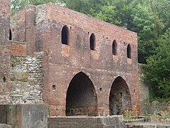


In 1709, at Coalbrookdale in Shropshire, England, Abraham Darby began to fuel a blast furnace with coke instead of charcoal. Coke's initial advantage was its lower cost, mainly because making coke required much less labor than cutting trees and making charcoal, but using coke also overcame localized shortages of wood, especially in Britain and on the Continent. Metallurgical grade coke will bear heavier weight than charcoal, allowing larger furnaces. A disadvantage is that coke contains more impurities than charcoal, with sulfur being especially detrimental to the iron's quality. Coke's impurities were more of a problem before hot blast reduced the amount of coke required and before furnace temperatures were hot enough to make slag from limestone free flowing. (Limestone ties up sulfur. Manganese may also be added to tie up sulfur.)
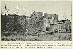
Coke iron was initially only used for foundry work, making pots and other cast iron goods. Foundry work was a minor branch of the industry, but Darby's son built a new furnace at nearby Horsehay, and began to supply the owners of finery forges with coke pig iron for the production of bar iron. Coke pig iron was by this time cheaper to produce than charcoal pig iron. The use of a coal-derived fuel in the iron industry was a key factor in the British Industrial Revolution. However, in many areas of the world charcoal was cheaper while coke was more expensive even after the Industrial Revolution: e. g., in the US charcoal-fueled iron production fell in share to about a half ca. 1850 but still continued to increase in absolute terms until ca. 1890, while in João Monlevade in the Brazilian Highlands charcoal-fired blast furnaces were built as late as the 1930s and only phased out in 2000.
Darby's original blast furnace has been archaeologically excavated and can be seen in situ at Coalbrookdale, part of the Ironbridge Gorge Museums. Cast iron from the furnace was used to make girders for the world's first cast iron bridge in 1779. The Iron Bridge crosses the River Severn at Coalbrookdale and remains in use for pedestrians.

Steam-powered blast
The steam engine was applied to power blast air, overcoming a shortage of water power in areas where coal and iron ore were located. This was first done at Coalbrookdale where a steam engine replaced a horse-powered pump in 1742. Such engines were used to pump water to a reservoir above the furnace. The first engines used to blow cylinders directly was supplied by Boulton and Watt to John Wilkinson's New Willey Furnace. This powered a cast iron blowing cylinder, which had been invented by his father Isaac Wilkinson. He patented such cylinders in 1736, to replace the leather bellows, which wore out quickly. Isaac was granted a second patent, also for blowing cylinders, in 1757. The steam engine and cast iron blowing cylinder led to a large increase in British iron production in the late 18th century.
Hot blast
Hot blast was the single most important advance in fuel efficiency of the blast furnace and was one of the most important technologies developed during the Industrial Revolution. Hot blast was patented by James Beaumont Neilson at Wilsontown Ironworks in Scotland in 1828. Within a few years of the introduction, hot blast was developed to the point where fuel consumption was cut by one-third using coke or two-thirds using coal, while furnace capacity was also significantly increased. Within a few decades, the practice was to have a "stove" as large as the furnace next to it into which the waste gas (containing CO) from the furnace was directed and burnt. The resultant heat was used to preheat the air blown into the furnace.
Hot blast enabled the use of raw anthracite coal, which was difficult to light, in the blast furnace. Anthracite was first tried successfully by George Crane at Ynyscedwyn Ironworks in south Wales in 1837. It was taken up in America by the Lehigh Crane Iron Company at Catasauqua, Pennsylvania, in 1839. Anthracite use declined when very high capacity blast furnaces requiring coke were built in the 1870s.
Modern applications of the blast furnace
Iron blast furnaces
The blast furnace remains an important part of modern iron production. Modern furnaces are highly efficient, including Cowper stoves to pre-heat the blast air and employ recovery systems to extract the heat from the hot gases exiting the furnace. Competition in industry drives higher production rates. The largest blast furnace in the world is in South Korea, with a volume around 6,000 m3 (210,000 cu ft). It can produce around 5,650,000 tonnes (5,560,000 LT) of iron per year.
This is a great increase from the typical 18th-century furnaces, which averaged about 360 tonnes (350 long tons; 400 short tons) per year. Variations of the blast furnace, such as the Swedish electric blast furnace, have been developed in countries which have no native coal resources.
According to Global Energy Monitor, the blast furnace is likely to become obsolete to meet climate change objectives of reducing carbon dioxide emission, but BHP disagrees. An alternative process involving direct reduced iron (DRI) is likely to succeed it, but this also needs to use a blast furnace to melt the iron and remove the gangue (impurities) unless the ore is very high quality.
Oxygen blast furnace
The oxygen blast furnace (OBF) process has been extensively studied theoretically because of the potentials of promising energy conservation and CO2 emission reduction. This type may be the most suitable for use with CCS. The main blast furnace has of three levels; the reduction zone (523–973 K (250–700 °C; 482–1,292 °F)), slag formation zone (1,073–1,273 K (800–1,000 °C; 1,472–1,832 °F)), and the combustion zone (1,773–1,873 K (1,500–1,600 °C; 2,732–2,912 °F)).
Blast furnaces are currently rarely used in copper smelting, but modern lead smelting blast furnaces are much shorter than iron blast furnaces and are rectangular in shape. Modern lead blast furnaces are constructed using water-cooled steel or copper jackets for the walls, and have no refractory linings in the side walls. The base of the furnace is a hearth of refractory material (bricks or castable refractory). Lead blast furnaces are often open-topped rather than having the charging bell used in iron blast furnaces.
The blast furnace used at the Nyrstar Port Pirie lead smelter differs from most other lead blast furnaces in that it has a double row of tuyeres rather than the single row normally used. The lower shaft of the furnace has a chair shape with the lower part of the shaft being narrower than the upper. The lower row of tuyeres being located in the narrow part of the shaft. This allows the upper part of the shaft to be wider than the standard.
Zinc blast furnaces
The blast furnaces used in the Imperial Smelting Process ("ISP") were developed from the standard lead blast furnace, but are fully sealed. This is because the zinc produced by these furnaces is recovered as metal from the vapor phase, and the presence of oxygen in the off-gas would result in the formation of zinc oxide.
Blast furnaces used in the ISP have a more intense operation than standard lead blast furnaces, with higher air blast rates per m2 of hearth area and a higher coke consumption.
Zinc production with the ISP is more expensive than with electrolytic zinc plants, so several smelters operating this technology have closed in recent years. However, ISP furnaces have the advantage of being able to treat zinc concentrates containing higher levels of lead than can electrolytic zinc plants.
Manufacture of stone wool

Stone wool or rock wool is a spun mineral fibre used as an insulation product and in hydroponics. It is manufactured in a blast furnace fed with diabase rock which contains very low levels of metal oxides. The resultant slag is drawn off and spun to form the rock wool product. Very small amounts of metals are also produced which are an unwanted by-product.
Modern iron process

- Iron ore + limestone sinter
- Coke
- Elevator
- Feedstock inlet
- Layer of coke
- Layer of sinter pellets of ore and limestone
- Hot blast (around 1200 °C)
- Removal of slag
- Tapping of molten pig iron
- Slag pot
- Torpedo car for pig iron
- Dust cyclone for separation of solid particles
- Cowper stoves for hot blast
- Smoke stack
- Feed air for Cowper stoves (air pre-heaters)
- Powdered coal
- Coke oven
- Coke
- Blast furnace gas downcomer
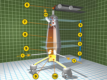
- Hot blast from Cowper stoves
- Melting zone (bosh)
- Reduction zone of ferrous oxide (barrel)
- Reduction zone of ferric oxide (stack)
- Pre-heating zone (throat)
- Feed of ore, limestone, and coke
- Exhaust gases
- Column of ore, coke and limestone
- Removal of slag
- Tapping of molten pig iron
- Collection of waste gases
Modern furnaces are equipped with an array of supporting facilities to increase efficiency, such as ore storage yards where barges are unloaded. The raw materials are transferred to the stockhouse complex by ore bridges, or rail hoppers and ore transfer cars. Rail-mounted scale cars or computer controlled weight hoppers weigh out the various raw materials to yield the desired hot metal and slag chemistry. The raw materials are brought to the top of the blast furnace via a skip car powered by winches or conveyor belts.
There are different ways in which the raw materials are charged into the blast furnace. Some blast furnaces use a "double bell" system where two "bells" are used to control the entry of raw material into the blast furnace. The purpose of the two bells is to minimize the loss of hot gases in the blast furnace. First, the raw materials are emptied into the upper or small bell which then opens to empty the charge into the large bell. The small bell then closes, to seal the blast furnace, while the large bell rotates to provide specific distribution of materials before dispensing the charge into the blast furnace. A more recent design is to use a "bell-less" system. These systems use multiple hoppers to contain each raw material, which is then discharged into the blast furnace through valves. These valves are more accurate at controlling how much of each constituent is added, as compared to the skip or conveyor system, thereby increasing the efficiency of the furnace. Some of these bell-less systems also implement a discharge chute in the throat of the furnace (as with the Paul Wurth top) in order to precisely control where the charge is placed.
The iron making blast furnace itself is built in the form of a tall structure, lined with refractory brick, and profiled to allow for expansion of the charged materials as they heat during their descent, and subsequent reduction in size as melting starts to occur. Coke, limestone flux, and iron ore (iron oxide) are charged into the top of the furnace in a precise filling order which helps control gas flow and the chemical reactions inside the furnace. Four "uptakes" allow the hot, dirty gas high in carbon monoxide content to exit the furnace throat, while "bleeder valves" protect the top of the furnace from sudden gas pressure surges. The coarse particles in the exhaust gas settle in the "dust catcher" and are dumped into a railroad car or truck for disposal, while the gas itself flows through a venturi scrubber and/or electrostatic precipitators and a gas cooler to reduce the temperature of the cleaned gas.
The "casthouse" at the bottom half of the furnace contains the bustle pipe, water cooled copper tuyeres and the equipment for casting the liquid iron and slag. Once a "taphole" is drilled through the refractory clay plug, liquid iron and slag flow down a trough through a "skimmer" opening, separating the iron and slag. Modern, larger blast furnaces may have as many as four tapholes and two casthouses. Once the pig iron and slag has been tapped, the taphole is again plugged with refractory clay.
The tuyeres are used to implement a hot blast, which is used to increase the efficiency of the blast furnace. The hot blast is directed into the furnace through water-cooled copper nozzles called tuyeres near the base. The hot blast temperature can be from 900 to 1,300 °C (1,650 to 2,370 °F) depending on the stove design and condition. The temperatures they deal with may be 2,000 to 2,300 °C (3,630 to 4,170 °F). Oil, tar, natural gas, powdered coal and oxygen can also be injected into the furnace at tuyere level to combine with the coke to release additional energy and increase the percentage of reducing gases present which is necessary to increase productivity.
The exhaust gasses of a blast furnace are generally cleaned in the dust collector – such as an inertial separator, a baghouse, or an electrostatic precipitator. Each type of dust collector has strengths and weaknesses – some collect fine particles, some coarse particles, some collect electrically charged particles. Effective exhaust clearing relies on multiple stages of treatment. Waste heat is usually collected from the exhaust gases, for example by the use of a Cowper stove, a variety of heat exchanger.
Environmental impact
Fossil fuel (coke, natural gas) use in blast furnaces is a source of greenhouse gas emissions and the blast furnace is the most emission intensive stage of the steel making process. Fuels and reductants such as plastic waste, biomass and hydrogen are being used by steelmakers as possible alternatives to fossil fuels, although cost and availability remain a challenge and deployment is limited.
Electric arc furnaces (EAF) are cited as an alternative steel production path which avoids the use of blast furnaces, however, depending on the characteristics of the steel product required the two furnace types are not always interchangeable. Furthermore, EAFs utilize steel scrap as a feedstock but estimates suggest that there will not be enough scrap available to meet future steel demand. Using hydrogen gas as a reductant to produce DRI (so called H2-DRI) from iron ore, which is then used as a feedstock for an EAF provides a technologically feasible, low emission alternative to blast furnaces. The H2-DRI EAF production route is in a fledgling state, with just one plant in operation.
A 2000 report from the International Energy Agency Greenhouse Gas Technical Collaboration Programme (IEAGHG) shows that 70% of the CO2 emissions from integrated steel plants arise directly from the blast furnace gas (BFG). By treating BFG with carbon capture technology prior to use for heat exchange and energy recovery within the plant, a portion of these emissions can be abated. The report estimates that chemical CO2 absorption would cost $35/t of CO2, plus $8–20/t CO2 for transportation and storage. At the time, this would have increased steel production costs by 15–20%, presenting a barrier to decarbonisation for steelmakers which typically operate with margins of 8-10%. As of 2024 no blast furnaces have been equipped with carbon capture technology.
ULCOS (Ultra Low CO2 Steelmaking) was a European programme exploring processes to reduce blast furnace emissions by at least 50%. Technologies identified include carbon capture and storage (CCS) and alternative energy sources and reductants such as hydrogen, electricity and biomass.

Preserved historic blast furnaces
Historically it was normal procedure for a decommissioned blast furnace to be demolished and either replaced with a newer, improved one, or to have the entire site demolished and treated for follow-up use of the area. In recent decades, several countries have realized the historic value of blast furnaces and have transformed them into museums. Examples can be found in the Czech Republic, France, Germany, Japan, Luxembourg, Poland, Romania, Mexico, Russia, Spain, United Kingdom, and United States.


