Search This Blog

Wednesday, May 27, 2020

High-level programming language

From Wikipedia, the free encyclopedia
 
In computer science, a high-level programming language is a programming language with strong abstraction from the details of the computer. In contrast to low-level programming languages, it may use natural language elements, be easier to use, or may automate (or even hide entirely) significant areas of computing systems (e.g. memory management), making the process of developing a program simpler and more understandable than when using a lower-level language. The amount of abstraction provided defines how "high-level" a programming language is.

In the 1960s, high-level programming languages using a compiler were commonly called autocodes. Examples of autocodes are COBOL and Fortran.

The first high-level programming language designed for computers was Plankalkül, created by Konrad Zuse. However, it was not implemented in his time, and his original contributions were largely isolated from other developments due to World War II, aside from the language's influence on the "Superplan" language by Heinz Rutishauser and also to some degree Algol. The first significantly widespread high-level language was Fortran, a machine-independent development of IBM's earlier Autocode systems. Algol, defined in 1958 and 1960 by committees of European and American computer scientists, introduced recursion as well as nested functions under lexical scope. It was also the first language with a clear distinction between value and name-parameters and their corresponding semantics. Algol also introduced several structured programming concepts, such as the while-do and if-then-else constructs and its syntax was the first to be described in formal notation – "Backus–Naur form" (BNF). During roughly the same period, Cobol introduced records (also called structs) and Lisp introduced a fully general lambda abstraction in a programming language for the first time.

Features

"High-level language" refers to the higher level of abstraction from machine language. Rather than dealing with registers, memory addresses and call stacks, high-level languages deal with variables, arrays, objects, complex arithmetic or boolean expressions, subroutines and functions, loops, threads, locks, and other abstract computer science concepts, with a focus on usability over optimal program efficiency. Unlike low-level assembly languages, high-level languages have few, if any, language elements that translate directly into a machine's native opcodes. Other features, such as string handling routines, object-oriented language features, and file input/output, may also be present. One thing to note about high-level programming languages is that these languages allow the programmer to be detached and separated from the machine. That is, unlike low-level languages like assembly or machine language, high-level programming can amplify the programmer's instructions and trigger a lot of data movements in the background without their knowledge. The responsibility and power of executing instructions have been handed over to the machine from the programmer.

Abstraction penalty

High-level languages intend to provide features which standardize common tasks, permit rich debugging, and maintain architectural agnosticism; while low-level languages often produce more efficient code through optimization for a specific system architecture. Abstraction penalty is the cost that high-level programming techniques pay for being unable to optimize performance or use certain hardware because they don't take advantage of certain low-level architectural resources. High-level programming exhibits features like more generic data structures and operations, run-time interpretation, and intermediate code files; which often result in execution of far more operations than necessary, higher memory consumption, and larger binary program size. For this reason, code which needs to run particularly quickly and efficiently may require the use of a lower-level language, even if a higher-level language would make the coding easier. In many cases, critical portions of a program mostly in a high-level language can be hand-coded in assembly language, leading to a much faster, more efficient, or simply reliably functioning optimised program.

However, with the growing complexity of modern microprocessor architectures, well-designed compilers for high-level languages frequently produce code comparable in efficiency to what most low-level programmers can produce by hand, and the higher abstraction may allow for more powerful techniques providing better overall results than their low-level counterparts in particular settings.[9] High-level languages are designed independent of a specific computing system architecture. This facilitates executing a program written in such a language on any computing system with compatible support for the Interpreted or JIT program. High-level languages can be improved as their designers develop improvements. In other cases, new high-level languages evolve from one or more others with the goal of aggregating the most popular constructs with new or improved features. An example of this is Scala which maintains backward compatibility with Java which means that programs and libraries written in Java will continue to be usable even if a programming shop switches to Scala; this makes the transition easier and the lifespan of such high-level coding indefinite. In contrast, low-level programs rarely survive beyond the system architecture which they were written for without major revision. This is the engineering 'trade-off' for the 'Abstraction Penalty'.

Relative meaning

Examples of high-level programming languages in active use today include Python, Visual Basic, Delphi, Perl, PHP, ECMAScript, Ruby, C#, Java and many others.

The terms high-level and low-level are inherently relative. Some decades ago, the C language, and similar languages, were most often considered "high-level", as it supported concepts such as expression evaluation, parameterised recursive functions, and data types and structures, while assembly language was considered "low-level". Today, many programmers might refer to C as low-level, as it lacks a large runtime-system (no garbage collection, etc.), basically supports only scalar operations, and provides direct memory addressing. It, therefore, readily blends with assembly language and the machine level of CPUs and microcontrollers.

Assembly language may itself be regarded as a higher level (but often still one-to-one if used without macros) representation of machine code, as it supports concepts such as constants and (limited) expressions, sometimes even variables, procedures, and data structures. Machine code, in its turn, is inherently at a slightly higher level than the microcode or micro-operations used internally in many processors.

Execution modes

There are three general modes of execution for modern high-level languages:
Interpreted
When code written in a language is interpreted, its syntax is read and then executed directly, with no compilation stage. A program called an interpreter reads each program statement, following the program flow, then decides what to do, and does it. A hybrid of an interpreter and a compiler will compile the statement into machine code and execute that; the machine code is then discarded, to be interpreted anew if the line is executed again. Interpreters are commonly the simplest implementations of the behavior of a language, compared to the other two variants listed here.
Compiled
When code written in a language is compiled, its syntax is transformed into an executable form before running. There are two types of compilation:
Machine code generation
Some compilers compile source code directly into machine code. This is the original mode of compilation, and languages that are directly and completely transformed to machine-native code in this way may be called truly compiled languages. See assembly language.
Intermediate representations
When code written in a language is compiled to an intermediate representation, that representation can be optimized or saved for later execution without the need to re-read the source file. When the intermediate representation is saved, it may be in a form such as bytecode. The intermediate representation must then be interpreted or further compiled to execute it. Virtual machines that execute bytecode directly or transform it further into machine code have blurred the once clear distinction between intermediate representations and truly compiled languages.
Source-to-source translated or transcompiled
Code written in a language may be translated into terms of a lower-level language for which native code compilers are already common. JavaScript and the language C are common targets for such translators. See CoffeeScript, Chicken Scheme, and Eiffel as examples. Specifically, the generated C and C++ code can be seen (as generated from the Eiffel language when using the EiffelStudio IDE) in the EIFGENs directory of any compiled Eiffel project. In Eiffel, the translated process is referred to as transcompiling or transcompiled, and the Eiffel compiler as a transcompiler or source-to-source compiler.
Note that languages are not strictly interpreted languages or compiled languages. Rather, implementations of language behavior use interpreting or compiling. For example, ALGOL 60 and Fortran have both been interpreted (even though they were more typically compiled). Similarly, Java shows the difficulty of trying to apply these labels to languages, rather than to implementations; Java is compiled to bytecode which is then executed by either interpreting (in a Java virtual machine (JVM)) or compiling (typically with a just-in-time compiler such as HotSpot, again in a JVM). Moreover, compiling, transcompiling, and interpreting are not strictly limited to only a description of the compiler artifact (binary executable or IL assembly).

High-level language computer architecture

Alternatively, it is possible for a high-level language to be directly implemented by a computer – the computer directly executes the HLL code. This is known as a high-level language computer architecture – the computer architecture itself is designed to be targeted by a specific high-level language. The Burroughs large systems were target machines for ALGOL 60, for example.

Software

From Wikipedia, the free encyclopedia

A diagram showing how the user interacts with application software on a typical desktop computer. The application software layer interfaces with the operating system, which in turn communicates with the hardware. The arrows indicate information flow.

Computer software, or simply software, is a collection of data or computer instructions that tell the computer how to work. This is in contrast to physical hardware, from which the system is built and actually performs the work. In computer science and software engineering, computer software is all information processed by computer systems, programs and data. Computer software includes computer programs, libraries and related non-executable data, such as online documentation or digital media. Computer hardware and software require each other and neither can be realistically used on its own.

At the lowest programming level, executable code consists of machine language instructions supported by an individual processor—typically a central processing unit (CPU) or a graphics processing unit (GPU). A machine language consists of groups of binary values signifying processor instructions that change the state of the computer from its preceding state. For example, an instruction may change the value stored in a particular storage location in the computer—an effect that is not directly observable to the user. An instruction may also invoke one of many input or output operations, for example displaying some text on a computer screen; causing state changes which should be visible to the user. The processor executes the instructions in the order they are provided, unless it is instructed to "jump" to a different instruction, or is interrupted by the operating system. As of 2015, most personal computers, smartphone devices and servers have processors with multiple execution units or multiple processors performing computation together, and computing has become a much more concurrent activity than in the past.

The majority of software is written in high-level programming languages. They are easier and more efficient for programmers because they are closer to natural languages than machine languages. High-level languages are translated into machine language using a compiler or an interpreter or a combination of the two. Software may also be written in a low-level assembly language, which has strong correspondence to the computer's machine language instructions and is translated into machine language using an assembler.

History

An outline (algorithm) for what would have been the first piece of software was written by Ada Lovelace in the 19th century, for the planned Analytical Engine. She created proofs to show how the engine would calculate Bernoulli Numbers. Because of the proofs and the algorithm, she is considered the first computer programmer.

The first theory about software—prior to the creation of computers as we know them today—was proposed by Alan Turing in his 1935 essay On Computable Numbers, with an Application to the Entscheidungsproblem (decision problem).

This eventually led to the creation of the academic fields of computer science and software engineering; Both fields study software and its creation. Computer science is the theoretical study of computer and software (Turing's essay is an example of computer science), whereas software engineering is the application of engineering and development of software.

However, prior to 1946, software was not yet the programs stored in the memory of stored-program digital computers, as we now understand it. The first electronic computing devices were instead rewired in order to "reprogram" them.

In 2000, Fred Shapiro, a librarian at the Yale Law School, published a letter revealing that John Wilder Tukey's 1958 paper "The Teaching of Concrete Mathematics" contained the earliest known usage of the term "software" found in a search of JSTOR's electronic archives, predating the OED's citation by two years. This led many to credit Tukey with coining the term, particularly in obituaries published that same year, although Tukey never claimed credit for any such coinage. In 1995, Paul Niquette claimed he had originally coined the term in October 1953, although he could not find any documents supporting his claim. The earliest known publication of the term "software" in an engineering context was in August 1953 by Richard R. Carhart, in a Rand Corporation Research Memorandum.

Types


On virtually all computer platforms, software can be grouped into a few broad categories.

Purpose, or domain of use

Based on the goal, computer software can be divided into:
  • Application software
    which is software that uses the computer system to perform special functions or provide entertainment functions beyond the basic operation of the computer itself. There are many different types of application software, because the range of tasks that can be performed with a modern computer is so large.
  • System software
    which is software for managing computer hardware behaviour, as to provide basic functionalities that are required by users, or for other software to run properly, if at all. System software is also designed for providing a platform for running application software, and it includes the following:
    • Operating systems
      which are essential collections of software that manage resources and provide common services for other software that runs "on top" of them. Supervisory programs, boot loaders, shells and window systems are core parts of operating systems. In practice, an operating system comes bundled with additional software (including application software) so that a user can potentially do some work with a computer that only has one operating system.
    • Device drivers
      which operate or control a particular type of device that is attached to a computer. Each device needs at least one corresponding device driver; because a computer typically has at minimum at least one input device and at least one output device, a computer typically needs more than one device driver.
    • Utilities
      which are computer programs designed to assist users in the maintenance and care of their computers.
  • Malicious software or malware
    which is software that is developed to harm and disrupt computers. As such, malware is undesirable. Malware is closely associated with computer-related crimes, though some malicious programs may have been designed as practical jokes.

Nature or domain of execution

  • Desktop applications such as web browsers and Microsoft Office, as well as smartphone and tablet applications (called "apps"). (There is a push in some parts of the software industry to merge desktop applications with mobile apps, to some extent. Windows 8, and later Ubuntu Touch, tried to allow the same style of application user interface to be used on desktops, laptops and mobiles.)
  •  
  • JavaScript scripts are pieces of software traditionally embedded in web pages that are run directly inside the web browser when a web page is loaded without the need for a web browser plugin. Software written in other programming languages can also be run within the web browser if the software is either translated into JavaScript, or if a web browser plugin that supports that language is installed; the most common example of the latter is ActionScript scripts, which are supported by the Adobe Flash plugin.
  • Server software, including:
  • Plugins and extensions are software that extends or modifies the functionality of another piece of software, and require that software be used in order to function;
  • Embedded software resides as firmware within embedded systems, devices dedicated to a single use or a few uses such as cars and televisions (although some embedded devices such as wireless chipsets can themselves be part of an ordinary, non-embedded computer system such as a PC or smartphone). In the embedded system context there is sometimes no clear distinction between the system software and the application software. However, some embedded systems run embedded operating systems, and these systems do retain the distinction between system software and application software (although typically there will only be one, fixed application which is always run).
  • Microcode is a special, relatively obscure type of embedded software which tells the processor itself how to execute machine code, so it is actually a lower level than machine code. It is typically proprietary to the processor manufacturer, and any necessary correctional microcode software updates are supplied by them to users (which is much cheaper than shipping replacement processor hardware). Thus an ordinary programmer would not expect to ever have to deal with it.

Programming tools

Programming tools are also software in the form of programs or applications that software developers (also known as programmers, coders, hackers or software engineers) use to create, debug, maintain (i.e. improve or fix), or otherwise support software.

Software is written in one or more programming languages; there are many programming languages in existence, and each has at least one implementation, each of which consists of its own set of programming tools. These tools may be relatively self-contained programs such as compilers, debuggers, interpreters, linkers, and text editors, that can be combined together to accomplish a task; or they may form an integrated development environment (IDE), which combines much or all of the functionality of such self-contained tools. IDEs may do this by either invoking the relevant individual tools or by re-implementing their functionality in a new way. An IDE can make it easier to do specific tasks, such as searching in files in a particular project. Many programming language implementations provide the option of using both individual tools or an IDE.

Topics

Architecture

Users often see things differently from programmers. People who use modern general purpose computers (as opposed to embedded systems, analog computers and supercomputers) usually see three layers of software performing a variety of tasks: platform, application, and user software.
  • Platform software
    The Platform includes the firmware, device drivers, an operating system, and typically a graphical user interface which, in total, allow a user to interact with the computer and its peripherals (associated equipment). Platform software often comes bundled with the computer. On a PC one will usually have the ability to change the platform software.
  • Application software
    Application software or Applications are what most people think of when they think of software. Typical examples include office suites and video games. Application software is often purchased separately from computer hardware. Sometimes applications are bundled with the computer, but that does not change the fact that they run as independent applications. Applications are usually independent programs from the operating system, though they are often tailored for specific platforms. Most users think of compilers, databases, and other "system software" as applications.
  • User-written software
    End-user development tailors systems to meet users' specific needs. User software includes spreadsheet templates and word processor templates. Even email filters are a kind of user software. Users create this software themselves and often overlook how important it is. Depending on how competently the user-written software has been integrated into default application packages, many users may not be aware of the distinction between the original packages, and what has been added by co-workers.

Execution

Computer software has to be "loaded" into the computer's storage (such as the hard drive or memory). Once the software has loaded, the computer is able to execute the software. This involves passing instructions from the application software, through the system software, to the hardware which ultimately receives the instruction as machine code. Each instruction causes the computer to carry out an operation—moving data, carrying out a computation, or altering the control flow of instructions.

Data movement is typically from one place in memory to another. Sometimes it involves moving data between memory and registers which enable high-speed data access in the CPU. Moving data, especially large amounts of it, can be costly. So, this is sometimes avoided by using "pointers" to data instead. Computations include simple operations such as incrementing the value of a variable data element. More complex computations may involve many operations and data elements together.

Quality and reliability

Software quality is very important, especially for commercial and system software like Microsoft Office, Microsoft Windows and Linux. If software is faulty (buggy), it can delete a person's work, crash the computer and do other unexpected things. Faults and errors are called "bugs" which are often discovered during alpha and beta testing. Software is often also a victim to what is known as software aging, the progressive performance degradation resulting from a combination of unseen bugs. 

Many bugs are discovered and eliminated (debugged) through software testing. However, software testing rarely—if ever—eliminates every bug; some programmers say that "every program has at least one more bug" (Lubarsky's Law). In the waterfall method of software development, separate testing teams are typically employed, but in newer approaches, collectively termed agile software development, developers often do all their own testing, and demonstrate the software to users/clients regularly to obtain feedback. Software can be tested through unit testing, regression testing and other methods, which are done manually, or most commonly, automatically, since the amount of code to be tested can be quite large. For instance, NASA has extremely rigorous software testing procedures for many operating systems and communication functions. Many NASA-based operations interact and identify each other through command programs. This enables many people who work at NASA to check and evaluate functional systems overall. Programs containing command software enable hardware engineering and system operations to function much easier together.

License

The software's license gives the user the right to use the software in the licensed environment, and in the case of free software licenses, also grants other rights such as the right to make copies. 

Proprietary software can be divided into two types:
  • freeware, which includes the category of "free trial" software or "freemium" software (in the past, the term shareware was often used for free trial/freemium software). As the name suggests, freeware can be used for free, although in the case of free trials or freemium software, this is sometimes only true for a limited period of time or with limited functionality.
  • software available for a fee, often inaccurately termed "commercial software", which can only be legally used on purchase of a license.
Open-source software, on the other hand, comes with a free software license, granting the recipient the rights to modify and redistribute the software.

Patents

Software patents, like other types of patents, are theoretically supposed to give an inventor an exclusive, time-limited license for a detailed idea (e.g. an algorithm) on how to implement a piece of software, or a component of a piece of software. Ideas for useful things that software could do, and user requirements, are not supposed to be patentable, and concrete implementations (i.e. the actual software packages implementing the patent) are not supposed to be patentable either—the latter are already covered by copyright, generally automatically. So software patents are supposed to cover the middle area, between requirements and concrete implementation. In some countries, a requirement for the claimed invention to have an effect on the physical world may also be part of the requirements for a software patent to be held valid—although since all useful software has effects on the physical world, this requirement may be open to debate. Meanwhile, American copyright law was applied to various aspects of the writing of the software code.

Software patents are controversial in the software industry with many people holding different views about them. One of the sources of controversy is that the aforementioned split between initial ideas and patent does not seem to be honored in practice by patent lawyers—for example the patent for Aspect-Oriented Programming (AOP), which purported to claim rights over any programming tool implementing the idea of AOP, howsoever implemented. Another source of controversy is the effect on innovation, with many distinguished experts and companies arguing that software is such a fast-moving field that software patents merely create vast additional litigation costs and risks, and actually retard innovation. In the case of debates about software patents outside the United States, the argument has been made that large American corporations and patent lawyers are likely to be the primary beneficiaries of allowing or continue to allow software patents.

Design and implementation

Design and implementation of software varies depending on the complexity of the software. For instance, the design and creation of Microsoft Word took much more time than designing and developing Microsoft Notepad because the latter has much more basic functionality.

Software is usually designed and created (aka coded/written/programmed) in integrated development environments (IDE) like Eclipse, IntelliJ and Microsoft Visual Studio that can simplify the process and compile the software (if applicable). As noted in a different section, software is usually created on top of existing software and the application programming interface (API) that the underlying software provides like GTK+, JavaBeans or Swing. Libraries (APIs) can be categorized by their purpose. For instance, the Spring Framework is used for implementing enterprise applications, the Windows Forms library is used for designing graphical user interface (GUI) applications like Microsoft Word, and Windows Communication Foundation is used for designing web services. When a program is designed, it relies upon the API. For instance, a Microsoft Windows desktop application might call API functions in the .NET Windows Forms library like Form1.Close() and Form1.Show() to close or open the application. Without these APIs, the programmer needs to write these functionalities entirely themselves. Companies like Oracle and Microsoft provide their own APIs so that many applications are written using their software libraries that usually have numerous APIs in them.

Data structures such as hash tables, arrays, and binary trees, and algorithms such as quicksort, can be useful for creating software. 

Computer software has special economic characteristics that make its design, creation, and distribution different from most other economic goods.

A person who creates software is called a programmer, software engineer or software developer, terms that all have a similar meaning. More informal terms for programmer also exist such as "coder" and "hacker" – although use of the latter word may cause confusion, because it is more often used to mean someone who illegally breaks into computer systems.

Industry and organizations

A great variety of software companies and programmers in the world comprise a software industry. Software can be quite a profitable industry: Bill Gates, the co-founder of Microsoft was the richest person in the world in 2009, largely due to his ownership of a significant number of shares in Microsoft, the company responsible for Microsoft Windows and Microsoft Office software products - both market leaders in their respective product categories.

Non-profit software organizations include the Free Software Foundation, GNU Project and the Mozilla Foundation. Software standard organizations like the W3C, IETF develop recommended software standards such as XML, HTTP and HTML, so that software can interoperate through these standards. 

Other well-known large software companies include Google, IBM, TCS, Infosys, Wipro, HCL Technologies, Oracle, Novell, SAP, Symantec, Adobe Systems, Sidetrade and Corel, while small companies often provide innovation.

STEP-NC

From Wikipedia, the free encyclopedia
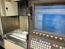
STEP-NC interface on a CNC, showing product shape and color-coded tolerance state

STEP-NC is a machine tool control language that extends the ISO 10303 STEP standards with the machining model in ISO 14649, adding geometric dimension and tolerance data for inspection, and the STEP PDM model for integration into the wider enterprise. The combined result has been standardized as ISO 10303-238 (also known as AP238). 

STEP-NC was designed to replace ISO 6983/RS274D G-codes with a modern, associative communications protocol that connects computer numerical controlled (CNC) process data to a product description of the part being machined.

A STEP-NC program can use the full range of geometric constructs from the STEP standard to communicate device-independent toolpaths to the CNC. It can provide CAM operational descriptions and STEP CAD geometry to the CNC so workpieces, stock, fixtures and cutting tool shapes can be visualized and analyzed in the context of the toolpaths. STEP GD&T information can also be added to enable quality measurement on the control, and CAM-independent volume removal features may be added to facilitate regeneration and modification of the toolpaths before or during machining for closed loop manufacturing.

Motivation

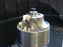
Impeller machined using STEP-NC

Input to a CNC in the ISO 6983/RS274D G-code control language is often machine-specific and limited to axis motion commands. The machine tool is given little or no information about the desired result of the machining.

STEP-NC allows more information about the machining process to be sent to the machine control and adds new information about the product being machined. This "Smart Data for Smart Machining" enables applications such as the following:
  • Toolpath descriptions that are portable and independent of machine geometry.
  • Visual process, to show toolpaths in context of the machine and workpiece, and eliminate drawings.
  • On-Machine Simulation, to check for gouges, machine interference and other undesired behavior.
  • Simplified Inspection, with linked tolerances, on-machine probes and inspection workplans tied to part tolerances.
  • Feed and Speed Optimization, using tolerances, cross section information, sensor data.
  • Associativity so feedback can be sent from manufacturing back to design.

Capabilities

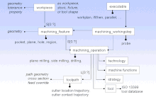
Overview of STEP-NC process model
STEP-NC can communicate a complete machining process description to a machine tool control or between manufacturing software applications. The information handled by STEP-NC can be divided into the following general categories. The standard handles technology-specific parameters for milling and turning, and extensions for other technologies under development (see Future Work). 

STEP-NC can exchange the explicit toolpath descriptions in use today, and add part, stock, and fixture geometry, a description of the tools, geometric dimensions and tolerances, and PDM information. A STEP-NC file is difficult to edit by hand because it contains geometry descriptions but for large programs the file size can be smaller because STEP-NC uses a compressed XML format instead of ASCII codes.

History

STEP-NC is not the first attempt at providing better quality information to a CNC. The EIA 494 Basic Control Language (BCL) defined a control language that was portable and had toolpaths independent of machine geometry, but did not contain any of the other product model information found in STEP-NC.

The core of STEP-NC is the ISO 14649 model for CNC control developed by European ESPRIT and IMS STEP-NC projects begun in 1999. These were led by Siemens with contributions from RWTH Aachen University and the University of Stuttgart in Germany, Komatsu and FANUC in Japan, Heidenhain in Switzerland, and the Pohang University of Science and Technology in Korea. Models for the control of CNC milling and turning machines were published in 2005, and draft models exist for EDM and contour cutting. 

Integration of the CNC model into STEP to produce ISO 10303-238 was done in the United States, under the NIST ATP Model Driven Intelligent Control of Manufacturing project, led by STEP Tools, Inc. with an industrial review board (IRB) consisting of Fortune 500 companies, CAD and CAM software developers, machine tool manufacturers, job shops and industry experts. STEP-NC AP238 was published in 2007.

STEP-NC Crown Wheel

In 2005 the OMAC STEP-NC Working Group hosted an AP238 testing forum in Orlando to demonstrate 5-axis parts machined using AP238 CC1 machine independent toolpaths. Four CAD/CAM systems produced AP238 machining programs for milling a 5-axis test part (an NAS 979 circle/diamond/square with an inverted NAS 979 cone test in the center). Each run on a pair of CNCs configured for completely different machine geometries (AB tool tilt vs. BC table tilt). In addition, Boeing cut parts on a variety of machines at their Tulsa facility and a machine at NIST in Gaithersburg.

In June 2006, a live 5-axis STEP-NC machining demonstration was hosted by Airbus at the Université Paul Sabatier Laboratoire de Génie mécanique in Toulouse. Further machining and measurement demonstrations were conducted in Ibusuki Japan in 2007.

On March 10–12, 2008, the STEP Manufacturing team (ISO TC184 SC4 WG3 T24) met in Sandviken and Stockholm, Sweden to demonstrate use of STEP-NC for feed and speed optimization, high-speed machining, tolerance-driven tool compensation and traceability. The participants in the demonstrations included Airbus/Univ. Bordeaux, Boeing, Eurostep, KTH Royal Institute of Technology, NIST, Sandvik Coromant, Scania, STEP Tools, and Univ. of Vigo.

On October 1–2, 2008, the STEP Manufacturing team met at the Connecticut Center for Advanced Technology, in Hartford, Connecticut to demonstrate closed-loop machining, feed optimization, and measurement using STEP-NC. The highlight of the meeting was the live 5-axis machining of a titanium impeller. Participants in the machining demonstration and other activities included Boeing, Connecticut Center for Advanced Technology, Concepts NRec, DMG, KTH Royal Institute of Technology, Mitutoyo, NIST, Sandvik Coromant, Scania, Siemens, and STEP Tools.

These participants and others continue to hold STEP-NC international implementation and testing events on a roughly six-month cycle. The demonstrations in 2009 focused on machining a Mold part at multiple sites from the same AP238 data including one part machined on a FANUC-developed STEP-NC control. At a meeting in Seattle the parts were then measured for accuracy using a CMM probe and a laser scanner.

STEP-NC machining on an Okuma CNC at IMTS 2014.

In the first half of 2010, the testing activity focused on tool wear management and machining a part in multiple setups with multiple alternate machining plans for 3, 4 and 5-axis machining. The new test part was a gear box that must be machined on all six sides. The tool wear and consequent machine loads were predicted from the STEP-NC data and verified using a dynamometer. In the second half of 2010, the testing forum applied STEP-NC to set up compensation with on-machine measurement of part and fixture datums using a FaroArm portable measurement device.

In 2012, the testing focused on machine tool accuracy calculations, culminating in a demonstration in June at the KTH production engineering labs in Stockholm. The test case milled a forged blank for a Crown Wheel Gear on an older Mazak VQC 20. Accuracy data from the machine was combined with tool engagement information from the STEP-NC to predict the deflections, which were tested against actual machining results.

In 2014, CAM data exchange using STEP-NC was shown at IMTS 2014 with daily machining demonstrations hosted by Okuma. A base machining process for a mold part was created by Boeing and then sent to Sandvik and ISCAR for optimization, producing a STEP-NC description containing all three process options. All machining was done in titanium and a range of CAM software was used, with all results captured as STEP-NC.

At IMTS 2018, a team consisting of Airbus, Boeing, DMG MORI, Hyundai WIA, Renishaw, and Mitutoyo demonstrated Digital Twin manufacturing by combining STEP-NC model and process data with MTConnect machine tool status and Quality Information Format (QIF) metrology results.

Future work

STEP-NC plasma cutting

Work continues within the ISO standard committees to extend STEP-NC to new technologies and to incorporate refinements discovered during use. Process models for new technologies are usually produced by the ISO TC184/SC1/WG7 committee. Models for Wire & Sink EDM and contour cutting of wood or stone are under investigation.

Work on extending and integrating STEP-NC with the manufacturing enterprise takes place in the ISO TC184/SC4/WG3/T24 STEP Manufacturing Team. This group also works on extensions and refinements discovered during testing. A series of traceability extensions have been proposed for linking STEP-NC machining programs with sensor feedback and machine state information during execution.

The National Shipbuilding Research Program (NSRP) has also hosted work to implement a prototype that connects a shipyard design system to a plate cutting using STEP-NC. This work involved extending STEP-NC to steel plate cutting and marking using lasers and plasma torches

A second edition of AP238 is being prepared for model-based integrated manufacturing, with geometry, tolerance, and kinematics improvements first introduced by AP242.

Computer-aided manufacturing

From Wikipedia, the free encyclopedia
 
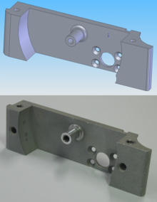
CAD model and CNC machined part

Computer-aided manufacturing (CAM) also known as Computer-aided Modeling or Computer-aided Machining is the use of software to control machine tools and related ones in the manufacturing of work pieces. This is not the only definition for CAM, but it is the most common; CAM may also refer to the use of a computer to assist in all operations of a manufacturing plant, including planning, management, transportation and storage. Its primary purpose is to create a faster production process and components and tooling with more precise dimensions and material consistency, which in some cases, uses only the required amount of raw material (thus minimizing waste), while simultaneously reducing energy consumption. CAM is now a system used in schools and lower educational purposes. CAM is a subsequent computer-aided process after computer-aided design (CAD) and sometimes computer-aided engineering (CAE), as the model generated in CAD and verified in CAE can be input into CAM software, which then controls the machine tool. CAM is used in many schools alongside Computer-Aided Design (CAD) to create objects.

Overview

Chrome-cobalt disc with crowns for dental implants, manufactured using WorkNC CAM

Traditionally, CAM has been considered a numerical control (NC) programming tool, wherein two-dimensional (2-D) or three-dimensional (3-D) models of components are generated in CAD. As with other “Computer-Aided” technologies, CAM does not eliminate the need for skilled professionals such as manufacturing engineers, NC programmers, or machinists. CAM leverages both the value of the most skilled manufacturing professionals through advanced productivity tools, while building the skills of new professionals through visualization, simulation and optimization tools.

History

Early commercial applications of CAM were in large companies in the automotive and aerospace industries; for example, Pierre Béziers work developing the CAD/CAM application UNISURF in the 1960s for car body design and tooling at Renault.

Historically, CAM software was seen to have several shortcomings that necessitated an overly high level of involvement by skilled CNC machinists. Fallows created the first CAD software but this had severe shortcomings and was promptly taken back into the developing stage. CAM software would output code for the least capable machine, as each machine tool control added on to the standard G-code set for increased flexibility. In some cases, such as improperly set up CAM software or specific tools, the CNC machine required manual editing before the program will run properly. None of these issues were so insurmountable that a thoughtful engineer or skilled machine operator could not overcome for prototyping or small production runs; G-Code is a simple language. In high production or high precision shops, a different set of problems were encountered where an experienced CNC machinist must both hand-code programs and run CAM software.

The integration of CAD with other components of CAD/CAM/CAE Product lifecycle management (PLM) environment requires an effective CAD data exchange. Usually it had been necessary to force the CAD operator to export the data in one of the common data formats, such as IGES or STL or Parasolid formats that are supported by a wide variety of software. The output from the CAM software is usually a simple text file of G-code/M-codes, sometimes many thousands of commands long, that is then transferred to a machine tool using a direct numerical control (DNC) program or in modern Controllers using a common USB Storage Device.

CAM packages could not, and still cannot, reason as a machinist can. They could not optimize toolpaths to the extent required of mass production. Users would select the type of tool, machining process and paths to be used. While an engineer may have a working knowledge of G-code programming, small optimization and wear issues compound over time. Mass-produced items that require machining are often initially created through casting or some other non-machine method. This enables hand-written, short, and highly optimized G-code that could not be produced in a CAM package. 

At least in the United States, there is a shortage of young, skilled machinists entering the workforce able to perform at the extremes of manufacturing; high precision and mass production. As CAM software and machines become more complicated, the skills required of a machinist or machine operator advance to approach that of a computer programmer and engineer rather than eliminating the CNC machinist from the workforce.

Typical areas of concern:
  • High-Speed Machining, including streamlining of tool paths
  • Multi-function Machining
  • 5 Axis Machining
  • Feature recognition and machining
  • Automation of Machining processes
  • Ease of Use

Overcoming historical shortcomings

Over time, the historical shortcomings of CAM are being attenuated, both by providers of niche solutions and by providers of high-end solutions. This is occurring primarily in three arenas:
  1. Ease of usage
  2. Manufacturing complexity
  3. Integration with PLM and the extended enterprise
Ease in use
For the user who is just getting started as a CAM user, out-of-the-box capabilities providing Process Wizards, templates, libraries, machine tool kits, automated feature based machining and job function specific tailorable user interfaces build user confidence and speed the learning curve.
User confidence is further built on 3D visualization through a closer integration with the 3D CAD environment, including error-avoiding simulations and optimizations.
Manufacturing complexity
The manufacturing environment is increasingly complex. The need for CAM and PLM tools by the manufacturing engineer, NC programmer or machinist is similar to the need for computer assistance by the pilot of modern aircraft systems. The modern machinery cannot be properly used without this assistance.
Today's CAM systems support the full range of machine tools including: turning, 5 axis machining, waterjet, laser / plasma cutting, and wire EDM. Today’s CAM user can easily generate streamlined tool paths, optimized tool axis tilt for higher feed rates, better tool life and surface finish, and ideal cutting depth. In addition to programming cutting operations, modern CAM softwares can additionally drive non-cutting operations such as machine tool probing.
Integration with PLM and the extended enterpriseLM to integrate manufacturing with enterprise operations from concept through field support of the finished product.
To ensure ease of use appropriate to user objectives, modern CAM solutions are scalable from a stand-alone CAM system to a fully integrated multi-CAD 3D solution-set. These solutions are created to meet the full needs of manufacturing personnel including part planning, shop documentation, resource management and data management and exchange. To prevent these solutions from detailed tool specific information a dedicated tool management

Machining process

Most machining progresses through many stages, each of which is implemented by a variety of basic and sophisticated strategies, depending on the part design, material, and software available.
Roughing
This process usually begins with raw stock, known as billet, or a rough casting which a CNC machine cuts roughly to shape of the final model, ignoring the fine details. In milling, the result often gives the appearance of terraces or steps, because the strategy has taken multiple "steps" down the part as it removes material. This takes the best advantage of the machine's ability by cutting material horizontally. Common strategies are zig-zag clearing, offset clearing, plunge roughing, rest-roughing, and trochoidal milling (adaptive clearing). The goal at this stage is to remove the most material in the least time, without much concern for overall dimensional accuracy. When roughing a part, a small amount of extra material is purposely left behind to be removed in subsequent finishing operation(s).
Semi-finishing
This process begins with a roughed part that unevenly approximates the model and cuts to within a fixed offset distance from the model. The semi-finishing pass must leave a small amount of material (called the scallop) so the tool can cut accurately, but not so little that the tool and material deflect away from the cutting surfaces. Common strategies are raster passes, waterline passes, constant step-over passes, pencil milling.
Finishing
Finishing involves many light passes across the material in fine steps to produce the finished part. When finishing a part, the steps between passes is minimal to prevent tool deflection and material spring back. In order to reduce the lateral tool load, tool engagement is reduced, while feed rates and spindle speeds are generally increased in order to maintain a target surface speed (SFM). A light chip load at high feed and RPM is often referred to as High Speed Machining (HSM), and can provide quick machining times with high quality results. The result of these lighter passes is a highly accurate part, with a uniformly high surface finish. In addition to modifying speeds and feeds, machinists will often have finishing specific endmills, which never used as roughing endmills. This is done to protect the endmill from developing chips and flaws in the cutting surface, which would leave streaks and blemishes on the final part.
Contour milling
In milling applications on hardware with four or more axes, a separate finishing process called contouring can be performed. Instead of stepping down in fine-grained increments to approximate a surface, the work piece is rotated to make the cutting surfaces of the tool tangent to the ideal part features. This produces an excellent surface finish with high dimensional accuracy. This process is commonly used to machine complex organic shapes such as turbine and impeller blades, which due to their complex curves and overlapping geometry, are impossible to machine with only three axis machines.

Significant other

From Wikipedia, the free encyclopedia https://en.wikipedia.org/wiki/Sig...