Search This Blog

Wednesday, January 29, 2020

Feathered dinosaur

From Wikipedia, the free encyclopedia
https://en.wikipedia.org/wiki/Feathered_dinosaur
 
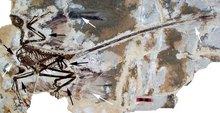
Fossil of Microraptor gui includes impressions of feathered wings (see arrows)

Since scientific research began on dinosaurs in the early 1800s, they were generally believed to be closely related to modern reptiles, such as lizards. The word "dinosaur" itself, coined in 1842 by paleontologist Richard Owen, comes from the Greek for "fearsome lizard". This view began to shift during the so-called dinosaur renaissance in scientific research in the late 1960s, and by the mid-1990s significant evidence had emerged that dinosaurs were much more closely related to birds, which descended directly from the theropod group of dinosaurs and are themselves a subgroup within the Dinosauria. 

Knowledge of the origin of feathers developed as new fossils were discovered throughout the 2000s and 2010s and as technology enabled scientists to study fossils more closely. Among non-avian dinosaurs, feathers or feather-like integument have been discovered in dozens of genera via direct and indirect fossil evidence. Although the vast majority of feather discoveries have been in coelurosaurian theropods, feather-like integument has also been discovered in at least three ornithischians, suggesting that feathers may have been present on the last common ancestor of the Ornithoscelida, a dinosaur group including both theropods and ornithischians. It is possible that feathers first developed in even earlier archosaurs, in light of the discovery of highly feather-like pycnofibers in pterosaurs. Crocodilians also possess beta keratin similar to those of birds, which suggests that they evolved from common ancestral genes.

History of research


 Early

The Berlin Archaeopteryx

Shortly after the 1859 publication of Charles Darwin's On the Origin of Species, British biologist Thomas Henry Huxley proposed that birds were descendants of dinosaurs. He compared the skeletal structure of Compsognathus, a small theropod dinosaur, and the 'first bird' Archaeopteryx lithographica (both of which were found in the Upper Jurassic Bavarian limestone of Solnhofen). He showed that, apart from its hands and feathers, Archaeopteryx was quite similar to Compsognathus. Thus Archaeopteryx represents a transitional fossil. In 1868 he published On the Animals which are most nearly intermediate between Birds and Reptiles, making the case. The first restoration of a feathered dinosaur was Thomas Henry Huxley's depiction in 1876 of a feathered Compsognathus to accompany a lecture on the evolution of birds he delivered in New York in which he speculated that the aforementioned dinosaur might have been in possession of feathers. The leading dinosaur expert of the time, Richard Owen, disagreed, claiming Archaeopteryx as the first bird outside dinosaur lineage. For the next century, claims that birds were dinosaur descendants faded, with more popular bird-ancestry hypotheses including 'crocodylomorph' and 'thecodont' ancestors, rather than dinosaurs or other archosaurs.

'Dinosaur renaissance'

In 1969, John Ostrom described Deinonychus antirrhopus, a theropod that he had discovered in Montana in 1964 and whose skeletal resemblance to birds seemed unmistakable. Ostrom became a leading proponent of the theory that birds are direct descendants of dinosaurs. Further comparisons of bird and dinosaur skeletons, as well as cladistic analysis strengthened the case for the link, particularly for a branch of theropods called maniraptors. Skeletal similarities include the neck, the pubis, the wrists (semi-lunate carpal), the 'arms' and pectoral girdle, the shoulder blade, the clavicle and the breast bone. In all, over a hundred distinct anatomical features are shared by birds and theropod dinosaurs. Other researchers drew on these shared features and other aspects of dinosaur biology and began to suggest that at least some theropod dinosaurs were feathered.

At the same time, paleoartists began to create modern restorations of highly active dinosaurs. In 1969, Robert T. Bakker drew a running Deinonychus. His student Gregory S. Paul depicted non-avian maniraptoran dinosaurs with feathers and protofeathers, starting in the late 1970s. In 1975, Eleanor M. Kish began to paint accurate images of dinosaurs, her Hypacrosaurus being the first one shown with its camouflage.

Before the discovery of feathered dinosaur fossils, the evidence was limited to Huxley and Ostrom's comparative anatomy. Some mainstream ornithologists, including Smithsonian Institution curator Storrs L. Olson, disputed the links, specifically citing the lack of fossil evidence for feathered dinosaurs. By the 1990s, however, most paleontologists considered birds to be surviving dinosaurs and referred to 'non-avian dinosaurs' (all extinct), to distinguish them from birds (Avialae).

Fossil discoveries

One of the earliest discoveries of possible feather impressions by non-avian dinosaurs is an ichnofossil (Fulicopus lyellii) of the 195-199 million year old Portland Formation in the northeastern United States. Gierlinski (1996, 1997, 1998) and Kondrat (2004) have interpreted traces between two footprints in this fossil as feather impressions from the belly of a squatting dilophosaurid. Although some reviewers have raised questions about the naming and interpretation of this fossil, if correct, this early Jurassic fossil is the oldest known evidence of feathers, almost 30 million years older than the next-oldest-known evidence.

Sinosauropteryx fossil, the first fossil of a definitively non-avialan dinosaur with feathers
 
After a century of hypotheses without conclusive evidence, well-preserved fossils of feathered dinosaurs were discovered during the 1990s, and more continue to be found. The fossils were preserved in a Lagerstätte—a sedimentary deposit exhibiting remarkable richness and completeness in its fossils—in Liaoning, China. The area had repeatedly been smothered in volcanic ash produced by eruptions in Inner Mongolia 124 million years ago, during the Early Cretaceous epoch. The fine-grained ash preserved the living organisms that it buried in fine detail. The area was teeming with life, with millions of leaves, angiosperms (the oldest known), insects, fish, frogs, salamanders, mammals, turtles, and lizards discovered to date.

The most important discoveries at Liaoning have been a host of feathered dinosaur fossils, with a steady stream of new finds filling in the picture of the dinosaur–bird connection and adding more to theories of the evolutionary development of feathers and flight. Turner et al. (2007) reported quill knobs from an ulna of Velociraptor mongoliensis, and these are strongly correlated with large and well-developed secondary feathers.

A nesting Citipati osmolskae specimen, at the AMNH
 
Behavioural evidence, in the form of an oviraptorosaur on its nest, showed another link with birds. Its forearms were folded, like those of a bird. Although no feathers were preserved, it is likely that these would have been present to insulate eggs and juveniles.

Not all of the Chinese fossil discoveries proved valid however. In 1999, a supposed fossil of an apparently feathered dinosaur named Archaeoraptor liaoningensis, found in Liaoning Province, northeastern China, turned out to be a forgery. Comparing the photograph of the specimen with another find, Chinese paleontologist Xu Xing came to the conclusion that it was composed of two portions of different fossil animals. His claim made National Geographic review their research and they too came to the same conclusion. The bottom portion of the "Archaeoraptor" composite came from a legitimate feathered dromaeosaurid now known as Microraptor, and the upper portion from a previously known primitive bird called Yanornis.

In 2011, samples of amber were discovered to contain preserved feathers from 75 to 80 million years ago during the Cretaceous era, with evidence that they were from both dinosaurs and birds. Initial analysis suggests that some of the feathers were used for insulation, and not flight. More complex feathers were revealed to have variations in coloration similar to modern birds, while simpler protofeathers were predominantly dark. Only 11 specimens are currently known. The specimens are too rare to be broken open to study their melanosomes, but there are plans for using non-destructive high-resolution X-ray imaging.

In 2016, the discovery was announced of a feathered dinosaur tail preserved in amber that is estimated to be 99 million years old. Lida Xing, a researcher from the China University of Geosciences in Beijing, found the specimen at an amber market in Myanmar. It is the first definitive discovery of dinosaur material in amber.

In March 2018, scientists reported that Archaeopteryx was likely capable of flight, but in a manner substantially different from that of modern birds.

Current knowledge


Non-avian dinosaur species preserved with evidence of feathers

Fossil of Sinornithosaurus millenii, the first evidence of feathers in dromaeosaurids
 
Cast of a Caudipteryx fossil with feather impressions and stomach content
 
Fossil cast of a Sinornithosaurus millenii
 
Several non-avian dinosaurs are now known to have been feathered. Direct evidence of feathers exists for several species. In all examples, the evidence described consists of feather impressions, except those genera inferred to have had feathers based on skeletal or chemical evidence, such as the presence of quill knobs (the anchor points for wing feathers on the forelimb) or a pygostyle (the fused vertebrae at the tail tip which often supports large feathers).

Primitive feather types

Integumentary structures that gave rise to the feathers of birds are seen in the dorsal spines of reptiles and fish. A similar stage in their evolution to the complex coats of birds and mammals can be observed in living reptiles such as iguanas and Gonocephalus agamids. Feather structures are thought to have proceeded from simple hollow filaments through several stages of increasing complexity, ending with the large, deeply rooted feathers with strong pens (rachis), barbs and barbules that birds display today.

According to Prum's (1999) proposed model, at stage I, the follicle originates with a cylindrical epidermal depression around the base of the feather papilla. The first feather resulted when undifferentiated tubular follicle collar developed out of the old keratinocytes being pushed out. At stage II, the inner, basilar layer of the follicle collar differentiated into longitudinal barb ridges with unbranched keratin filaments, while the thin peripheral layer of the collar became the deciduous sheath, forming a tuft of unbranched barbs with a basal calamus. Stage III consists of two developmental novelties, IIIa and IIIb, as either could have occurred first. Stage IIIa involves helical displacement of barb ridges arising within the collar. The barb ridges on the anterior midline of the follicle fuse together, forming the rachis. The creation of a posterior barb locus follows, giving an indeterminate number of barbs. This resulted in a feather with a symmetrical, primarily branched structure with a rachis and unbranched barbs. In stage IIIb, barbules paired within the peripheral barbule plates of the barb ridges, create branched barbs with rami and barbules. This resulting feather is one with a tuft of branched barbs without a rachis. At stage IV, differentiated distal and proximal barbules produce a closed, pennaceous vane. A closed vane develops when pennulae on the distal barbules form a hooked shape to attach to the simpler proximal barbules of the adjacent barb. Stage V developmental novelties gave rise to additional structural diversity in the closed pennaceous feather. Here, asymmetrical flight feathers, bipinnate plumulaceous feathers, filoplumes, powder down, and bristles evolved.

Some evidence suggests that the original function of simple feathers was insulation. In particular, preserved patches of skin in large, derived, tyrannosauroids show scutes, while those in smaller, more primitive, forms show feathers. This may indicate that the larger forms had complex skins, with both scutes and filaments, or that tyrannosauroids may be like rhinos and elephants, having filaments at birth and then losing them as they developed to maturity. An adult Tyrannosaurus rex weighed about as much as an African elephant. If large tyrannosauroids were endotherms, they would have needed to radiate heat efficiently. However, due to the different structural properties of feathers compared to fur, as well as a larger surface area per cubic square meter, it is extremely unlikely even the largest theropods would suffer overheating issues from an extensive feather coat.

There is an increasing body of evidence that supports the display hypothesis, which states that early feathers were colored and increased reproductive success. Coloration could have provided the original adaptation of feathers, implying that all later functions of feathers, such as thermoregulation and flight, were co-opted. This hypothesis has been supported by the discovery of pigmented feathers in multiple species. Supporting the display hypothesis is the fact that fossil feathers have been observed in a ground-dwelling herbivorous dinosaur clade, making it unlikely that feathers functioned as predatory tools or as a means of flight. Additionally, some specimens have iridescent feathers. Pigmented and iridescent feathers may have provided greater attractiveness to mates, providing enhanced reproductive success when compared to non-colored feathers. Current research shows that it is plausible that theropods would have had the visual acuity necessary to see the displays. In a study by Stevens (2006), the binocular field of view for Velociraptor has been estimated to be 55 to 60 degrees, which is about that of modern owls. Visual acuity for Tyrannosaurus has been predicted to be anywhere from about that of humans to 13 times that of humans. However, as both Velociraptor and Tyrannosaurus have a rather extended evolutionary relationship with the more basal theropods, it is unclear how much of this visual acuity data can be extrapolated.

The idea that precursors of feathers appeared before they were co-opted for insulation is already stated in Gould and Vrba, 1982. The original benefit might have been metabolic. Feathers are largely made of the keratin protein complex, which has disulfide bonds between amino acids that give it stability and elasticity. The metabolism of amino acids containing sulfur can be toxic; however, if the sulfur amino acids are not catabolized at the final products of urea or uric acid but used for the synthesis of keratin instead, the release of hydrogen sulfide is extremely reduced or avoided. For an organism whose metabolism works at high internal temperatures of 40 °C or greater, it can be extremely important to prevent the excess production of hydrogen sulfide. This hypothesis could be consistent with the need for high metabolic rate of theropod dinosaurs.

It is not known with certainty at what point in archosaur phylogeny the earliest simple "protofeathers" arose, or whether they arose once or independently multiple times. Filamentous structures are clearly present in pterosaurs, and long, hollow quills have been reported in specimens of the ornithischian dinosaurs Psittacosaurus and Tianyulong. In 2009, Xu et al. noted that the hollow, unbranched, stiff integumentary structures found on a specimen of Beipiaosaurus were strikingly similar to the integumentary structures of Psittacosaurus and pterosaurs. They suggested that all of these structures may have been inherited from a common ancestor much earlier in the evolution of archosaurs, possibly in an ornithodire from the Middle Triassic or earlier. More recently, findings in Russia of the basal neornithischian Kulindadromeus report that although the lower leg and tail seemed to be scaled, "varied integumentary structures were found directly associated with skeletal elements, supporting the hypothesis that simple filamentous feathers, as well as compound feather-like structures comparable to those in theropods, were widespread amongst the whole dinosaur clade."

Display feathers are also known from dinosaurs that are very primitive members of the bird lineage, or Avialae. The most primitive example is Epidexipteryx, which had a short tail with extremely long, ribbon-like feathers. Oddly enough, the fossil does not preserve wing feathers, suggesting that Epidexipteryx was either secondarily flightless, or that display feathers evolved before flight feathers in the bird lineage. Plumaceous feathers are found in nearly all lineages of Theropoda common in the northern hemisphere, and pennaceous feathers are attested as far down the tree as the Ornithomimosauria. The fact that only adult Ornithomimus had wing-like structures suggests that pennaceous feathers evolved for mating displays.

Phylogeny and the inference of feathers in other dinosaurs

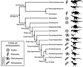
Cladogram showing distribution of feathers in Dinosauria, as of 2015
 
Fossil feather impressions are extremely rare and they require exceptional preservation conditions to form. Therefore, only a few non-avian feathered dinosaur genera have been identified. All fossil feather specimens have been found to show certain similarities. Due to these similarities and through developmental research, many scientists believe that feathers have only evolved once in dinosaurs. Feathers would then have been passed down to all later, more derived species, unless some lineages lost feathers secondarily. If a dinosaur falls at a point on an evolutionary tree within the known feather-bearing lineages, then its ancestors had feathers, and it is quite possible that it did as well. This technique, called phylogenetic bracketing, can also be used to infer the type of feathers a species may have had, since the developmental history of feathers is now reasonably well-known. All feathered species had filamentaceous or plumaceous (downy) feathers, with pennaceous feathers found among the more bird-like groups. The following cladogram is adapted from Godefroit et al., 2013.

Phylogenetic bracketing can also be used to evidence the lack of feathered integument by inference. For example, the presence of scaly integument in a specific clade would be a strong indicator that members in the clade would share similar integument, as independent evolution of feathers multiple times is unlikely, regardless if fossil evidence is present for all genera within the clade.

Grey denotes a clade that is not known to contain any feathered specimen at the time of writing, some of which have fossil evidence of scales. The presence or lack of feathered specimens in a given clade does not confirm that all members in a clade have the specified integument, unless corroborated with representative fossil evidence within clade members. 
 

Solar still

From Wikipedia, the free encyclopedia
https://en.wikipedia.org/wiki/Solar_still

Solar still built into a pit in the ground
 
"Watercone" solar still
 
Solar Seawater Still.svg

A solar still distills water with substances dissolved in it by using the heat of the Sun to evaporate water so that it may be cooled and collected, thereby purifying it. They are used in areas where drinking water is unavailable, so that clean water is obtained from dirty water or from plants by exposing them to sunlight.

There are many types of solar still, including large scale concentrated solar stills and condensation traps (better known as moisture traps amongst survivalists). In a solar still, impure water is contained outside the collector, where it is evaporated by sunlight shining through clear plastic or glass. The pure water vapour condenses on the cool inside surface and drips down, where it is collected and removed.

Distillation replicates the way nature makes rain. The sun's energy heats water to the point of evaporation. As the water evaporates, water vapour rises, condensing into water again as it cools and can then be collected. This process leaves behind impurities, such as salts and heavy metals, and eliminates microbiological organisms. The end result is pure distilled drinking water. 

History

Condensation traps have been in use since the pre-Incan peoples inhabited the Andes.

Today, a method for gathering water in moisture traps is still taught within the Argentinian Army for use by specialist units expected to conduct extended patrols of more than a week's duration in the arid border areas of the Andes.

Uses

Solar stills are used in cases where rain, piped, or well water is impractical, such as in remote homes or during power outages. In subtropical hurricane target areas that can lose power for days, solar distillation can provide an alternative source of clean water. 

Solar Well
 

Methods

Several methods of trapping condensation exist:

First method

This method was first used by the peoples of the Andes. A pit is dug into the earth, at the bottom of which is placed the receptacle that will be used to catch the condensed water. Small branches are placed with one of their ends inside the receptacle and their other ends up over the edge of the pit, forming a funnel to direct the condensed water into the receptacle. A lid is then built over this funnel, using more small branches, leaves, grasses, etc. The completed trap is left overnight, and moisture can be collected from the receptacle in the morning.

This method relies on the formation of dew or frost on the receptacle, funnel, and lid. Forming dew collects on and runs down the outside of the funnel and into the receptacle. This water would typically evaporate with the morning sun and thus vanish, but the lid traps the evaporating water and raises the humidity within the trap, reducing the amount of water that is lost. The shade produced by the lid also reduces the temperature within the trap, which further reduces the rate of water loss to evaporation.

Modern method

Today, with the advent of plastic sheeting, the moisture trap has become more efficient. 

The method is very similar to that described above, but a single sheet of plastic is used instead of branches and leaves. The greater efficiency of this type of trap arises from the waterproof nature of the plastic, which doesn't let any water vapour pass through it (some water vapour escapes through the leaves and branches of the first method). This efficiency requires a certain amount of diligence of the part of the user, in that the plastic sheet must be firmly attached to the ground on all sides; this is often accomplished by using stones to weight the sheet down and/or covering the edges of the plastic sheet with earth (such as that dug out to make the hole in which the trap sits). Weighting the centre of the plastic sheet down with a stone forms the funnel via which the condensed water will run into the receptacle.

Transpiration method

Water can be obtained by placing clear plastic bags over the leafy branch of a non-poisonous tree and tightly closing the bag's open end around the branch. Any holes in the bag must be sealed to prevent the loss of water vapour.

During photosynthesis plants lose water through a process called transpiration. A clear plastic bag sealed around a branch allows photosynthesis to continue, but traps the evaporating water causing the vapour pressure of water to rise to a point where it begins to condense on the surface of the plastic bag. Gravity then causes the water to run to the lowest part of the bag. Water is collected by tapping the bag and then resealing it. The leaves will continue to produce water as the roots draw it from the ground and photosynthesis occurs.

The vapour pressure of water in the sealed bag can rise so high that the leaves can no longer transpire, consequently when using this method, the water should be drained off every two hours and stored. Tests indicate that if this is not done the leaves stop producing water. 

If there are no large trees in the area, clumps of grass or small bushes can be placed inside the bag. If this is done the foliage will have to be replaced at regular intervals when water production is reduced, particularly if the foliage must be uprooted to place it in the bag.

Efficiency is greatest when the bag receives maximum sunshine at all times. Exposed roots are tested for water content. Soft, pulpy roots will yield the greatest amount of liquid for the least amount of effort.

Condensation trap efficiency

Condensation traps are not in themselves a sustainable source of water; they are sources for extending or supplementing existing water sources or supplies, and should not be relied on to provide a person's daily requirement for water, since a trap measuring 400 mm (16 in) in diameter by 300 mm (12 in) deep will only yield around 100 to 150 mL (3.4 to 5.1 US fl oz) per day. 

One method to increase the water output is to urinate into the pit before placing the receptacle in. This increases the moisture content of the earth, reducing the amount of water vapour that the earth can subsequently absorb. 

Materials

A simple basin-type solar still can be constructed with 2–4 stones, plastic film or transparent glass, a central weight to make a point and a container for the condensate. A cubic hole in moist ground is created of about 300 mm (12 in) on each side. Into the centre of this hole, a collection container is placed. Then a sheet of plastic film is stretched over the hole. Stills can also be made from water bottles or plastic bags.

Variations


Transpiration bag

An alternative method of the solar still is called the transpiration bag. The bag is a simple plastic bag and it folds over a stemmed plant with a corner pointing down to allow the condensate to pool. From there a person can remove the water by taking the bag off and pouring the water out or one can make a tiny incision into the corner to drip water into a cup. Its advantage over the basin type solar still mentioned before is that it only requires a bag like one can get at the grocery store. It doesn't need to be completely transparent. A disadvantage of the transpiration bag is the requirement for a plant in direct sunlight or heat to take the condensate.

In a study performed in 2009, variations to the angle of plastic and increasing the internal temperature of the hole versus the outside temperature made for better water production. Other methods used included using a brine to absorb water from and adding dyes to the brine to change the amount of solar radiation absorbed into the system. During the adjusted tilt angle experiment, the different angles used by the different researchers created different results and it was difficult for any of them to get a definite answer. In the graph, a bell curve is observed with the maximum water output being at 30 degrees angle adjustment. Each brine depth created a different amount of water and it is noted on the graph that about 25 millimetres (1 in) is optimal with a decreasing trend if more is used.

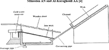
Wick still

This image shows how a wick basin solar still works.
 
The “wick” type solar still is a glass-topped box constructed and held at angle to allow sunlight in. Salt water poured in from the top is heated by sunlight, evaporating the water. It condenses on the underside of the glass and drips to the bottom. A pool of brine in the still is attached to the wicks which separates the water into banks to increase surface area for heating. The distilled water comes out of the bottom and, depending on the quality of construction, most of the salt has been purged from the water. The more wicks, the more heat can be transferred to the salt water and more product can be made. A plastic net can also catch salt water before it falls into the container and give it more time to heat up and separate into brine and water. The wick type solar still is made vapour-tight, as in the vapour does not escape to the atmosphere. To aid in absorbing more heat, some wicks are blackened to take in more heat. Glass's absorption of heat is negligible compared to plastic at higher temperatures. A problem, depending on application, with glass is that it is not flexible if the solar still is not a standard shape.

Practical considerations

The pit still may be inefficient as a survival still, requiring too much construction effort for the water produced. In desert environments water needs can exceed 3.8 litres (1 US gal) per day for a person at rest, while still production may average 240 millilitres (8 US fl oz) per day. Even with tools, digging a hole requires energy and makes a person lose water through perspiration; this means that even several days of water collection may not be equal to the water lost in its construction.

Seawater still

In 1952, the United States military developed a portable solar still for pilots stranded on the ocean, which comprises an inflatable 610-millimetre (24 in) plastic ball that floats on the ocean, with a flexible tube coming out the side. A separate plastic bag hangs from attachment points on the outer bag. Seawater is poured into the inner bag from an opening in the ball's neck. Fresh water is taken out by the pilot using the side tube that leads to bottom of the inflatable ball. It was stated in magazine articles that on a good day 2.4 litres (2.5 US qt) of fresh water could be produced. On an overcast day, 1.4 litres (1.5 US qt) was produced. Similar sea water stills are included in some life raft survival kits, though manual reverse osmosis desalinators have mostly replaced them.

Distilling urine

Using a condensation trap to distill urine will remove the urea and salt, providing one with drinkable water as a result.

Solar desalination

From Wikipedia, the free encyclopedia
https://en.wikipedia.org/wiki/Solar_desalination

Solar desalination is a technique to produce water with a low salt concentration from sea-water or brine using solar energy. There are two common methods of solar desalination. Either using the direct heat from the sun or using electricity generated by solar cells to power a membrane process.

Methods

In the direct method, a solar collector is coupled with a distilling mechanism and the process is carried out in one simple cycle. Solar stills of this type are described in survival guides, provided in marine survival kits, and employed in many small desalination and distillation plants. Water production by direct method solar distillation is proportional to the area of the solar surface and incidence angle and has an average estimated value of 3–4 litres per square metre (0.074–0.098 US gal/sq ft). Because of this proportionality and the relatively high cost of property and material for construction direct method distillation tends to favor plants with production capacities less than 200 m3/d (53,000 US gal/d).

Indirect solar desalination employs two separate systems; a solar collection array, consisting of photovoltaic and/or fluid based thermal collectors, and a separate conventional desalination plant.[2] Production by indirect method is dependent on the efficiency of the plant and the cost per unit produced is generally reduced by an increase in scale. Many different plant arrangements have been theoretically analyzed, experimentally tested and in some cases installed. They include but are not limited to multiple-effect humidification (MEH), multi-stage flash distillation (MSF), multiple-effect distillation (MED), multiple-effect boiling (MEB), humidification–dehumidification (HDH), reverse osmosis (RO), and freeze-effect distillation.

Indirect solar desalination systems using photovoltaic (PV) panels and reverse osmosis (RO) have been commercially available and in use since 2009. Output by 2013 is up to 1,600 litres (420 US gal) per hour per system, and 200 litres (53 US gal) per day per square metre of PV panel.[5][6] Municipal-scale systems are planned. Utirik Atoll in the Pacific Ocean has been supplied with fresh water this way since 2010.

Indirect solar desalination by a form of humidification/dehumidification is in use in the seawater greenhouse

History

Methods of solar distillation have been employed by humankind for thousands of years. From early Greek mariners to Persian alchemists, this basic technology has been utilized to produce both freshwater and medicinal distillates. Solar stills were in fact the first method used on a large scale to process contaminated water and convert it to a potable form.

In 1870 the first US patent was granted for a solar distillation device to Norman Wheeler and Walton Evans. Two years later in Las Salinas, Chile, Charles Wilson, a Swedish engineer, began building a direct method solar powered distillation plant to supply freshwater to workers at a saltpeter and silver mine. It operated continuously for 40 years and produced an average of 22.7 m3 of distilled water a day using the effluent from mining operations as its feed water.

Solar desalination of seawater and brackish groundwater in the modern United States extends back to the early 1950s when Congress passed the Conversion of Saline Water Act, which led to the establishment of the Office of Saline Water (OSW) in 1955. The OSW's main function was to administer funds for research and development of desalination projects. One of the five demonstration plants constructed was located in Daytona Beach, Florida and devoted to exploring methods of solar distillation. Many of the projects were aimed at solving water scarcity issues in remote desert and coastal communities. In the 1960s and 1970s several modern solar distillations plants were constructed on the Greek isles with capacities ranging from 2000 to 8500 m3/day.[3] In 1984 a MED plant was constructed in Abu-Dhabi with a capacity of 120 m3/day and is still in operation. In Italy, an open source design called "the Eliodomestico" by Gabriele Diamanti was developed for personal use at the building materials price of $50.

Of the estimated 22 million m3 of freshwater being produced a day through desalination processes worldwide, less than 1% is made using solar energy. The prevailing methods of desalination, MSF and RO, are energy intensive and rely heavily on fossil fuels. Because of inexpensive methods of freshwater delivery and abundant low cost energy resources, solar distillation has, up to this point, been viewed as cost prohibitive and impractical. It is estimated that desalination plants powered by conventional fuels consume the equivalent of 203 million tons of fuel a year. With the approach (or passage) of peak oil production, fossil fuel prices will continue to increase as those resources decline; as a result solar energy will become a more attractive alternative for achieving the world's desalination needs.

Types of solar desalination

There are two primary means of achieving desalination using solar energy, through a phase change by thermal input, or in a single phase through mechanical separation. Phase change (or multi-phase) can be accomplished by either direct or indirect solar distillation. Single phase desalination is predominantly accomplished in a solar-powered desalination unit, which uses photovoltaic cells that produce electricity to drive pumps, although there are experimental methods being researched using solar thermal collection to provide this mechanical energy.

Multi-stage flash distillation (MSF)

Multi-stage flash distillation is one of the predominant conventional phase-change methods of achieving desalination. It accounts for roughly 45% of the total world desalination capacity and 93% of all thermal methods.

Solar derivatives have been studied and in some cases implemented in small and medium scale plants around the world. In Margarita de Savoya, Italy there is a 50–60 m3/day MSF plant with a salinity gradient solar pond providing its thermal energy and storage capacity. In El Paso, Texas there is a similar project in operation that produces 19 m3/day. In Kuwait a MSF facility has been built using parabolic trough collectors to provide the necessary solar thermal energy to produce 100 m3 of fresh water a day. And in Northern China there is an experimental, automatic, unmanned operation that uses 80 m2 of vacuum tube solar collectors coupled with a 1 kW wind turbine (to drive several small pumps) to produce 0.8 m3/day.

Production data shows that MSF solar distillation has an output capacity of 6-60 L/m2/day versus the 3-4 L/m2/day standard output of a solar still. MSF experience very poor efficiency during start up or low energy periods. In order to achieve the highest efficiency MSF requires carefully controlled pressure drops across each stage and a steady energy input. As a result, solar applications require some form of thermal energy storage to deal with cloud interference, varying solar patterns, night time operation, and seasonal changes in ambient air temperature. As thermal energy storage capacity increases a more continuous process can be achieved and production rates approach maximum efficiency.

Problems with thermal systems

There are two inherent design problems facing any thermal solar desalination project. Firstly, the system's efficiency is governed by preferably high heat and mass transfer rates during evaporation and condensation. The surfaces have to be properly designed within the contradictory objectives of heat transfer efficiency, economy, and reliability.

Secondly, the heat of condensation is valuable because it takes large amounts of solar energy to evaporate water and generate saturated, vapor-laden hot air. This energy is, by definition, transferred to the condenser's surface during condensation. With most forms of solar stills, this heat of condensation is ejected from the system as waste heat. The challenge still existing in the field today, is to achieve the optimum temperature difference between the solar-generated vapor and the seawater-cooled condenser, maximal reuse of the energy of condensation, and minimizing the asset investment.

Solutions for thermal systems

Efficient desalination systems use heat recovery to allow the same heat input to provide several times the water than a simple evaporative process such as solar stills.

One solution to the barrier presented by the high level of solar energy required in solar desalination efforts is to reduce the pressure within the reservoir. This can be accomplished using a vacuum pump, and significantly decreases the temperature of heat energy required for desalination. For example, water at a pressure of 0.1 atmospheres boils at 50 °C (122 °F) rather than 100 °C (212 °F).

Solar humidification–dehumidification

The solar humidification–dehumidification (HDH) process (also called the multiple-effect humidification–dehumidification process, solar multistage condensation evaporation cycle (SMCEC) or multiple-effect humidification (MEH) is a technique that mimics the natural water cycle on a shorter time frame by evaporating and condensing water to separate it from other substances. The driving force in this process is thermal solar energy to produce water vapor which is later condensed in a separate chamber. In sophisticated systems, waste heat is minimized by collecting the heat from the condensing water vapor and pre-heating the incoming water source. This system is effective for small- to mid- scale desalination systems in remote locations because of the relative inexpensiveness of solar thermal collectors

Single-phase solar desalination

In indirect, or single phase, solar-powered desalination, two different technological systems are combined: a solar energy collection system (e.g. through the use of photovoltaic panels) and a proven desalination system such as reverse osmosis, are combined. Single phase solar desalination is predominantly accomplished by the use of photovoltaic cells that produce electricity to drive pumps used for reverse osmosis desalination. However, alternative experimental methods are being researched, which use solar thermal collection to provide mechanical energy to drive the reverse osmosis process. 

Solar-powered reverse osmosis

In reverse osmosis desalination systems, seawater pressure is raised above the natural osmotic pressure, forcing pure water through membrane pores to the fresh water side. Reverse osmosis (RO) is the most common desalination process in terms of installed capacity due to its superior energy efficiency compared to thermal desalination systems, despite requiring extensive water pre-treatment. Furthermore, part of the consumed mechanical energy can be reclaimed from the concentrated brine effluent with an energy recovery device.

Solar-powered RO desalination is common in demonstration plants due to the modularity and scalability of both photovoltaic (PV) and RO systems. A detailed economic analysis and a thorough optimisation strategy of PV powered RO desalination were carried out with favorable results reported. Economic and reliability considerations are the main challenges to improving PV powered RO desalination systems. However, the quickly dropping PV panel costs are making solar-powered desalination ever more feasible.

While the intermittent nature of sunlight and its variable intensity throughout the day makes PV efficiency prediction difficult and desalination during night time challenging, several solutions exist. For example, batteries, which provide the energy required for desalination in non-sunlight hours can be used to store solar energy in daytime. Apart from the use of conventional batteries, alternative methods for solar energy storage exist. For example, thermal energy storage systems solve this storage problem and ensure constant performance even during non-sunlight hours and cloudy days, improving overall efficiency.

Ion exchange

From Wikipedia, the free encyclopedia
https://en.wikipedia.org/wiki/Ion_exchange
 
Ion exchanger
 
Ion-exchange resin beads
 
Ion-exchange column used for protein purification

Ion exchange is an exchange of ions between two electrolytes or between an electrolyte solution and a complex. In most cases the term is used to denote the processes of purification, separation, and decontamination of aqueous and other ion-containing solutions with solid polymeric or mineralic "ion exchangers". 

Typical ion exchangers are ion-exchange resins (functionalized porous or gel polymer), zeolites, montmorillonite, clay, and soil humus. Ion exchangers are either cation exchangers, which exchange positively charged ions (cations), or anion exchangers, which exchange negatively charged ions (anions). There are also amphoteric exchangers that are able to exchange both cations and anions simultaneously. However, the simultaneous exchange of cations and anions can be more efficiently performed in mixed beds, which contain a mixture of anion- and cation-exchange resins, or passing the treated solution through several different ion-exchange materials.

Ion exchanges can be unselective or have binding preferences for certain ions or classes of ions, depending on their chemical structure. This can be dependent on the size of the ions, their charge, or their structure. Typical examples of ions that can bind to ion exchangers are:
Along with absorption and adsorption, ion exchange is a form of sorption.

Ion exchange is a reversible process, and the ion exchanger can be regenerated or loaded with desirable ions by washing with an excess of these ions.

Applications

Ion exchange is widely used in the food and beverage industry, hydrometallurgy, metals finishing, chemical, petrochemical, pharmaceutical technology, sugar and sweetener production, ground- and potable-water treatment, nuclear, softening, industrial water treatment, semiconductor, power, and many other industries.

A typical example of application is preparation of high-purity water for power engineering, electronic and nuclear industries; i.e. polymeric or mineralic insoluble ion exchangers are widely used for water softening, water purification, water decontamination, etc.

Ion exchange is a method widely used in household (laundry detergents and water filters) to produce soft water. This is accomplished by exchanging calcium Ca2+ and magnesium Mg2+ cations against Na+ or H+ cations (see water softening). Another application for ion exchange in domestic water treatment is the removal of nitrate and natural organic matter.

Industrial and analytical ion-exchange chromatography is another area to be mentioned. Ion-exchange chromatography is a chromatographical method that is widely used for chemical analysis and separation of ions. For example, in biochemistry it is widely used to separate charged molecules such as proteins. An important area of the application is extraction and purification of biologically produced substances such as proteins (amino acids) and DNA/RNA.

Ion-exchange processes are used to separate and purify metals, including separating uranium from plutonium and the other actinides, including thorium, neptunium, and americium. This process is also used to separate the lanthanides, such as lanthanum, cerium, neodymium, praseodymium, europium, and ytterbium, from each other. The separation of neodymium and praseodymium was a particularly difficult one, and those were formerly thought to be just one element didymium - but that is an alloy of the two.

There are two series of rare-earth metals, the lanthanides and the actinides, both of whose families all have very similar chemical and physical properties. Using methods developed by Frank Spedding in the 1940s, ion exchange processes were formerly the only practical way to separate them in large quantities, until the development of the "solvent extraction" techniques that can be scaled up enormously.

A very important case of ion-exchange is the PUREX process (Plutonium-URanium Extraction Process), which is used to separate the plutonium-239 and the uranium from americium, curium, neptunium, the radioactive fission products that come from nuclear reactors. Thus the waste products can be separated out for disposal. Next, the plutonium and uranium are available for making nuclear-energy materials, such as new reactor fuel.

The ion-exchange process is also used to separate other sets of very similar chemical elements, such as zirconium and hafnium, which is also very important for the nuclear industry. Physically, zirconium is practically transparent to free neutrons, used in building nuclear reactors, but hafnium is a very strong absorber of neutrons, used in reactor control rods. Thus, ion-exchange is used in nuclear reprocessing and the treatment of radioactive waste.

Ion-exchange resins in the form of thin membranes are also used in chloralkali process, fuel cells, and vanadium redox batteries.

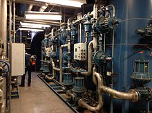
Large cation/anion ion exchangers used in water purification of boiler feedwater
 
Ion exchange can also be used to remove hardness from water by exchanging calcium and magnesium ions for sodium ions in an ion-exchange column. Liquid-phase (aqueous) ion-exchange desalination has been demonstrated. In this technique anions and cations in salt water are exchanged for carbonate anions and calcium cations respectively using electrophoresis. Calcium and carbonate ions then react to form calcium carbonate, which then precipitates, leaving behind fresh water. The desalination occurs at ambient temperature and pressure and requires no membranes or solid ion exchangers. The theoretical energy efficiency of this method is on par with electrodialysis and reverse osmosis.

Other applications


Regenerating wasted water

Most ion-exchange systems contain containers of ion-exchange resin that are operated on a cyclic basis. 

During the filtration process, water flows through the resin container until the resin is considered exhausted. That happened only when water leaving the exchanger contains more than the desired maximal concentration of the ions being removed. Resin is then regenerated by sequentially backwashing the resin bed to remove accumulated solids, flushing removed ions from the resin with a concentrated solution of replacement ions, and rinsing the flushing solution from the resin. Production of backwash, flushing, and rinsing wastewater during regeneration of ion-exchange media limits the usefulness of ion exchange for wastewater treatment.

Water softeners are usually regenerated with brine containing 10% sodium chloride. Aside from the soluble chloride salts of divalent cations removed from the softened water, softener regeneration wastewater contains the unused 50 – 70% of the sodium chloride regeneration flushing brine required to reverse ion-exchange resin equilibria. Deionizing resin regeneration with sulfuric acid and sodium hydroxide is approximately 20–40% efficient. Neutralized deionizer regeneration wastewater contains all of the removed ions plus 2.5–5 times their equivalent concentration as sodium sulfate.

Introduction to entropy

From Wikipedia, the free encyclopedia https://en.wikipedia.org/wiki/Introduct...