Search This Blog

Saturday, October 2, 2021

Gyroscope

From Wikipedia, the free encyclopedia

A gyroscope
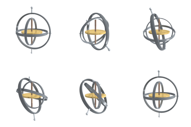
A gyroscope in operation. Note the freedom of rotation in all three axes. The rotor will maintain its spin axis direction regardless of the orientation of the outer frame.

A gyroscope (from Ancient Greek γῦρος gûros, "circle" and σκοπέω skopéō, "to look") is a device used for measuring or maintaining orientation and angular velocity. It is a spinning wheel or disc in which the axis of rotation (spin axis) is free to assume any orientation by itself. When rotating, the orientation of this axis is unaffected by tilting or rotation of the mounting, according to the conservation of angular momentum.

Gyroscopes based on other operating principles also exist, such as the microchip-packaged MEMS gyroscopes found in electronic devices (sometimes called gyrometers), solid-state ring lasers, fibre optic gyroscopes, and the extremely sensitive quantum gyroscope.

Applications of gyroscopes include inertial navigation systems, such as in the Hubble Telescope, or inside the steel hull of a submerged submarine. Due to their precision, gyroscopes are also used in gyrotheodolites to maintain direction in tunnel mining. Gyroscopes can be used to construct gyrocompasses, which complement or replace magnetic compasses (in ships, aircraft and spacecraft, vehicles in general), to assist in stability (bicycles, motorcycles, and ships) or be used as part of an inertial guidance system.

MEMS gyroscopes are popular in some consumer electronics, such as smartphones.

Description and diagram

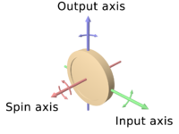
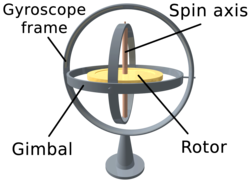
Diagram of a gyro wheel. Reaction arrows about the output axis (blue) correspond to forces applied about the input axis (green), and vice versa.

A gyroscope is an instrument, consisting of a wheel mounted into two or three gimbals providing pivoted supports, for allowing the wheel to rotate about a single axis. A set of three gimbals, one mounted on the other with orthogonal pivot axes, may be used to allow a wheel mounted on the innermost gimbal to have an orientation remaining independent of the orientation, in space, of its support.

In the case of a gyroscope with two gimbals, the outer gimbal, which is the gyroscope frame, is mounted so as to pivot about an axis in its own plane determined by the support. This outer gimbal possesses one degree of rotational freedom and its axis possesses none. The second gimbal, inner gimbal, is mounted in the gyroscope frame (outer gimbal) so as to pivot about an axis in its own plane that is always perpendicular to the pivotal axis of the gyroscope frame (outer gimbal). This inner gimbal has two degrees of rotational freedom.

The axle of the spinning wheel defines the spin axis. The rotor is constrained to spin about an axis, which is always perpendicular to the axis of the inner gimbal. So the rotor possesses three degrees of rotational freedom and its axis possesses two. The wheel responds to a force applied to the input axis by a reaction force to the output axis.

The behaviour of a gyroscope can be most easily appreciated by consideration of the front wheel of a bicycle. If the wheel is leaned away from the vertical so that the top of the wheel moves to the left, the forward rim of the wheel also turns to the left. In other words, rotation on one axis of the turning wheel produces rotation of the third axis.

A gyroscope flywheel will roll or resist about the output axis depending upon whether the output gimbals are of a free or fixed configuration. Examples of some free-output-gimbal devices would be the attitude reference gyroscopes used to sense or measure the pitch, roll and yaw attitude angles in a spacecraft or aircraft.

Animation of a gyro wheel in action

The centre of gravity of the rotor can be in a fixed position. The rotor simultaneously spins about one axis and is capable of oscillating about the two other axes, and it is free to turn in any direction about the fixed point (except for its inherent resistance caused by rotor spin). Some gyroscopes have mechanical equivalents substituted for one or more of the elements. For example, the spinning rotor may be suspended in a fluid, instead of being mounted in gimbals. A control moment gyroscope (CMG) is an example of a fixed-output-gimbal device that is used on spacecraft to hold or maintain a desired attitude angle or pointing direction using the gyroscopic resistance force.

In some special cases, the outer gimbal (or its equivalent) may be omitted so that the rotor has only two degrees of freedom. In other cases, the centre of gravity of the rotor may be offset from the axis of oscillation, and thus the centre of gravity of the rotor and the centre of suspension of the rotor may not coincide.

History

Gyroscope designed by Léon Foucault in 1852. Replica built by Dumoulin-Froment for the Exposition universelle in 1867. National Conservatory of Arts and Crafts museum, Paris.

Essentially, a gyroscope is a top combined with a pair of gimbals. Tops were invented in many different civilizations, including classical Greece, Rome, and China. Most of these were not utilized as instruments.

The first known apparatus similar to a gyroscope (the "Whirling Speculum" or "Serson's Speculum") was invented by John Serson in 1743. It was used as a level, to locate the horizon in foggy or misty conditions.

The first instrument used more like an actual gyroscope was made by Johann Bohnenberger of Germany, who first wrote about it in 1817. At first he called it the "Machine". Bohnenberger's machine was based on a rotating massive sphere. In 1832, American Walter R. Johnson developed a similar device that was based on a rotating disc. The French mathematician Pierre-Simon Laplace, working at the École Polytechnique in Paris, recommended the machine for use as a teaching aid, and thus it came to the attention of Léon Foucault. In 1852, Foucault used it in an experiment involving the rotation of the Earth. It was Foucault who gave the device its modern name, in an experiment to see (Greek skopeein, to see) the Earth's rotation (Greek gyros, circle or rotation), which was visible in the 8 to 10 minutes before friction slowed the spinning rotor.

In the 1860s, the advent of electric motors made it possible for a gyroscope to spin indefinitely; this led to the first prototype heading indicators, and a rather more complicated device, the gyrocompass. The first functional gyrocompass was patented in 1904 by German inventor Hermann Anschütz-Kaempfe. American Elmer Sperry followed with his own design later that year, and other nations soon realized the military importance of the invention—in an age in which naval prowess was the most significant measure of military power—and created their own gyroscope industries. The Sperry Gyroscope Company quickly expanded to provide aircraft and naval stabilizers as well, and other gyroscope developers followed suit.

In 1917, the Chandler Company of Indianapolis created the "Chandler gyroscope", a toy gyroscope with a pull string and pedestal. Chandler continued to produce the toy until the company was purchased by TEDCO inc. in 1982. The chandler toy is still produced by TEDCO today.

In the first several decades of the 20th century, other inventors attempted (unsuccessfully) to use gyroscopes as the basis for early black box navigational systems by creating a stable platform from which accurate acceleration measurements could be performed (in order to bypass the need for star sightings to calculate position). Similar principles were later employed in the development of inertial navigation systems for ballistic missiles.

During World War II, the gyroscope became the prime component for aircraft and anti-aircraft gun sights. After the war, the race to miniaturize gyroscopes for guided missiles and weapons navigation systems resulted in the development and manufacturing of so-called midget gyroscopes that weighed less than 3 ounces (85 g) and had a diameter of approximately 1 inch (2.5 cm). Some of these miniaturized gyroscopes could reach a speed of 24,000 revolutions per minute in less than 10 seconds.

Gyroscopes continue to be an engineering challenge. For example, the axle bearings have to be extremely accurate. A small amount of friction is deliberately introduced to the bearings, since otherwise an accuracy of better than of an inch (2.5 nm) would be required.

Three-axis MEMS-based gyroscopes are also being used in portable electronic devices such as tablets, smartphones, and smartwatches. This adds to the 3-axis acceleration sensing ability available on previous generations of devices. Together these sensors provide 6 component motion sensing; accelerometers for X,Y, and Z movement, and gyroscopes for measuring the extent and rate of rotation in space (roll, pitch and yaw). Some devices additionally incorporate a magnetometer to provide absolute angular measurements relative to the Earth's magnetic field. Newer MEMS-based inertial measurement units incorporate up to all nine axes of sensing in a single integrated circuit package, providing inexpensive and widely available motion sensing.

Gyroscopic principles

All spinning objects have gyroscopic properties. The main properties that an object can experience in any gyroscopic motion are rigidity in space and precession.

Rigidity in space

Rigidity in space describes the principle that a gyroscope remains in the fixed position on the plane in which it is spinning, unaffected by the Earth's rotation. For example, a bike wheel.

Precession

A simple case of precession, also known as steady precession, can be described by the following relation to Moment:

where represents precession, is represented by spin, is the nutation angle, and represents inertia along its respective axis. This relation is only valid with the Moment along the Y and Z axises are equal to 0.

The equation can be further reduced noting that the angular velocity along the z-axis is equal to the sum of the Precession and the Spin: , Where represents the angular velocity along the z axis.

or

Gyroscopic precession is torque induced. Described as the rate of change of the angular momentum and angular velocity that was produced by the same applied torque. This physical phenomenon results in the seemingly impossible dynamic occurrences. For example, a spinning top. This gyroscopic process is taken advantage of in many aerospace circumstances, such as airplanes and helicopters to help guide them into a desired orientation.

Contemporary uses

Steadicam

A Steadicam rig was employed during the filming of Return of the Jedi, in conjunction with two gyroscopes for extra stabilization, to film the background plates for the speeder bike chase. Steadicam inventor Garrett Brown operated the shot, walking through a redwood forest, running the camera at one frame per second. When projected at 24 frames per second, it gave the impression of flying through the air at perilous speeds.

Heading indicator

The heading indicator or directional gyro has an axis of rotation that is set horizontally, pointing north. Unlike a magnetic compass, it does not seek north. When being used in an airliner, for example, it will slowly drift away from north and will need to be reoriented periodically, using a magnetic compass as a reference.

Gyrocompass

Unlike a directional gyro or heading indicator, a gyrocompass seeks north. It detects the rotation of the Earth about its axis and seeks the true north, rather than the magnetic north. Gyrocompasses usually have built-in damping to prevent overshoot when re-calibrating from sudden movement.

Accelerometer

By determining an object's acceleration and integrating over time, the velocity of the object can be calculated. Integrating again, position can be determined. The simplest accelerometer is a weight that is free to move horizontally, which is attached to a spring and a device to measure the tension in the spring. This can be improved by introducing a counteracting force to push the weight back and to measure the force needed to prevent the weight from moving. A more complicated design consists of a gyroscope with a weight on one of the axes. The device will react to the force generated by the weight when it is accelerated, by integrating that force to produce a velocity.

Variations

Gyrostat

A gyrostat consists of a massive flywheel concealed in a solid casing. Its behaviour on a table, or with various modes of suspension or support, serves to illustrate the curious reversal of the ordinary laws of static equilibrium due to the gyrostatic behaviour of the interior invisible flywheel when rotated rapidly. The first gyrostat was designed by Lord Kelvin to illustrate the more complicated state of motion of a spinning body when free to wander about on a horizontal plane, like a top spun on the pavement, or a bicycle on the road. Kelvin also made use of gyrostats to develop mechanical theories of the elasticity of matter and of the ether. In modern continuum mechanics there is a variety of these models, based on ideas of Lord Kelvin. They represent a specific type of Cosserat theories (suggested for the first time by Eugène Cosserat and François Cosserat), which can be used for description of artificially made smart materials as well as of other complex media. One of them, so-called Kelvin's medium, has the same equations as magnetic insulators near the state of magnetic saturation in the approximation of quasimagnetostatics.

In modern times, the gyrostat concept is used in the design of attitude control systems for orbiting spacecraft and satellites. For instance, the Mir space station had three pairs of internally mounted flywheels known as gyrodynes or control moment gyros.

In physics, there are several systems whose dynamical equations resemble the equations of motion of a gyrostat. Examples include a solid body with a cavity filled with an inviscid, incompressible, homogeneous liquid, the static equilibrium configuration of a stressed elastic rod in elastica theory, the polarization dynamics of a light pulse propagating through a nonlinear medium, the Lorenz system in chaos theory, and the motion of an ion in a Penning trap mass spectrometer.

MEMS gyroscope

A microelectromechanical systems (MEMS) gyroscope is a miniaturized gyroscope found in electronic devices. It takes the idea of the Foucault pendulum and uses a vibrating element. This kind of gyroscope was first used in military applications but has since been adopted for increasing commercial use.

HRG

The hemispherical resonator gyroscope (HRG), also called a wine-glass gyroscope or mushroom gyro, makes use of a thin solid-state hemispherical shell, anchored by a thick stem. This shell is driven to a flexural resonance by electrostatic forces generated by electrodes which are deposited directly onto separate fused-quartz structures that surround the shell. Gyroscopic effect is obtained from the inertial property of the flexural standing waves.

VSG or CVG

A vibrating structure gyroscope (VSG), also called a Coriolis vibratory gyroscope (CVG), uses a resonator made of different metallic alloys. It takes a position between the low-accuracy, low-cost MEMS gyroscope and the higher-accuracy and higher-cost fiber optic gyroscope. Accuracy parameters are increased by using low-intrinsic damping materials, resonator vacuumization, and digital electronics to reduce temperature dependent drift and instability of control signals.

High quality wine-glass resonators are used for precise sensors like HRG.

DTG

A dynamically tuned gyroscope (DTG) is a rotor suspended by a universal joint with flexure pivots. The flexure spring stiffness is independent of spin rate. However, the dynamic inertia (from the gyroscopic reaction effect) from the gimbal provides negative spring stiffness proportional to the square of the spin speed (Howe and Savet, 1964; Lawrence, 1998). Therefore, at a particular speed, called the tuning speed, the two moments cancel each other, freeing the rotor from torque, a necessary condition for an ideal gyroscope.

Ring laser gyroscope

A ring laser gyroscope relies on the Sagnac effect to measure rotation by measuring the shifting interference pattern of a beam split into two-halves, as the two-halves move around the ring in opposite directions.

When the Boeing 757-200 entered service in 1983, it was equipped with the first suitable ring laser gyroscope. This gyroscope took many years to develop, and the experimental models went through many changes before it was deemed ready for production by the engineers and managers of Honeywell and Boeing. It was an outcome of the competition with mechanical gyroscopes, which kept improving. The reason Honeywell, of all companies, chose to develop the laser gyro was that they were the only one that didn't have a successful line of mechanical gyroscopes, so they wouldn't be competing against themselves. The first problem they had to solve was that with laser gyros rotations below a certain minimum could not be detected at all, due to a problem called "lock-in", whereby the two beams act like coupled oscillators and pull each other's frequencies toward convergence and therefore zero output. The solution was to shake the gyro rapidly so that it never settled into lock-in. Paradoxically, too regular of a dithering motion produced an accumulation of short periods of lock-in when the device was at rest at the extremities of its shaking motion. This was cured by applying a random white noise to the vibration. The material of the block was also changed from quartz to a new glass ceramic Cer-Vit, made by Owens Corning, because of helium leaks.

Fiber optic gyroscope

A fiber optic gyroscope also uses the interference of light to detect mechanical rotation. The two-halves of the split beam travel in opposite directions in a coil of fiber optic cable as long as 5 km. Like the ring laser gyroscope, it makes use of the Sagnac effect.

London moment

A London moment gyroscope relies on the quantum-mechanical phenomenon, whereby a spinning superconductor generates a magnetic field whose axis lines up exactly with the spin axis of the gyroscopic rotor. A magnetometer determines the orientation of the generated field, which is interpolated to determine the axis of rotation. Gyroscopes of this type can be extremely accurate and stable. For example, those used in the Gravity Probe B experiment measured changes in gyroscope spin axis orientation to better than 0.5 milliarcseconds (1.4×10⁻⁷ degrees, or about 2.4×10⁻⁹ radians) over a one-year period. This is equivalent to an angular separation the width of a human hair viewed from 32 kilometers (20 mi) away.

The GP-B gyro consists of a nearly-perfect spherical rotating mass made of fused quartz, which provides a dielectric support for a thin layer of niobium superconducting material. To eliminate friction found in conventional bearings, the rotor assembly is centered by the electric field from six electrodes. After the initial spin-up by a jet of helium which brings the rotor to 4,000 RPM, the polished gyroscope housing is evacuated to an ultra-high vacuum to further reduce drag on the rotor. Provided the suspension electronics remain powered, the extreme rotational symmetry, lack of friction, and low drag will allow the angular momentum of the rotor to keep it spinning for about 15,000 years.

A sensitive DC SQUID that can discriminate changes as small as one quantum, or about 2 ×10⁻¹⁵ Wb, is used to monitor the gyroscope. A precession, or tilt, in the orientation of the rotor causes the London moment magnetic field to shift relative to the housing. The moving field passes through a superconducting pickup loop fixed to the housing, inducing a small electric current. The current produces a voltage across a shunt resistance, which is resolved to spherical coordinates by a microprocessor. The system is designed to minimize Lorentz torque on the rotor.

Other examples

Helicopters

The main rotor of a helicopter acts like a gyroscope. Its motion is influenced by the principle of gyroscopic precession which is the concept that a force applied to a spinning object will have a maximum reaction approximately 90 degrees later. The reaction may differ from 90 degrees when other stronger forces are in play. To change direction, helicopters must adjust the pitch angle and the angle of attack.

Gyro X

A prototype vehicle created by Alex Tremulis and Thomas Summers in 1967. The car utilizes gyroscopic precession to drive on two wheels. An assembly consisting of a flywheel mounted in a gimbal housing under the hood of the vehicle acted as a large gyroscope. The flywheel was rotated by hydraulic pumps creating a gyroscopic effect on the vehicle. A precessional ram was responsible for rotating the gyroscope to change the direction of the precessional force to counteract any forces causing the vehicle imbalance. The one-of-a-kind prototype is now at the Lane Motor Museum in Nashville, Tennessee.

Consumer electronics

A digital gyroscope module connected to an Arduino Uno board
 

In addition to being used in compasses, aircraft, computer pointing devices, etc., gyroscopes have been introduced into consumer electronics. The first usage or application of the gyroscope in consumer electronics was popularized by Steve Jobs in the Apple iPhone.

Since the gyroscope allows the calculation of orientation and rotation, designers have incorporated them into modern technology. The integration of the gyroscope has allowed for more accurate recognition of movement within a 3D space than the previous lone accelerometer within a number of smartphones. Gyroscopes in consumer electronics are frequently combined with accelerometers (acceleration sensors) for more robust direction- and motion-sensing. Examples of such applications include smartphones such as the Samsung Galaxy Note 4, HTC Titan, Nexus 5, iPhone 5s, Nokia 808 PureView and Sony Xperia, game console peripherals such as the PlayStation 3 controller and the Wii Remote, and virtual reality sets such as the Oculus Rift.

Nintendo has integrated a gyroscope into the Wii console's Wii Remote controller by an additional piece of hardware called "Wii MotionPlus". It is also included in the 3DS, Wii U GamePad, and Nintendo Switch Joy-Con controllers, which detect movement when turning and shaking.

Cruise ships use gyroscopes to level motion-sensitive devices such as self-leveling pool tables.

An electric powered flywheel gyroscope inserted in a bicycle wheel is sold as an alternative to training wheels. Some features of Android phones like PhotoSphere or 360 Camera and to use VR gadget do not work without a gyroscope sensor in the phone.
 

History of the steam engine

From Wikipedia, the free encyclopedia
The 1698 Savery Steam Pump - the first commercially successful steam powered device, built by Thomas Savery

The first recorded rudimentary steam engine was the aeolipile described by Heron of Alexandria in 1st-century Roman Egypt. Several steam-powered devices were later experimented with or proposed, such as Taqi al-Din's steam jack, a steam turbine in 16th-century Ottoman Egypt, and Thomas Savery's steam pump in 17th-century England. In 1712, Thomas Newcomen's atmospheric engine became the first commercially successful engine using the principle of the piston and cylinder, which was the fundamental type of steam engine used until the early 20th century. The steam engine was used to pump water out of coal mines.

During the Industrial Revolution, steam engines started to replace water and wind power, and eventually became the dominant source of power in the late 19th century and remaining so into the early decades of the 20th century, when the more efficient steam turbine and the internal combustion engine resulted in the rapid replacement of the steam engines. The steam turbine has become the most common method by which electrical power generators are driven. Investigations are being made into the practicalities of reviving the reciprocating steam engine as the basis for the new wave of advanced steam technology.

Precursors

Early uses of steam power

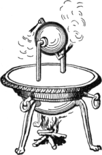
The earliest known rudimentary steam engine and reaction steam turbine, the aeolipile, is described by a mathematician and engineer named Heron of Alexandria in 1st century Roman Egypt, as recorded in his manuscript Spiritalia seu Pneumatica. Steam ejected tangentially from nozzles caused a pivoted ball to rotate. Its thermal efficiency was low. This suggests that the conversion of steam pressure into mechanical movement was known in Roman Egypt in the 1st century. Heron also devised a machine that used air heated in an altar fire to displace a quantity of water from a closed vessel. The weight of the water was made to pull a hidden rope to operate temple doors. Some historians have conflated the two inventions to assert, incorrectly, that the aeolipile was capable of useful work.

According to William of Malmesbury, in 1125, Reims was home to a church that had an organ powered by air escaping from compression "by heated water", apparently designed and constructed by professor Gerbertus.

Among the papers of Leonardo da Vinci dating to the late 15th century is the design for a steam-powered cannon called the Architonnerre, which works by the sudden influx of hot water into a sealed, red-hot cannon.

A rudimentary impact steam turbine was described in 1551 by Taqi al-Din, a philosopher, astronomer and engineer in 16th century Ottoman Egypt, who described a method for rotating a spit by means of a jet of steam playing on rotary vanes around the periphery of a wheel. A similar device for rotating a spit was also later described by John Wilkins in 1648. These devices were then called "mills" but are now known as steam jacks. Another similar rudimentary steam turbine is shown by Giovanni Branca, an Italian engineer, in 1629 for turning a cylindrical escapement device that alternately lifted and let fall a pair of pestles working in mortars. The steam flow of these early steam turbines, however, was not concentrated and most of its energy was dissipated in all directions. This would have led to a great waste of energy and so they were never seriously considered for industrial use.

In 1605 French mathematician Florence Rivault in his treatise on artillery wrote on his discovery that water, if confined in a bombshell and heated, would explode the shells.

In 1606, the Spaniard Jerónimo de Ayanz y Beaumont demonstrated and was granted a patent for a steam-powered water pump. The pump was successfully used to drain the inundated mines of Guadalcanal, Spain.

Development of the commercial steam engine

"The discoveries that, when brought together by Thomas Newcomen in 1712, resulted in the steam engine were:"

  • The concept of a vacuum (i.e. a reduction in pressure below ambient)
  • The concept of pressure
  • Techniques for creating a vacuum
  • A means of generating steam
  • The piston and cylinder

In 1643 Evangelista Torricelli conducted experiments on suction lift water pumps to test their limits, which was about 32 feet. (Atmospheric pressure is 32.9 feet or 10.03 meters. Vapor pressure of water lowers theoretical lift height.) He devised an experiment using a tube filled with mercury and inverted in a bowl of mercury (a barometer) and observed an empty space above the column of mercury, which he theorized contained nothing, that is, a vacuum.

Influenced by Torricelli, Otto von Guericke invented a vacuum pump by modifying an air pump used for pressurizing an air gun. Guericke put on a demonstration in 1654 in Magdeburg, Germany, where he was mayor. Two copper hemispheres were fitted together and air was pumped out. Weights strapped to the hemispheres could not pull them apart until the air valve was opened. The experiment was repeated in 1656 using two teams of 8 horses each, which could not separate the Magdeburg hemispheres.

Gaspar Schott was the first to describe the hemisphere experiment in his Mechanica Hydraulico-Pneumatica (1657).

After reading Schott's book, Robert Boyle built an improved vacuum pump and conducted related experiments.

Denis Papin became interested in using a vacuum to generate motive power while working with Christiaan Huygens and Gottfried Leibniz in Paris in 1663. Papin worked for Robert Boyle from 1676 to 1679, publishing an account of his work in Continuation of New Experiments (1680) and gave a presentation to Royal Society in 1689. From 1690 on Papin began experimenting with a piston to produce power with steam, building model steam engines. He experimented with atmospheric and pressure steam engines, publishing his results in 1707.

In 1663 Edward Somerset, 2nd Marquess of Worcester published a book of 100 inventions which described a method for raising water between floors employing a similar principle to that of a coffee percolator. His system was the first to separate the boiler (a heated cannon barrel) from the pumping action. Water was admitted into a reinforced barrel from a cistern, and then a valve was opened to admit steam from a separate boiler. The pressure built over the top of the water, driving it up a pipe. He installed his steam-powered device on the wall of the Great Tower at Raglan Castle to supply water through the tower. The grooves in the wall where the engine was installed were still to be seen in the 19th century. However, no one was prepared to risk money for such a revolutionary concept, and without backers the machine remained undeveloped.

Samuel Morland, a mathematician and inventor who worked on pumps, left notes at the Vauxhall Ordinance Office on a steam pump design that Thomas Savery read. In 1698 Savery built a steam pump called “The Miner’s Friend.” It employed both vacuum and pressure. These were used for low horsepower service for a number of years.

Thomas Newcomen was a merchant who dealt in cast iron goods. Newcomen's engine was based on the piston and cylinder design proposed by Papin. In Newcomen's engine steam was condensed by water sprayed inside the cylinder, causing atmospheric pressure to move the piston. Newcomen's first engine installed for pumping in a mine in 1712 at Dudley Castle in Staffordshire.

Cylinders

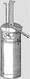
Denis Papin's design for a piston-and-cylinder engine, 1680.

Denis Papin (22 August 1647 – c. 1712) was a French physicist, mathematician and inventor, best known for his pioneering invention of the steam digester, the forerunner of the pressure cooker. In the mid-1670s Papin collaborated with the Dutch physicist Christiaan Huygens on an engine which drove out the air from a cylinder by exploding gunpowder inside it. Realising the incompleteness of the vacuum produced by this means and on moving to England in 1680, Papin devised a version of the same cylinder that obtained a more complete vacuum from boiling water and then allowing the steam to condense; in this way he was able to raise weights by attaching the end of the piston to a rope passing over a pulley. As a demonstration model the system worked, but in order to repeat the process the whole apparatus had to be dismantled and reassembled. Papin quickly saw that to make an automatic cycle the steam would have to be generated separately in a boiler; however, he did not take the project further. Papin also designed a paddle boat driven by a jet playing on a mill-wheel in a combination of Taqi al Din and Savery's conceptions and he is also credited with a number of significant devices such as the safety valve. Papin's years of research into the problems of harnessing steam was to play a key part in the development of the first successful industrial engines that soon followed his death.

Savery steam pump

The first steam engine to be applied industrially was the "fire-engine" or "Miner's Friend", designed by Thomas Savery in 1698. This was a pistonless steam pump, similar to the one developed by Worcester. Savery made two key contributions that greatly improved the practicality of the design. First, in order to allow the water supply to be placed below the engine, he used condensed steam to produce a partial vacuum in the pumping reservoir (the barrel in Worcester's example), and using that to pull the water upward. Secondly, in order to rapidly cool the steam to produce the vacuum, he ran cold water over the reservoir.

Operation required several valves; when the reservoir was empty at the start of a cycle a valve was opened to admit steam. The valve was closed to seal the reservoir and the cooling water valve turned on to condense the steam and create a partial vacuum. A supply valve was opened, pulling water upward into the reservoir, and the typical engine could pull water up to 20 feet. This was closed and the steam valve reopened, building pressure over the water and pumping it upward, as in the Worcester design. The cycle essentially doubled the distance that water could be pumped for any given pressure of steam, and production examples raised water about 40 feet.

Savery's engine solved a problem that had only recently become a serious one; raising water out of the mines in southern England as they reached greater depths. Savery's engine was somewhat less efficient than Newcomen's, but this was compensated for by the fact that the separate pump used by the Newcomen engine was inefficient, giving the two engines roughly the same efficiency of 6 million foot pounds per bushel of coal (less than 1%). Nor was the Savery engine very safe because part of its cycle required steam under pressure supplied by a boiler, and given the technology of the period the pressure vessel could not be made strong enough and so was prone to explosion. The explosion of one of his pumps at Broad Waters (near Wednesbury), about 1705, probably marks the end of attempts to exploit his invention.

The Savery engine was less expensive than Newcomen's and was produced in smaller sizes. Some builders were manufacturing improved versions of the Savery engine until late in the 18th century. Bento de Moura Portugal, FRS, introduced an ingenious improvement of Savery's construction "to render it capable of working itself", as described by John Smeaton in the Philosophical Transactions published in 1751.

Atmospheric condensing engines

Newcomen "atmospheric" engine

Engraving of Newcomen engine. This appears to be copied from a drawing in Desaguliers' 1744 work: "A course of experimental philosophy", itself believed to have been a reversed copy of Henry Beighton's engraving dated 1717, that may represent what is probably the second Newcomen engine erected around 1714 at Griff colliery, Warwickshire.

It was Thomas Newcomen with his "atmospheric-engine" of 1712 who can be said to have brought together most of the essential elements established by Papin in order to develop the first practical steam engine for which there could be a commercial demand. This took the shape of a reciprocating beam engine installed at surface level driving a succession of pumps at one end of the beam. The engine, attached by chains from other end of the beam, worked on the atmospheric, or vacuum principle.

Newcomen's design used some elements of earlier concepts. Like the Savery design, Newcomen's engine used steam, cooled with water, to create a vacuum. Unlike Savery's pump, however, Newcomen used the vacuum to pull on a piston instead of pulling on water directly. The upper end of the cylinder was open to the atmospheric pressure, and when the vacuum formed, the atmospheric pressure above the piston pushed it down into the cylinder. The piston was lubricated and sealed by a trickle of water from the same cistern that supplied the cooling water. Further, to improve the cooling effect, he sprayed water directly into the cylinder.

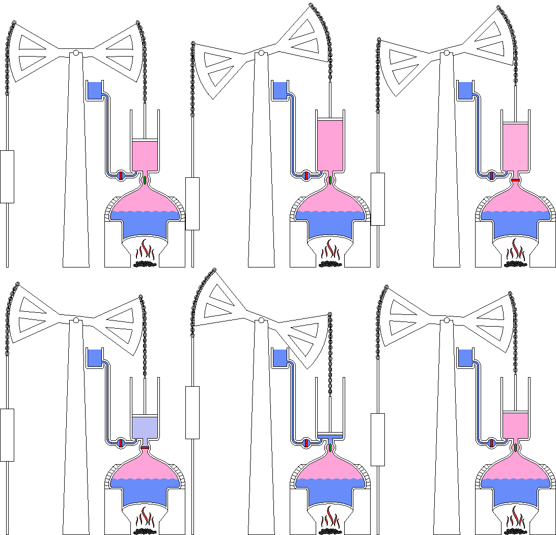
Animation of a Newcomen atmospheric engine in action

The piston was attached by a chain to a large pivoted beam. When the piston pulled the beam, the other side of the beam was pulled upward. This end was attached to a rod that pulled on a series of conventional pump handles in the mine. At the end of this power stroke, the steam valve was reopened, and the weight of the pump rods pulled the beam down, lifting the piston and drawing steam into the cylinder again.

Using the piston and beam allowed the Newcomen engine to power pumps at different levels throughout the mine, as well as eliminating the need for any high-pressure steam. The entire system was isolated to a single building on the surface. Although inefficient and extremely heavy on coal (compared to later engines), these engines raised far greater volumes of water and from greater depths than had previously been possible. Over 100 Newcomen engines were installed around England by 1735, and it is estimated that as many as 2,000 were in operation by 1800 (including Watt versions).

John Smeaton made numerous improvements to the Newcomen engine, notably the seals, and by improving these was able to almost triple their efficiency. He also preferred to use wheels instead of beams for transferring power from the cylinder, which made his engines more compact. Smeaton was the first to develop a rigorous theory of steam engine design of operation. He worked backward from the intended role to calculate the amount of power that would be needed for the task, the size and speed of a cylinder that would provide it, the size of boiler needed to feed it, and the amount of fuel it would consume. These were developed empirically after studying dozens of Newcomen engines in Cornwall and Newcastle, and building an experimental engine of his own at his home in Austhorpe in 1770. By the time the Watt engine was introduced only a few years later, Smeaton had built dozens of ever-larger engines into the 100 hp range.

Watt's separate condenser

Early Watt pumping engine.

While working at the University of Glasgow as an instrument maker and repairman in 1759, James Watt was introduced to the power of steam by Professor John Robison. Fascinated, Watt took to reading everything he could on the subject, and independently developed the concept of latent heat, only recently published by Joseph Black at the same university. When Watt learned that the University owned a small working model of a Newcomen engine, he pressed to have it returned from London where it was being unsuccessfully repaired. Watt repaired the machine, but found it was barely functional even when fully repaired.

After working with the design, Watt concluded that 80% of the steam used by the engine was wasted. Instead of providing motive force, it was instead being used to heat the cylinder. In the Newcomen design, every power stroke was started with a spray of cold water, which not only condensed the steam, but also cooled the walls of the cylinder. This heat had to be replaced before the cylinder would accept steam again. In the Newcomen engine the heat was supplied only by the steam, so when the steam valve was opened again the vast majority condensed on the cold walls as soon as it was admitted to the cylinder. It took a considerable amount of time and steam before the cylinder warmed back up and the steam started to fill it up.

Watt solved the problem of the water spray by removing the cold water to a different cylinder, placed beside the power cylinder. Once the induction stroke was complete a valve was opened between the two, and any steam that entered the cylinder would condense inside this cold cylinder. This would create a vacuum that would pull more of the steam into the cylinder, and so on until the steam was mostly condensed. The valve was then closed, and operation of the main cylinder continued as it would on a conventional Newcomen engine. As the power cylinder remained at operational temperature throughout, the system was ready for another stroke as soon as the piston was pulled back to the top. Maintaining the temperature was a jacket around the cylinder where steam was admitted. Watt produced a working model in 1765.

Convinced that this was a great advance, Watt entered into partnerships to provide venture capital while he worked on the design. Not content with this single improvement, Watt worked tirelessly on a series of other improvements to practically every part of the engine. Watt further improved the system by adding a small vacuum pump to pull the steam out of the cylinder into the condenser, further improving cycle times. A more radical change from the Newcomen design was closing off the top of the cylinder and introducing low-pressure steam above the piston. Now the power was not due to the difference of atmospheric pressure and the vacuum, but the pressure of the steam and the vacuum, a somewhat higher value. On the upward return stroke, the steam on top was transferred through a pipe to the underside of the piston ready to be condensed for the downward stroke. Sealing of the piston on a Newcomen engine had been achieved by maintaining a small quantity of water on its upper side. This was no longer possible in Watt's engine due to the presence of the steam. Watt spent considerable effort to find a seal that worked, eventually obtained by using a mixture of tallow and oil. The piston rod also passed through a gland on the top cylinder cover sealed in a similar way.

The piston sealing problem was due to having no way to produce a sufficiently round cylinder. Watt tried having cylinders bored from cast iron, but they were too out of round. Watt was forced to use a hammered iron cylinder. The following quotation is from Roe (1916):

"When [John] Smeaton first saw the engine he reported to the Society of Engineers that 'neither the tools nor the workmen existed who could manufacture such a complex machine with sufficient precision' "

Watt finally considered the design good enough to release in 1774, and the Watt engine was released to the market. As portions of the design could be easily fitted to existing Newcomen engines, there was no need to build an entirely new engine at the mines. Instead, Watt and his business partner Matthew Boulton licensed the improvements to engine operators, charging them a portion of the money they would save in reduced fuel costs. The design was wildly successful, and the Boulton and Watt company was formed to license the design and help new manufacturers build the engines. The two would later open the Soho Foundry to produce engines of their own.

In 1774 John Wilkinson invented a boring machine with the shaft holding the boring tool supported on both ends, extending through the cylinder, unlike the then used cantilevered borers. With this machine he was able to successfully bore the cylinder for Boulton and Watt's first commercial engine in 1776.

Watt never ceased improving his designs. This further improved the operating cycle speed, introduced governors, automatic valves, double-acting pistons, a variety of rotary power takeoffs and many other improvements. Watt's technology enabled the widespread commercial use of stationary steam engines.

Humphrey Gainsborough produced a model condensing steam engine in the 1760s, which he showed to Richard Lovell Edgeworth, a member of the Lunar Society. Gainsborough believed that Watt had used his ideas for the invention; however James Watt was not a member of the Lunar Society at this period and his many accounts explaining the succession of thought processes leading to the final design would tend to belie this story.

Power was still limited by the low pressure, the displacement of the cylinder, combustion and evaporation rates and condenser capacity. Maximum theoretical efficiency was limited by the relatively low temperature differential on either side of the piston; this meant that for a Watt engine to provide a usable amount of power, the first production engines had to be very large, and were thus expensive to build and install.

Watt double-acting and rotative engines

Watt developed a double-acting engine in which steam drove the piston in both directions, thereby increasing the engine speed and efficiency. The double-acting principle also significantly increased the output of a given physical sized engine.

Boulton & Watt developed the reciprocating engine into the rotative type. Unlike the Newcomen engine, the Watt engine could operate smoothly enough to be connected to a drive shaft – via sun and planet gears – to provide rotary power along with double-acting condensing cylinders. The earliest example was built as a demonstrator and was installed in Boulton's factory to work machines for lapping (polishing) buttons or similar. For this reason it was always known as the Lap Engine. In early steam engines the piston is usually connected by a rod to a balanced beam, rather than directly to a flywheel, and these engines are therefore known as beam engines.

Early steam engines did not provide constant enough speed for critical operations such as cotton spinning. To control speed the engine was used to pump water for a water wheel, which powered the machinery.

High-pressure engines

As the 18th century advanced, the call was for higher pressures; this was strongly resisted by Watt who used the monopoly his patent gave him to prevent others from building high-pressure engines and using them in vehicles. He mistrusted the boiler technology of the day, the way they were constructed and the strength of the materials used.

The important advantages of high-pressure engines were:

  1. They could be made much smaller than previously for a given power output. There was thus the potential for steam engines to be developed that were small and powerful enough to propel themselves and other objects. As a result, steam power for transportation now became a practicality in the form of ships and land vehicles, which revolutionised cargo businesses, travel, military strategy, and essentially every aspect of society.
  2. Because of their smaller size, they were much less expensive.
  3. They did not require the significant quantities of condenser cooling water needed by atmospheric engines.
  4. They could be designed to run at higher speeds, making them more suitable for powering machinery.

The disadvantages were:

  1. In the low-pressure range they were less efficient than condensing engines, especially if steam was not used expansively.
  2. They were more susceptible to boiler explosions.

The main difference between how high-pressure and low-pressure steam engines work is the source of the force that moves the piston. In the engines of Newcomen and Watt, it is the condensation of the steam that creates most of the pressure difference, causing atmospheric pressure (Newcomen) and low-pressure steam, seldom more than 7 psi boiler pressure, plus condenser vacuum (Watt), to move the piston. In a high-pressure engine, most of the pressure difference is provided by the high-pressure steam from the boiler; the low-pressure side of the piston may be at atmospheric pressure or connected to the condenser pressure. Newcomen's indicator diagram, almost all below the atmospheric line, would see a revival nearly 200 years later with the low pressure cylinder of triple expansion engines contributing about 20% of the engine power, again almost completely below the atmospheric line.

The first known advocate of "strong steam" was Jacob Leupold in his scheme for an engine that appeared in encyclopaedic works from around 1725. Various projects for steam propelled boats and vehicles also appeared throughout the century, one of the most promising being the construction of Nicolas-Joseph Cugnot, who demonstrated his "fardier" (steam wagon) in 1769. Whilst the working pressure used for this vehicle is unknown, the small size of the boiler gave insufficient steam production rate to allow the fardier to advance more than a few hundred metres at a time before having to stop to raise steam. Other projects and models were proposed, but as with William Murdoch's model of 1784, many were blocked by Boulton and Watt.

This did not apply in the US, and in 1788 a steamboat built by John Fitch operated in regular commercial service along the Delaware River between Philadelphia, Pennsylvania, and Burlington, New Jersey, carrying as many as 30 passengers. This boat could typically make 7 to 8 miles per hour, and traveled more than 2,000 miles (3,200 km) during its short length of service. The Fitch steamboat was not a commercial success, as this route was adequately covered by relatively good wagon roads. In 1802 William Symington built a practical steamboat, and in 1807 Robert Fulton used a Watt steam engine to power the first commercially successful steamboat.

Oliver Evans in his turn was in favour of "strong steam" which he applied to boat engines and to stationary uses. He was a pioneer of cylindrical boilers; however Evans' boilers did suffer several serious boiler explosions, which tended to lend weight to Watt's qualms. He founded the Pittsburgh Steam Engine Company in 1811 in Pittsburgh, Pennsylvania. The company introduced high-pressure steam engines to the riverboat trade in the Mississippi watershed.

The first high-pressure steam engine was invented in 1800 by Richard Trevithick.

The importance of raising steam under pressure (from a thermodynamic standpoint) is that it attains a higher temperature. Thus, any engine using high-pressure steam operates at a higher temperature and pressure differential than is possible with a low-pressure vacuum engine. The high-pressure engine thus became the basis for most further development of reciprocating steam technology. Even so, around the year 1800, "high pressure" amounted to what today would be considered very low pressure, i.e. 40-50 psi (276-345 kPa), the point being that the high-pressure engine in question was non-condensing, driven solely by the expansive power of the steam, and once that steam had performed work it was usually exhausted at higher-than-atmospheric pressure. The blast of the exhausting steam into the chimney could be exploited to create induced draught through the fire grate and thus increase the rate of burning, hence creating more heat in a smaller furnace, at the expense of creating back pressure on the exhaust side of the piston.

On 21 February 1804, at the Penydarren ironworks at Merthyr Tydfil in South Wales, the first self-propelled railway steam engine or steam locomotive, built by Richard Trevithick, was demonstrated.

Cornish engine and compounding

Trevithick pumping engine (Cornish system).

Around 1811 Richard Trevithick was required to update a Watt pumping engine in order to adapt it to one of his new large cylindrical Cornish boilers. When Trevithick left for South America in 1816, his improvements were continued by William Sims. In a parallel, Arthur Woolf developed a compound engine with two cylinders, so that steam expanded in a high-pressure cylinder before being released into a low-pressure one. Efficiency was further improved by Samuel Groase, who insulated the boiler, engine, and pipes.

Steam pressure above the piston was increased eventually reaching 40 psi (0.28 MPa) or even 50 psi (0.34 MPa) and now provided much of the power for the downward stroke; at the same time condensing was improved. This considerably raised efficiency and further pumping engines on the Cornish system (often known as Cornish engines) continued to be built new throughout the 19th century. Older Watt engines were updated to conform.

The take-up of these Cornish improvements was slow in textile manufacturing areas where coal was cheap, due to the higher capital cost of the engines and the greater wear that they suffered. The change only began in the 1830s, usually by compounding through adding another (high-pressure) cylinder.

Another limitation of early steam engines was speed variability, which made them unsuitable for many textile applications, especially spinning. In order to obtain steady speeds, early steam powered textile mills used the steam engine to pump water to a water wheel, which drove the machinery.

Many of these engines were supplied worldwide and gave reliable and efficient service over a great many years with greatly reduced coal consumption. Some of them were very large and the type continued to be built right down to the 1890s.

Corliss engine

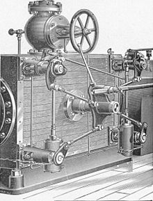
"Gordon's improved Corliss valvegear", detailed view. The wrist-plate is the central plate from which rods radiate to each of the 4 valves.

The Corliss steam engine (patented 1849) was called the greatest improvement since James Watt. The Corliss engine had greatly improved speed control and better efficiency, making it suitable to all sorts of industrial applications, including spinning.

Corliss used separate ports for steam supply and exhaust, which prevented the exhaust from cooling the passage used by the hot steam. Corliss also used partially rotating valves that provided quick action, helping to reduce pressure losses. The valves themselves were also a source of reduced friction, especially compared to the slide valve, which typically used 10% of an engine's power.

Corliss used automatic variable cut off. The valve gear controlled engine speed by using the governor to vary the timing of the cut off. This was partly responsible for the efficiency improvement in addition to the better speed control.

Porter-Allen high speed steam engine

Porter-Allen high speed engine. Enlarge to see the Porter governor at left front of flywheel

The Porter-Allen engine, introduced in 1862, used an advanced valve gear mechanism developed for Porter by Allen, a mechanic of exceptional ability, and was at first generally known as the Allen engine. The high speed engine was a precision machine that was well balanced, achievements made possible by advancements in machine tools and manufacturing technology.

The high speed engine ran at piston speeds from three to five times the speed of ordinary engines. It also had low speed variability. The high speed engine was widely used in sawmills to power circular saws. Later it was used for electrical generation.

The engine had several advantages. It could, in some cases, be directly coupled. If gears or belts and drums were used, they could be much smaller sizes. The engine itself was also small for the amount of power it developed.

Porter greatly improved the fly-ball governor by reducing the rotating weight and adding a weight around the shaft. This significantly improved speed control. Porter's governor became the leading type by 1880.

The efficiency of the Porter-Allen engine was good, but not equal to the Corliss engine.

Uniflow (or unaflow) engine

The uniflow engine was the most efficient type of high-pressure engine. It was invented in 1911 and was used in ships, but was displaced by steam turbines and later marine diesel engines.


Lie point symmetry

From Wikipedia, the free encyclopedia https://en.wikipedia.org/wiki/Lie_point_symmetry     ...