Search This Blog

Friday, May 17, 2019

Nuclear chain reaction

From Wikipedia, the free encyclopedia

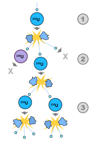
A possible nuclear fission chain reaction. 1. A uranium-235 atom absorbs a neutron, and fissions into two new atoms (fission fragments), releasing three new neutrons and a large amount of binding energy. 2. One of those neutrons is absorbed by an atom of uranium-238, and does not continue the reaction. Another neutron leaves the system without being absorbed. However, one neutron does collide with an atom of uranium-235, which then fissions and releases two neutrons and more binding energy. 3. Both of those neutrons collide with uranium-235 atoms, each of which fissions and releases a few neutrons, which can then continue the reaction.
 
A nuclear chain reaction occurs when one single nuclear reaction causes an average of one or more subsequent nuclear reactions, this leading to the possibility of a self-propagating series of these reactions. The specific nuclear reaction may be the fission of heavy isotopes (e.g., uranium-235, 235U). The nuclear chain reaction releases several million times more energy per reaction than any chemical reaction.

History

Chemical chain reactions were first proposed by German chemist Max Bodenstein in 1913, and were reasonably well understood before nuclear chain reactions were proposed. It was understood that chemical chain reactions were responsible for exponentially increasing rates in reactions, such as produced in chemical explosions. 

The concept of a nuclear chain reaction was reportedly first hypothesized by Hungarian scientist Leó Szilárd on September 12, 1933. Szilárd that morning had been reading in a London paper of an experiment in which protons from an accelerator had been used to split lithium-7 into alpha particles, and the fact that much greater amounts of energy were produced by the reaction than the proton supplied. Ernest Rutherford commented in the article that inefficiencies in the process precluded use of it for power generation. However, the neutron had been discovered in 1932, shortly before, as the product of a nuclear reaction. Szilárd, who had been trained as an engineer and physicist, put the two nuclear experimental results together in his mind and realized that if a nuclear reaction produced neutrons, which then caused further similar nuclear reactions, the process might be a self-perpetuating nuclear chain-reaction, spontaneously producing new isotopes and power without the need for protons or an accelerator. Szilárd, however, did not propose fission as the mechanism for his chain reaction, since the fission reaction was not yet discovered, or even suspected. Instead, Szilárd proposed using mixtures of lighter known isotopes which produced neutrons in copious amounts. He filed a patent for his idea of a simple nuclear reactor the following year.

In 1936, Szilárd attempted to create a chain reaction using beryllium and indium, but was unsuccessful. Nuclear fission was discovered and proved by Otto Hahn and Fritz Strassmann in December 1938. A few months later, Frédéric Joliot, H. Von Halban and L. Kowarski in Paris searched for, and discovered, neutron multiplication in uranium, proving that a nuclear chain reaction by this mechanism was indeed possible. 

On May 4, 1939 Joliot, Halban et Kowarski filed three patents. The first two described power production from a nuclear chain reaction, the last one called "Perfectionnement aux charges explosives" was the first patent for the atomic bomb and is filed as patent n°445686 by the Caisse nationale de Recherche Scientifique.

In parallel, Szilárd and Enrico Fermi in New York made the same analysis. This discovery prompted the letter from Szilárd and signed by Albert Einstein to President Franklin D. Roosevelt, warning of the possibility that Nazi Germany might be attempting to build an atomic bomb.

On December 2, 1942, a team led by Enrico Fermi (and including Szilárd) produced the first artificial self-sustaining nuclear chain reaction with the Chicago Pile-1 (CP-1) experimental reactor in a racquets court below the bleachers of Stagg Field at the University of Chicago. Fermi's experiments at the University of Chicago were part of Arthur H. Compton's Metallurgical Laboratory of the Manhattan Project; the lab was later renamed Argonne National Laboratory, and tasked with conducting research in harnessing fission for nuclear energy.

In 1956, Paul Kuroda of the University of Arkansas postulated that a natural fission reactor may have once existed. Since nuclear chain reactions may only require natural materials (such as water and uranium, if the uranium has sufficient amounts of U-235), it was possible to have these chain reactions occur in the distant past when uranium-235 concentrations were higher than today, and where there was the right combination of materials within the Earth's crust. Kuroda's prediction was verified with the discovery of evidence of natural self-sustaining nuclear chain reactions in the past at Oklo in Gabon, Africa, in September 1972.

Fission chain reaction

Fission chain reactions occur because of interactions between neutrons and fissile isotopes (such as 235U). The chain reaction requires both the release of neutrons from fissile isotopes undergoing nuclear fission and the subsequent absorption of some of these neutrons in fissile isotopes. When an atom undergoes nuclear fission, a few neutrons (the exact number depends on uncontrollable and unmeasurable factors; the expected number depends on several factors, usually between 2.5 and 3.0) are ejected from the reaction. These free neutrons will then interact with the surrounding medium, and if more fissile fuel is present, some may be absorbed and cause more fissions. Thus, the cycle repeats to give a reaction that is self-sustaining. 

Nuclear power plants operate by precisely controlling the rate at which nuclear reactions occur, and that control is maintained through the use of several redundant layers of safety measures. Moreover, the materials in a nuclear reactor core and the uranium enrichment level make a nuclear explosion impossible, even if all safety measures failed. On the other hand, nuclear weapons are specifically engineered to produce a reaction that is so fast and intense it cannot be controlled after it has started. When properly designed, this uncontrolled reaction can lead to an explosive energy release.

Nuclear fission fuel

Nuclear weapons employ high quality, highly enriched fuel exceeding the critical size and geometry (critical mass) necessary in order to obtain an explosive chain reaction. The fuel for energy purposes, such as in a nuclear fission reactor, is very different, usually consisting of a low-enriched oxide material (e.g. UO2).

Fission reaction products

When a fissile atom undergoes nuclear fission, it breaks into two or more fission fragments. Also, several free neutrons, gamma rays, and neutrinos are emitted, and a large amount of energy is released. The sum of the rest masses of the fission fragments and ejected neutrons is less than the sum of the rest masses of the original atom and incident neutron (of course the fission fragments are not at rest). The mass difference is accounted for in the release of energy according to the equation Emc2
 
mass of released energy =

Due to the extremely large value of the speed of light, c, a small decrease in mass is associated with a tremendous release of active energy (for example, the kinetic energy of the fission fragments). This energy (in the form of radiation and heat) carries the missing mass, when it leaves the reaction system (total mass, like total energy, is always conserved). While typical chemical reactions release energies on the order of a few eVs (e.g. the binding energy of the electron to hydrogen is 13.6 eV), nuclear fission reactions typically release energies on the order of hundreds of millions of eVs.

Two typical fission reactions are shown below with average values of energy released and number of neutrons ejected:
Note that these equations are for fissions caused by slow-moving (thermal) neutrons. The average energy released and number of neutrons ejected is a function of the incident neutron speed. Also, note that these equations exclude energy from neutrinos since these subatomic particles are extremely non-reactive and, therefore, rarely deposit their energy in the system.

Timescales of nuclear chain reactions

Prompt neutron lifetime

The prompt neutron lifetime, l, is the average time between the emission of neutrons and either their absorption in the system or their escape from the system. The neutrons that occur directly from fission are called "prompt neutrons," and the ones that are a result of radioactive decay of fission fragments are called "delayed neutrons". The term lifetime is used because the emission of a neutron is often considered its "birth," and the subsequent absorption is considered its "death". For thermal (slow-neutron) fission reactors, the typical prompt neutron lifetime is on the order of 10−4 seconds, and for fast fission reactors, the prompt neutron lifetime is on the order of 10−7 seconds. These extremely short lifetimes mean that in 1 second, 10,000 to 10,000,000 neutron lifetimes can pass. The average (also referred to as the adjoint unweighted) prompt neutron lifetime takes into account all prompt neutrons regardless of their importance in the reactor core; the effective prompt neutron lifetime (referred to as the adjoint weighted over space, energy, and angle) refers to a neutron with average importance.

Mean generation time

The mean generation time, Λ, is the average time from a neutron emission to a capture that results in fission. The mean generation time is different from the prompt neutron lifetime because the mean generation time only includes neutron absorptions that lead to fission reactions (not other absorption reactions). The two times are related by the following formula:
In this formula, k is the effective neutron multiplication factor, described below.

Effective neutron multiplication factor

The six factor formula effective neutron multiplication factor, k, is the average number of neutrons from one fission that cause another fission. The remaining neutrons either are absorbed in non-fission reactions or leave the system without being absorbed. The value of k determines how a nuclear chain reaction proceeds:
  • k < 1 (subcriticality): The system cannot sustain a chain reaction, and any beginning of a chain reaction dies out over time. For every fission that is induced in the system, an average total of 1/(1 − k) fissions occur.
  • k = 1 (criticality): Every fission causes an average of one more fission, leading to a fission (and power) level that is constant. Nuclear power plants operate with k = 1 unless the power level is being increased or decreased.
  • k > 1 (supercriticality): For every fission in the material, it is likely that there will be "k" fissions after the next mean generation time (Λ). The result is that the number of fission reactions increases exponentially, according to the equation , where t is the elapsed time. Nuclear weapons are designed to operate under this state. There are two subdivisions of supercriticality: prompt and delayed.
When describing kinetics and dynamics of nuclear reactors, and also in the practice of reactor operation, the concept of reactivity is used, which characterizes the deflection of reactor from the critical state. ρ=(k-1)/k. InHour is a unit of reactivity of a nuclear reactor. 

In a nuclear reactor, k will actually oscillate from slightly less than 1 to slightly more than 1, due primarily to thermal effects (as more power is produced, the fuel rods warm and thus expand, lowering their capture ratio, and thus driving k lower). This leaves the average value of k at exactly 1. Delayed neutrons play an important role in the timing of these oscillations. 

In an infinite medium, the multiplication factor may be described by the four factor formula; in a non-infinite medium, the multiplication factor may be described by the six factor formula.

Prompt and delayed supercriticality

Not all neutrons are emitted as a direct product of fission; some are instead due to the radioactive decay of some of the fission fragments. The neutrons that occur directly from fission are called "prompt neutrons," and the ones that are a result of radioactive decay of fission fragments are called "delayed neutrons". The fraction of neutrons that are delayed is called β, and this fraction is typically less than 1% of all the neutrons in the chain reaction.

The delayed neutrons allow a nuclear reactor to respond several orders of magnitude more slowly than just prompt neutrons would alone. Without delayed neutrons, changes in reaction rates in nuclear reactors would occur at speeds that are too fast for humans to control.

The region of supercriticality between k = 1 and k = 1/(1-β) is known as delayed supercriticality (or delayed criticality). It is in this region that all nuclear power reactors operate. The region of supercriticality for k > 1/(1-β) is known as prompt supercriticality (or prompt criticality), which is the region in which nuclear weapons operate.

The change in k needed to go from critical to prompt critical is defined as a dollar.

Nuclear weapons application of neutron multiplication

Nuclear fission weapons require a mass of fissile fuel that is prompt supercritical. 

For a given mass of fissile material the value of k can be increased by increasing the density. Since the probability per distance traveled for a neutron to collide with a nucleus is proportional to the material density, increasing the density of a fissile material can increase k. This concept is utilized in the implosion method for nuclear weapons. In these devices, the nuclear chain reaction begins after increasing the density of the fissile material with a conventional explosive. 

In the gun-type fission weapon two subcritical pieces of fuel are rapidly brought together. The value of k for a combination of two masses is always greater than that of its components. The magnitude of the difference depends on distance, as well as the physical orientation.

The value of k can also be increased by using a neutron reflector surrounding the fissile material.

Once the mass of fuel is prompt supercritical, the power increases exponentially. However, the exponential power increase cannot continue for long since k decreases when the amount of fission material that is left decreases (i.e. it is consumed by fissions). Also, the geometry and density are expected to change during detonation since the remaining fission material is torn apart from the explosion.

Predetonation

If two pieces of subcritical material are not brought together fast enough, nuclear predetonation can occur, whereby a smaller explosion than expected will blow the bulk of the material apart.
 
Detonation of a nuclear weapon involves bringing fissile material into its optimal supercritical state very rapidly. During part of this process, the assembly is supercritical, but not yet in an optimal state for a chain reaction. Free neutrons, in particular from spontaneous fissions, can cause the device to undergo a preliminary chain reaction that destroys the fissile material before it is ready to produce a large explosion, which is known as predetonation.

To keep the probability of predetonation low, the duration of the non-optimal assembly period is minimized and fissile and other materials are used which have low spontaneous fission rates. In fact, the combination of materials has to be such that it is unlikely that there is even a single spontaneous fission during the period of supercritical assembly. In particular, the gun method cannot be used with plutonium.

Nuclear power plants and control of chain reactions

Chain reactions naturally give rise to reaction rates that grow (or shrink) exponentially, whereas a nuclear power reactor needs to be able to hold the reaction rate reasonably constant. To maintain this control, the chain reaction criticality must have a slow enough time-scale to permit intervention by additional effects (e.g., mechanical control rods or thermal expansion). Consequently, all nuclear power reactors (even fast-neutron reactors) rely on delayed neutrons for their criticality. An operating nuclear power reactor fluctuates between being slightly subcritical and slightly delayed-supercritical, but must always remain below prompt-critical. 

It is impossible for a nuclear power plant to undergo a nuclear chain reaction that results in an explosion of power comparable with a nuclear weapon, but even low-powered explosions due to uncontrolled chain reactions, that would be considered "fizzles" in a bomb, may still cause considerable damage and meltdown in a reactor. For example, the Chernobyl disaster involved a runaway chain reaction but the result was a low-powered steam explosion from the relatively small release of heat, as compared with a bomb. However, the reactor complex was destroyed by the heat, as well as by ordinary burning of the graphite exposed to air. Such steam explosions would be typical of the very diffuse assembly of materials in a nuclear reactor, even under the worst conditions.

In addition, other steps can be taken for safety. For example, power plants licensed in the United States require a negative void coefficient of reactivity (this means that if water is removed from the reactor core, the nuclear reaction will tend to shut down, not increase). This eliminates the possibility of the type of accident that occurred at Chernobyl (which was due to a positive void coefficient). However, nuclear reactors are still capable of causing smaller explosions even after complete shutdown, such as was the case of the Fukushima Daiichi nuclear disaster. In such cases, residual decay heat from the core may cause high temperatures if there is loss of coolant flow, even a day after the chain reaction has been shut down (see SCRAM). This may cause a chemical reaction between water and fuel that produces hydrogen gas which can explode after mixing with air, with severe contamination consequences, since fuel rod material may still be exposed to the atmosphere from this process. However, such explosions do not happen during a chain reaction, but rather as a result of energy from radioactive beta decay, after the fission chain reaction has been stopped.
Emission spectrum


From Wikipedia, the free encyclopedia
Emission spectrum of a metal halide lamp.
 
A demonstration of the 589 nm D2 (left) and 590 nm D1 (right) emission sodium D lines using a wick with salt water in a flame
 
The emission spectrum of a chemical element or chemical compound is the spectrum of frequencies of electromagnetic radiation emitted due to an atom or molecule making a transition from a high energy state to a lower energy state. The photon energy of the emitted photon is equal to the energy difference between the two states. There are many possible electron transitions for each atom, and each transition has a specific energy difference. This collection of different transitions, leading to different radiated wavelengths, make up an emission spectrum. Each element's emission spectrum is unique. Therefore, spectroscopy can be used to identify the elements in matter of unknown composition. Similarly, the emission spectra of molecules can be used in chemical analysis of substances.

Emission

In physics, emission is the process by which a higher energy quantum mechanical state of a particle becomes converted to a lower one through the emission of a photon, resulting in the production of light. The frequency of light emitted is a function of the energy of the transition. Since energy must be conserved, the energy difference between the two states equals the energy carried off by the photon. The energy states of the transitions can lead to emissions over a very large range of frequencies. For example, visible light is emitted by the coupling of electronic states in atoms and molecules (then the phenomenon is called fluorescence or phosphorescence). On the other hand, nuclear shell transitions can emit high energy gamma rays, while nuclear spin transitions emit low energy radio waves

The emittance of an object quantifies how much light is emitted by it. This may be related to other properties of the object through the Stefan–Boltzmann law. For most substances, the amount of emission varies with the temperature and the spectroscopic composition of the object, leading to the appearance of color temperature and emission lines. Precise measurements at many wavelengths allow the identification of a substance via emission spectroscopy

Emission of radiation is typically described using semi-classical quantum mechanics: the particle's energy levels and spacings are determined from quantum mechanics, and light is treated as an oscillating electric field that can drive a transition if it is in resonance with the system's natural frequency. The quantum mechanics problem is treated using time-dependent perturbation theory and leads to the general result known as Fermi's golden rule. The description has been superseded by quantum electrodynamics, although the semi-classical version continues to be more useful in most practical computations.

Origins

When the electrons in the atom are excited, for example by being heated, the additional energy pushes the electrons to higher energy orbitals. When the electrons fall back down and leave the excited state, energy is re-emitted in the form of a photon. The wavelength (or equivalently, frequency) of the photon is determined by the difference in energy between the two states. These emitted photons form the element's spectrum. 

The fact that only certain colors appear in an element's atomic emission spectrum means that only certain frequencies of light are emitted. Each of these frequencies are related to energy by the formula:
,
where is the energy of the photon, is its frequency, and is Planck's constant. This concludes that only photons with specific energies are emitted by the atom. The principle of the atomic emission spectrum explains the varied colors in neon signs, as well as chemical flame test results (described below). 

The frequencies of light that an atom can emit are dependent on states the electrons can be in. When excited, an electron moves to a higher energy level or orbital. When the electron falls back to its ground level the light is emitted. 

Emission spectrum of hydrogen
 
The above picture shows the visible light emission spectrum for hydrogen. If only a single atom of hydrogen were present, then only a single wavelength would be observed at a given instant. Several of the possible emissions are observed because the sample contains many hydrogen atoms that are in different initial energy states and reach different final energy states. These different combinations lead to simultaneous emissions at different wavelengths. 

Emission spectrum of iron

Radiation from molecules

As well as the electronic transitions discussed above, the energy of a molecule can also change via rotational, vibrational, and vibronic (combined vibrational and electronic) transitions. These energy transitions often lead to closely spaced groups of many different spectral lines, known as spectral bands. Unresolved band spectra may appear as a spectral continuum.

Emission spectroscopy

Light consists of electromagnetic radiation of different wavelengths. Therefore, when the elements or their compounds are heated either on a flame or by an electric arc they emit energy in the form of light. Analysis of this light, with the help of a spectroscope gives us a discontinuous spectrum. A spectroscope or a spectrometer is an instrument which is used for separating the components of light, which have different wavelengths. The spectrum appears in a series of lines called the line spectrum. This line spectrum is called an atomic spectrum when it originates from an atom in elemental form. Each element has a different atomic spectrum. The production of line spectra by the atoms of an element indicate that an atom can radiate only a certain amount of energy. This leads to the conclusion that bound electrons cannot have just any amount of energy but only a certain amount of energy. 

The emission spectrum can be used to determine the composition of a material, since it is different for each element of the periodic table. One example is astronomical spectroscopy: identifying the composition of stars by analysing the received light. The emission spectrum characteristics of some elements are plainly visible to the naked eye when these elements are heated. For example, when platinum wire is dipped into a strontium nitrate solution and then inserted into a flame, the strontium atoms emit a red color. Similarly, when copper is inserted into a flame, the flame becomes green. These definite characteristics allow elements to be identified by their atomic emission spectrum. Not all emitted lights are perceptible to the naked eye, as the spectrum also includes ultraviolet rays and infrared lighting. An emission is formed when an excited gas is viewed directly through a spectroscope. 

Schematic diagram of spontaneous emission
 
Emission spectroscopy is a spectroscopic technique which examines the wavelengths of photons emitted by atoms or molecules during their transition from an excited state to a lower energy state. Each element emits a characteristic set of discrete wavelengths according to its electronic structure, and by observing these wavelengths the elemental composition of the sample can be determined. Emission spectroscopy developed in the late 19th century and efforts in theoretical explanation of atomic emission spectra eventually led to quantum mechanics.

There are many ways in which atoms can be brought to an excited state. Interaction with electromagnetic radiation is used in fluorescence spectroscopy, protons or other heavier particles in Particle-Induced X-ray Emission and electrons or X-ray photons in Energy-dispersive X-ray spectroscopy or X-ray fluorescence. The simplest method is to heat the sample to a high temperature, after which the excitations are produced by collisions between the sample atoms. This method is used in flame emission spectroscopy, and it was also the method used by Anders Jonas Ångström when he discovered the phenomenon of discrete emission lines in the 1850s.

Although the emission lines are caused by a transition between quantized energy states and may at first look very sharp, they do have a finite width, i.e. they are composed of more than one wavelength of light. This spectral line broadening has many different causes.

Emission spectroscopy is often referred to as optical emission spectroscopy because of the light nature of what is being emitted.

History

Emission lines from hot gases were first discovered by Ångström, and the technique was further developed by David Alter, Gustav Kirchhoff and Robert Bunsen.

Experimental technique in flame emission spectroscopy

The solution containing the relevant substance to be analysed is drawn into the burner and dispersed into the flame as a fine spray. The solvent evaporates first, leaving finely divided solid particles which move to the hottest region of the flame where gaseous atoms and ions are produced. Here electrons are excited as described above. It is common for a monochromator to be used to allow for easy detection.

On a simple level, flame emission spectroscopy can be observed using just a flame and samples of metal salts. This method of qualitative analysis is called a flame test. For example, sodium salts placed in the flame will glow yellow from sodium ions, while strontium (used in road flares) ions color it red. Copper wire will create a blue colored flame, however in the presence of chloride gives green (molecular contribution by CuCl).

Emission coefficient

Emission coefficient is a coefficient in the power output per unit time of an electromagnetic source, a calculated value in physics. The emission coefficient of a gas varies with the wavelength of the light. It has units of ms−3sr−1. It is also used as a measure of environmental emissions (by mass) per MWh of electricity generated.

Scattering of light

In Thomson scattering a charged particle emits radiation under incident light. The particle may be an ordinary atomic electron, so emission coefficients have practical applications.

If X dV dΩ dλ is the energy scattered by a volume element dV into solid angle dΩ between wavelengths λ and λ+dλ per unit time then the Emission coefficient is X

The values of X in Thomson scattering can be predicted from incident flux, the density of the charged particles and their Thomson differential cross section (area/solid angle).

Spontaneous emission

A warm body emitting photons has a monochromatic emission coefficient relating to its temperature and total power radiation. This is sometimes called the second Einstein coefficient, and can be deduced from quantum mechanical theory.

X-ray fluorescence

From Wikipedia, the free encyclopedia

X-Ray Fluorescence for Metallic coatings
 
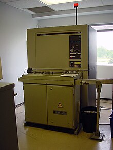
A Philips PW1606 X-ray fluorescence spectrometer with automated sample feed in a cement plant quality control laboratory
 
X-ray fluorescence (XRF) is the emission of characteristic "secondary" (or fluorescent) X-rays from a material that has been excited by being bombarded with high-energy X-rays or gamma rays. The phenomenon is widely used for elemental analysis and chemical analysis, particularly in the investigation of metals, glass, ceramics and building materials, and for research in geochemistry, forensic science, archaeology and art objects such as paintings and murals.

Underlying physics

Figure 1: Physics of X-ray fluorescence in a schematic representation.
 
When materials are exposed to short-wavelength X-rays or to gamma rays, ionization of their component atoms may take place. Ionization consists of the ejection of one or more electrons from the atom, and may occur if the atom is exposed to radiation with an energy greater than its ionization energy. X-rays and gamma rays can be energetic enough to expel tightly held electrons from the inner orbitals of the atom. The removal of an electron in this way makes the electronic structure of the atom unstable, and electrons in higher orbitals "fall" into the lower orbital to fill the hole left behind. In falling, energy is released in the form of a photon, the energy of which is equal to the energy difference of the two orbitals involved. Thus, the material emits radiation, which has energy characteristic of the atoms present. The term fluorescence is applied to phenomena in which the absorption of radiation of a specific energy results in the re-emission of radiation of a different energy (generally lower). 

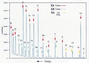
Figure 2: Typical wavelength dispersive XRF spectrum
 
Figure 3: Spectrum of a rhodium target tube operated at 60 kV, showing continuous spectrum and K lines

Characteristic radiation

Each element has electronic orbitals of characteristic energy. Following removal of an inner electron by an energetic photon provided by a primary radiation source, an electron from an outer shell drops into its place. There are a limited number of ways in which this can happen, as shown in Figure 1. The main transitions are given names: an L→K transition is traditionally called Kα, an M→K transition is called Kβ, an M→L transition is called Lα, and so on. Each of these transitions yields a fluorescent photon with a characteristic energy equal to the difference in energy of the initial and final orbital. The wavelength of this fluorescent radiation can be calculated from Planck's Law:
The fluorescent radiation can be analysed either by sorting the energies of the photons (energy-dispersive analysis) or by separating the wavelengths of the radiation (wavelength-dispersive analysis). Once sorted, the intensity of each characteristic radiation is directly related to the amount of each element in the material. This is the basis of a powerful technique in analytical chemistry. Figure 2 shows the typical form of the sharp fluorescent spectral lines obtained in the wavelength-dispersive method.

Primary radiation

In order to excite the atoms, a source of radiation is required, with sufficient energy to expel tightly held inner electrons. Conventional X-ray generators are most commonly used, because their output can readily be "tuned" for the application, and because higher power can be deployed relative to other techniques. However, gamma ray sources can be used without the need for an elaborate power supply, allowing an easier use in small portable instruments. When the energy source is a synchrotron or the X-rays are focused by an optic like a polycapillary, the X-ray beam can be very small and very intense. As a result, atomic information on the sub-micrometre scale can be obtained. X-ray generators in the range 20–60 kV are used, which allow excitation of a broad range of atoms. The continuous spectrum consists of "bremsstrahlung" radiation: radiation produced when high-energy electrons passing through the tube are progressively decelerated by the material of the tube anode (the "target"). A typical tube output spectrum is shown in Figure 3.

Dispersion

In energy dispersive analysis, the fluorescent X-rays emitted by the material sample are directed into a solid-state detector which produces a "continuous" distribution of pulses, the voltages of which are proportional to the incoming photon energies. This signal is processed by a multichannel analyser (MCA) which produces an accumulating digital spectrum that can be processed to obtain analytical data. 

In wavelength dispersive analysis, the fluorescent X-rays emitted by the material sample are directed into a diffraction grating monochromator. The diffraction grating used is usually a single crystal. By varying the angle of incidence and take-off on the crystal, a single X-ray wavelength can be selected. The wavelength obtained is given by Bragg's law:
where d is the spacing of atomic layers parallel to the crystal surface.

Detection

A portable XRF analyzer using a Silicon drift detector
 
In energy dispersive analysis, dispersion and detection are a single operation, as already mentioned above. Proportional counters or various types of solid-state detectors (PIN diode, Si(Li), Ge(Li), Silicon Drift Detector SDD) are used. They all share the same detection principle: An incoming X-ray photon ionises a large number of detector atoms with the amount of charge produced being proportional to the energy of the incoming photon. The charge is then collected and the process repeats itself for the next photon. Detector speed is obviously critical, as all charge carriers measured have to come from the same photon to measure the photon energy correctly (peak length discrimination is used to eliminate events that seem to have been produced by two X-ray photons arriving almost simultaneously). The spectrum is then built up by dividing the energy spectrum into discrete bins and counting the number of pulses registered within each energy bin. EDXRF detector types vary in resolution, speed and the means of cooling (a low number of free charge carriers is critical in the solid state detectors): proportional counters with resolutions of several hundred eV cover the low end of the performance spectrum, followed by PIN diode detectors, while the Si(Li), Ge(Li) and Silicon Drift Detectors (SDD) occupy the high end of the performance scale.

In wavelength dispersive analysis, the single-wavelength radiation produced by the monochromator is passed into a photomultiplier, a detector similar to a Geiger counter, which counts individual photons as they pass through. The counter is a chamber containing a gas that is ionised by X-ray photons. A central electrode is charged at (typically) +1700 V with respect to the conducting chamber walls, and each photon triggers a pulse-like cascade of current across this field. The signal is amplified and transformed into an accumulating digital count. These counts are then processed to obtain analytical data.

X-ray intensity

The fluorescence process is inefficient, and the secondary radiation is much weaker than the primary beam. Furthermore, the secondary radiation from lighter elements is of relatively low energy (long wavelength) and has low penetrating power, and is severely attenuated if the beam passes through air for any distance. Because of this, for high-performance analysis, the path from tube to sample to detector is maintained under vacuum (around 10 Pa residual pressure). This means in practice that most of the working parts of the instrument have to be located in a large vacuum chamber. The problems of maintaining moving parts in vacuum, and of rapidly introducing and withdrawing the sample without losing vacuum, pose major challenges for the design of the instrument. For less demanding applications, or when the sample is damaged by a vacuum (e.g. a volatile sample), a helium-swept X-ray chamber can be substituted, with some loss of low-Z (Z = atomic number) intensities.

Chemical analysis

The use of a primary X-ray beam to excite fluorescent radiation from the sample was first proposed by Glocker and Schreiber in 1928. Today, the method is used as a non-destructive analytical technique, and as a process control tool in many extractive and processing industries. In principle, the lightest element that can be analysed is beryllium (Z = 4), but due to instrumental limitations and low X-ray yields for the light elements, it is often difficult to quantify elements lighter than sodium (Z = 11), unless background corrections and very comprehensive inter-element corrections are made.

Figure 4: Schematic arrangement of EDX spectrometer

Energy dispersive spectrometry

In energy dispersive spectrometers (EDX or EDS), the detector allows the determination of the energy of the photon when it is detected. Detectors historically have been based on silicon semiconductors, in the form of lithium-drifted silicon crystals, or high-purity silicon wafers. 

Figure 5: Schematic form of a Si(Li) detector

Si(Li) detectors

These consist essentially of a 3–5 mm thick silicon junction type p-i-n diode (same as PIN diode) with a bias of −1000 V across it. The lithium-drifted centre part forms the non-conducting i-layer, where Li compensates the residual acceptors which would otherwise make the layer p-type. When an X-ray photon passes through, it causes a swarm of electron-hole pairs to form, and this causes a voltage pulse. To obtain sufficiently low conductivity, the detector must be maintained at low temperature, and liquid-nitrogen cooling must be used for the best resolution. With some loss of resolution, the much more convenient Peltier cooling can be employed.

Wafer detectors

More recently, high-purity silicon wafers with low conductivity have become routinely available. Cooled by the Peltier effect, this provides a cheap and convenient detector, although the liquid nitrogen cooled Si(Li) detector still has the best resolution (i.e. ability to distinguish different photon energies).

Amplifiers

The pulses generated by the detector are processed by pulse-shaping amplifiers. It takes time for the amplifier to shape the pulse for optimum resolution, and there is therefore a trade-off between resolution and count-rate: long processing time for good resolution results in "pulse pile-up" in which the pulses from successive photons overlap. Multi-photon events are, however, typically more drawn out in time (photons did not arrive exactly at the same time) than single photon events and pulse-length discrimination can thus be used to filter most of these out. Even so, a small number of pile-up peaks will remain and pile-up correction should be built into the software in applications that require trace analysis. To make the most efficient use of the detector, the tube current should be reduced to keep multi-photon events (before discrimination) at a reasonable level, e.g. 5–20%.

Processing

Considerable computer power is dedicated to correcting for pulse-pile up and for extraction of data from poorly resolved spectra. These elaborate correction processes tend to be based on empirical relationships that may change with time, so that continuous vigilance is required in order to obtain chemical data of adequate precision.

Usage

EDX spectrometers are different from WDX spectrometers in that they are smaller, simpler in design and have fewer engineered parts, however the accuracy and resolution of EDX spectrometers are lower than for WDX. EDX spectrometers can also use miniature X-ray tubes or gamma sources, which makes them cheaper and allows miniaturization and portability. This type of instrument is commonly used for portable quality control screening applications, such as testing toys for lead (Pb) content, sorting scrap metals, and measuring the lead content of residential paint. On the other hand, the low resolution and problems with low count rate and long dead-time makes them inferior for high-precision analysis. They are, however, very effective for high-speed, multi-elemental analysis. Field Portable XRF analysers currently on the market weigh less than 2 kg, and have limits of detection on the order of 2 parts per million of lead (Pb) in pure sand. Using a Scanning Electron Microscope and using EDX, studies have been broadened to organic based samples such as biological samples and polymers. 

Figure 6: Schematic arrangement of wavelength dispersive spectrometer
 
Chemist operates a goniometer used for X-ray fluorescence analysis of individual grains of mineral specimens, U.S. Geological Survey, 1958.

Wavelength dispersive spectrometry

In wavelength dispersive spectrometers (WDX or WDS), the photons are separated by diffraction on a single crystal before being detected. Although wavelength dispersive spectrometers are occasionally used to scan a wide range of wavelengths, producing a spectrum plot as in EDS, they are usually set up to make measurements only at the wavelength of the emission lines of the elements of interest. This is achieved in two different ways:
  • "Simultaneous" spectrometers have a number of "channels" dedicated to analysis of a single element, each consisting of a fixed-geometry crystal monochromator, a detector, and processing electronics. This allows a number of elements to be measured simultaneously, and in the case of high-powered instruments, complete high-precision analyses can be obtained in under 30 s. Another advantage of this arrangement is that the fixed-geometry monochromators have no continuously moving parts, and so are very reliable. Reliability is important in production environments where instruments are expected to work without interruption for months at a time. Disadvantages of simultaneous spectrometers include relatively high cost for complex analyses, since each channel used is expensive. The number of elements that can be measured is limited to 15–20, because of space limitations on the number of monochromators that can be crowded around the fluorescing sample. The need to accommodate multiple monochromators means that a rather open arrangement around the sample is required, leading to relatively long tube-sample-crystal distances, which leads to lower detected intensities and more scattering. The instrument is inflexible, because if a new element is to be measured, a new measurement channel has to be bought and installed.
  • "Sequential" spectrometers have a single variable-geometry monochromator (but usually with an arrangement for selecting from a choice of crystals), a single detector assembly (but usually with more than one detector arranged in tandem), and a single electronic pack. The instrument is programmed to move through a sequence of wavelengths, in each case selecting the appropriate X-ray tube power, the appropriate crystal, and the appropriate detector arrangement. The length of the measurement program is essentially unlimited, so this arrangement is very flexible. Because there is only one monochromator, the tube-sample-crystal distances can be kept very short, resulting in minimal loss of detected intensity. The obvious disadvantage is relatively long analysis time, particularly when many elements are being analysed, not only because the elements are measured in sequence, but also because a certain amount of time is taken in readjusting the monochromator geometry between measurements. Furthermore, the frenzied activity of the monochromator during an analysis program is a challenge for mechanical reliability. However, modern sequential instruments can achieve reliability almost as good as that of simultaneous instruments, even in continuous-usage applications.

Sample preparation

In order to keep the geometry of the tube-sample-detector assembly constant, the sample is normally prepared as a flat disc, typically of diameter 20–50 mm. This is located at a standardized, small distance from the tube window. Because the X-ray intensity follows an inverse-square law, the tolerances for this placement and for the flatness of the surface must be very tight in order to maintain a repeatable X-ray flux. Ways of obtaining sample discs vary: metals may be machined to shape, minerals may be finely ground and pressed into a tablet, and glasses may be cast to the required shape. A further reason for obtaining a flat and representative sample surface is that the secondary X-rays from lighter elements often only emit from the top few micrometres of the sample. In order to further reduce the effect of surface irregularities, the sample is usually spun at 5–20 rpm. It is necessary to ensure that the sample is sufficiently thick to absorb the entire primary beam. For higher-Z materials, a few millimetres thickness is adequate, but for a light-element matrix such as coal, a thickness of 30–40 mm is needed. 

Figure 7: Bragg diffraction condition

Monochromators

The common feature of monochromators is the maintenance of a symmetrical geometry between the sample, the crystal and the detector. In this geometry the Bragg diffraction condition is obtained.

The X-ray emission lines are very narrow (see figure 2), so the angles must be defined with considerable precision. This is achieved in two ways:
  • Flat crystal with Soller collimators
The Soller collimator is a stack of parallel metal plates, spaced a few tenths of a millimetre apart. To improve angle resolution, one must lengthen the collimator, and/or reduce the plate spacing. This arrangement has the advantage of simplicity and relatively low cost, but the collimators reduce intensity and increase scattering, and reduce the area of sample and crystal that can be "seen". The simplicity of the geometry is especially useful for variable-geometry monochromators. 

Figure 8: Flat crystal with Soller collimators
 
Figure 9: Curved crystal with slits
  • Curved crystal with slits
The Rowland circle geometry ensures that the slits are both in focus, but in order for the Bragg condition to be met at all points, the crystal must first be bent to a radius of 2R (where R is the radius of the Rowland circle), then ground to a radius of R. This arrangement allows higher intensities (typically 8-fold) with higher resolution (typically 4-fold) and lower background. However, the mechanics of keeping Rowland circle geometry in a variable-angle monochromator is extremely difficult. In the case of fixed-angle monochromators (for use in simultaneous spectrometers), crystals bent to a logarithmic spiral shape give the best focusing performance. The manufacture of curved crystals to acceptable tolerances increases their price considerably.

Crystals

The desirable characteristics of a diffraction crystal are:
  • High diffraction intensity
  • High dispersion
  • Narrow diffracted peak width
  • High peak-to-background
  • Absence of interfering elements
  • Low thermal coefficient of expansion
  • Stability in air and on exposure to X-rays
  • Ready availability
  • Low cost
Crystals with simple structure tend to give the best diffraction performance. Crystals containing heavy atoms can diffract well, but also fluoresce themselves, causing interference. Crystals that are water-soluble, volatile or organic tend to give poor stability. 

Commonly used crystal materials include LiF (lithium fluoride), ADP (ammonium dihydrogen phosphate), Ge (germanium), graphite, InSb (indium antimonide), PE (tetrakis-(hydroxymethyl)-methane: penta-erythritol), KAP (potassium hydrogen phthalate), RbAP (rubidium hydrogen phthalate) and TlAP (thallium(I) hydrogen phthalate). In addition, there is an increasing use of "layered synthetic microstructures", which are "sandwich" structured materials comprising successive thick layers of low atomic number matrix, and monatomic layers of a heavy element. These can in principle be custom-manufactured to diffract any desired long wavelength, and are used extensively for elements in the range Li to Mg.

Detectors

Detectors used for wavelength dispersive spectrometry need to have high pulse processing speeds in order to cope with the very high photon count rates that can be obtained. In addition, they need sufficient energy resolution to allow filtering-out of background noise and spurious photons from the primary beam or from crystal fluorescence. There are four common types of detector:
  • Gas flow proportional counters
  • Sealed gas detectors
  • Scintillation counters
  • Semiconductor detectors
Figure 10: Arrangement of gas flow proportional counter
 
Gas flow proportional counters are used mainly for detection of longer wavelengths. Gas flows through it continuously. Where there are multiple detectors, the gas is passed through them in series, then led to waste. The gas is usually 90% argon, 10% methane ("P10"), although the argon may be replaced with neon or helium where very long wavelengths (over 5 nm) are to be detected. The argon is ionised by incoming X-ray photons, and the electric field multiplies this charge into a measurable pulse. The methane suppresses the formation of fluorescent photons caused by recombination of the argon ions with stray electrons. The anode wire is typically tungsten or nichrome of 20–60 μm diameter. Since the pulse strength obtained is essentially proportional to the ratio of the detector chamber diameter to the wire diameter, a fine wire is needed, but it must also be strong enough to be maintained under tension so that it remains precisely straight and concentric with the detector. The window needs to be conductive, thin enough to transmit the X-rays effectively, but thick and strong enough to minimize diffusion of the detector gas into the high vacuum of the monochromator chamber. Materials often used are beryllium metal, aluminised PET film and aluminised polypropylene. Ultra-thin windows (down to 1 μm) for use with low-penetration long wavelengths are very expensive. The pulses are sorted electronically by "pulse height selection" in order to isolate those pulses deriving from the secondary X-ray photons being counted. 

Sealed gas detectors are similar to the gas flow proportional counter, except that the gas does not flow through it. The gas is usually krypton or xenon at a few atmospheres pressure. They are applied usually to wavelengths in the 0.15–0.6 nm range. They are applicable in principle to longer wavelengths, but are limited by the problem of manufacturing a thin window capable of withstanding the high pressure difference. 

Scintillation counters consist of a scintillating crystal (typically of sodium iodide doped with thallium) attached to a photomultiplier. The crystal produces a group of scintillations for each photon absorbed, the number being proportional to the photon energy. This translates into a pulse from the photomultiplier of voltage proportional to the photon energy. The crystal must be protected with a relatively thick aluminium/beryllium foil window, which limits the use of the detector to wavelengths below 0.25 nm. Scintillation counters are often connected in series with a gas flow proportional counter: the latter is provided with an outlet window opposite the inlet, to which the scintillation counter is attached. This arrangement is particularly used in sequential spectrometers. 

Semiconductor detectors can be used in theory, and their applications are increasing as their technology improves, but historically their use for WDX has been restricted by their slow response.

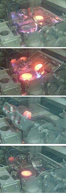
A glass "bead" specimen for XRF analysis being cast at around 1100 °C in a Herzog automated fusion machine in a cement plant quality control laboratory. 1 (top): fusing, 2: preheating the mould, 3: pouring the melt, 4: cooling the "bead"

Extracting analytical results

At first sight, the translation of X-ray photon count-rates into elemental concentrations would appear to be straightforward: WDX separates the X-ray lines efficiently, and the rate of generation of secondary photons is proportional to the element concentration. However, the number of photons leaving the sample is also affected by the physical properties of the sample: so-called "matrix effects". These fall broadly into three categories:
  • X-ray absorption
  • X-ray enhancement
  • Sample macroscopic effects
All elements absorb X-rays to some extent. Each element has a characteristic absorption spectrum which consists of a "saw-tooth" succession of fringes, each step-change of which has wavelength close to an emission line of the element. Absorption attenuates the secondary X-rays leaving the sample. For example, the mass absorption coefficient of silicon at the wavelength of the aluminium Kα line is 50 m²/kg, whereas that of iron is 377 m²/kg. This means that a given concentration of aluminium in a matrix of iron gives only one seventh of the count rate compared with the same concentration of aluminium in a silicon matrix. Fortunately, mass absorption coefficients are well known and can be calculated. However, to calculate the absorption for a multi-element sample, the composition must be known. For analysis of an unknown sample, an iterative procedure is therefore used. It will be noted that, to derive the mass absorption accurately, data for the concentration of elements not measured by XRF may be needed, and various strategies are employed to estimate these. As an example, in cement analysis, the concentration of oxygen (which is not measured) is calculated by assuming that all other elements are present as standard oxides.

Enhancement occurs where the secondary X-rays emitted by a heavier element are sufficiently energetic to stimulate additional secondary emission from a lighter element. This phenomenon can also be modelled, and corrections can be made provided that the full matrix composition can be deduced.

Sample macroscopic effects consist of effects of inhomogeneities of the sample, and unrepresentative conditions at its surface. Samples are ideally homogeneous and isotropic, but they often deviate from this ideal. Mixtures of multiple crystalline components in mineral powders can result in absorption effects that deviate from those calculable from theory. When a powder is pressed into a tablet, the finer minerals concentrate at the surface. Spherical grains tend to migrate to the surface more than do angular grains. In machined metals, the softer components of an alloy tend to smear across the surface. Considerable care and ingenuity are required to minimize these effects. Because they are artifacts of the method of sample preparation, these effects can not be compensated by theoretical corrections, and must be "calibrated in". This means that the calibration materials and the unknowns must be compositionally and mechanically similar, and a given calibration is applicable only to a limited range of materials. Glasses most closely approach the ideal of homogeneity and isotropy, and for accurate work, minerals are usually prepared by dissolving them in a borate glass, and casting them into a flat disc or "bead". Prepared in this form, a virtually universal calibration is applicable. 

Further corrections that are often employed include background correction and line overlap correction. The background signal in an XRF spectrum derives primarily from scattering of primary beam photons by the sample surface. Scattering varies with the sample mass absorption, being greatest when mean atomic number is low. When measuring trace amounts of an element, or when measuring on a variable light matrix, background correction becomes necessary. This is really only feasible on a sequential spectrometer. Line overlap is a common problem, bearing in mind that the spectrum of a complex mineral can contain several hundred measurable lines. Sometimes it can be overcome by measuring a less-intense, but overlap-free line, but in certain instances a correction is inevitable. For instance, the Kα is the only usable line for measuring sodium, and it overlaps the zinc Lβ (L2-M4) line. Thus zinc, if present, must be analysed in order to properly correct the sodium value.

Other spectroscopic methods using the same principle

It is also possible to create a characteristic secondary X-ray emission using other incident radiation to excite the sample:
When radiated by an X-ray beam, the sample also emits other radiations that can be used for analysis:
The de-excitation also ejects Auger electrons, but Auger electron spectroscopy (AES) normally uses an electron beam as the probe. 

Confocal microscopy X-ray fluorescence imaging is a newer technique that allows control over depth, in addition to horizontal and vertical aiming, for example, when analysing buried layers in a painting.

Instrument qualification

A 2001 review, addresses the application of portable instrumentation from QA/QC perspectives. It provides a guide to the development of a set of SOPs if regulatory compliance guidelines are not available.

Operator (computer programming)

From Wikipedia, the free encyclopedia https://en.wikipedia.org/wiki/Operator_(computer_programmin...