Nuclear weapons tests are experiments carried out to determine the performance, yield, and effects of nuclear weapons. Testing nuclear weapons offers practical information about how the weapons function, how detonations are affected by different conditions, and how personnel, structures, and equipment are affected when subjected to nuclear explosions. However, nuclear testing has often been used as an indicator of scientific and military strength. Many tests have been overtly political in their intention; most nuclear weapons states publicly declared their nuclear status through a nuclear test.
The first nuclear device was detonated as a test by the United States at the Trinity site in New Mexico on July 16, 1945, with a yield approximately equivalent to 20 kilotons of TNT. The first thermonuclear weapon technology test of an engineered device, codenamed "Ivy Mike", was tested at the Enewetak Atoll in the Marshall Islands on November 1, 1952 (local date), also by the United States. The largest nuclear weapon ever tested was the "Tsar Bomba" of the Soviet Union at Novaya Zemlya on October 30, 1961, with the largest yield ever seen, an estimated 50–58 megatons.
In 1963, three (UK, US, Soviet Union) of the then four nuclear states and many non-nuclear states signed the Limited Test Ban Treaty, pledging to refrain from testing nuclear weapons in the atmosphere, underwater, or in outer space. The treaty permitted underground nuclear testing. France continued atmospheric testing until 1974, and China continued until 1980. Neither has signed the treaty.
Underground tests conducted by the Soviet Union continued until 1990, the United Kingdom until 1991, the United States until 1992, and both China and France until 1996. In signing the Comprehensive Nuclear-Test-Ban Treaty in 1996, these countries pledged to discontinue all nuclear testing; the treaty has not yet entered into force because of its failure to be ratified by eight countries. Non-signatories India and Pakistan last tested nuclear weapons in 1998. North Korea conducted nuclear tests in 2006, 2009, 2013, 2016, and 2017. The most recent confirmed nuclear test occurred in September 2017 in North Korea.
Types
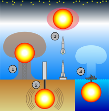
Nuclear weapons tests have historically been divided into four categories reflecting the medium or location of the test.
- Atmospheric testing designates explosions that take place in the atmosphere. Generally, these have occurred as devices detonated on towers, balloons, barges, or islands, or dropped from airplanes, and also those only buried far enough to intentionally create a surface-breaking crater. The United States, the Soviet Union, and China have all conducted tests involving explosions of missile-launched bombs (See List of nuclear weapons tests#Tests of live warheads on rockets). Nuclear explosions close enough to the ground to draw dirt and debris into their mushroom cloud can generate large amounts of nuclear fallout due to irradiation of the debris. This definition of atmospheric is used in the Limited Test Ban Treaty, which banned this class of testing along with exoatmospheric and underwater.
- Underground testing refers to nuclear tests conducted under the surface of the earth, at varying depths. Underground nuclear testing made up the majority of nuclear tests by the United States and the Soviet Union during the Cold War; other forms of nuclear testing were banned by the Limited Test Ban Treaty
in 1963. True underground tests are intended to be fully contained and
emit a negligible amount of fallout. Unfortunately these nuclear tests
do occasionally "vent" to the surface, producing from nearly none to
considerable amounts of radioactive debris as a consequence. Underground
testing, almost by definition, causes seismic activity of a magnitude that depends on the yield of the nuclear device and the composition of the medium in which it is detonated, and generally creates a subsidence crater. In 1976, the United States and the USSR agreed to limit the maximum yield of underground tests to 150 kt with the Threshold Test Ban Treaty.
Underground testing also falls into two physical categories: tunnel tests in generally horizontal tunnel drifts, and shaft tests in vertically drilled holes. - Exoatmospheric testing refers to nuclear tests conducted above the atmosphere. The test devices are lifted on rockets. These high-altitude nuclear explosions can generate a nuclear electromagnetic pulse (NEMP) when they occur in the ionosphere, and charged particles resulting from the blast can cross hemispheres following geomagnetic lines of force to create an auroral display.
- Underwater testing involves nuclear devices being detonated underwater, usually moored to a ship or a barge (which is subsequently destroyed by the explosion). Tests of this nature have usually been conducted to evaluate the effects of nuclear weapons against naval vessels (such as in Operation Crossroads), or to evaluate potential sea-based nuclear weapons (such as nuclear torpedoes or depth charges). Underwater tests close to the surface can disperse large amounts of radioactive particles in water and steam, contaminating nearby ships or structures, though they generally do not create fallout other than very locally to the explosion.
Salvo tests
Another way to classify nuclear tests is by the number of explosions that constitute the test. The treaty definition of a salvo test is:
In conformity with treaties between the United States and the Soviet Union, a salvo is defined, for multiple explosions for peaceful purposes, as two or more separate explosions where a period of time between successive individual explosions does not exceed 5 seconds and where the burial points of all explosive devices can be connected by segments of straight lines, each of them connecting two burial points, and the total length does not exceed 40 kilometers. For nuclear weapon tests, a salvo is defined as two or more underground nuclear explosions conducted at a test site within an area delineated by a circle having a diameter of two kilometers and conducted within a total period of time of 0.1 seconds.
The USSR has exploded up to eight devices in a single salvo test; Pakistan's second and last official test exploded four different devices. Almost all lists in the literature are lists of tests; in the lists in Wikipedia (for example, Operation Cresset has separate items for Cremino and Caerphilly, which together constitute a single test), the lists are of explosions.
Purpose
Separately from these designations, nuclear tests are also often categorized by the purpose of the test itself.
- Weapons-related tests are designed to garner information about how (and if) the weapons themselves work. Some serve to develop and validate a specific weapon type. Others test experimental concepts or are physics experiments meant to gain fundamental knowledge of the processes and materials involved in nuclear detonations.
- Weapons effects tests are designed to gain information about the effects of the weapons on structures, equipment, organisms, and the environment. They are mainly used to assess and improve survivability to nuclear explosions in civilian and military contexts, tailor weapons to their targets, and develop the tactics of nuclear warfare.
- Safety experiments are designed to study the behavior of weapons in simulated accident scenarios. In particular, they are used to verify that a (significant) nuclear detonation cannot happen by accident. They include one-point safety tests and simulations of storage and transportation accidents.
- Nuclear test detection experiments are designed to improve the capabilities to detect, locate, and identify nuclear detonations, in particular, to monitor compliance with test-ban treaties. In the United States these tests are associated with Operation Vela Uniform before the Comprehensive Test Ban Treaty stopped all nuclear testing among signatories.
- Peaceful nuclear explosions were conducted to investigate non-military applications of nuclear explosives. In the United States, these were performed under the umbrella name of Operation Plowshare.
Aside from these technical considerations, tests have been conducted for political and training purposes, and can often serve multiple purposes.
Alternatives to full-scale testing

Hydronuclear tests study nuclear materials under the conditions of explosive shock compression. They can create subcritical conditions, or supercritical conditions with yields ranging from negligible all the way up to a substantial fraction of full weapon yield.
Critical mass experiments determine the quantity of fissile material required for criticality with a variety of fissile material compositions, densities, shapes, and reflectors. They can be subcritical or supercritical, in which case significant radiation fluxes can be produced. This type of test has resulted in several criticality accidents.
Subcritical (or cold) tests are any type of tests involving nuclear materials and possibly high explosives (like those mentioned above) that purposely result in no yield. The name refers to the lack of creation of a critical mass of fissile material. They are the only type of tests allowed under the interpretation of the Comprehensive Nuclear-Test-Ban Treaty tacitly agreed to by the major atomic powers. Subcritical tests continue to be performed by the United States, Russia, and the People's Republic of China, at least.
Subcritical tests executed by the United States include:
| Name | Date Time (UT) | Location | Elevation + Height | Notes |
|---|---|---|---|---|
| A series of 50 tests | January 1, 1960 | Los Alamos National Lab Test Area 49 35.82289°N 106.30216°W | 2,183 metres (7,162 ft) and 20 metres (66 ft) | Series of 50 tests during US/USSR joint nuclear test ban. |
| Odyssey |
|
NTS Area U1a 37.01139°N 116.05983°W | 1,222 metres (4,009 ft) and 190 metres (620 ft) |
|
| Trumpet |
|
NTS Area U1a-102D 37.01099°N 116.05848°W | 1,222 metres (4,009 ft) and 190 metres (620 ft) |
|
| Kismet | March 1, 1995 | NTS Area U1a 37.01139°N 116.05983°W | 1,222 metres (4,009 ft) and 293 metres (961 ft) | Kismet was a proof of concept for modern hydronuclear tests; it did not contain any SNM (Special Nuclear Material—plutonium or uranium). |
| Rebound | July 2, 1997 10:—:— | NTS Area U1a 37.01139°N 116.05983°W | 1,222 metres (4,009 ft) and 293 metres (961 ft) | Provided information on the behavior of new plutonium alloys compressed by high-pressure shock waves; same as Stagecoach but for the age of the alloys. |
| Holog | September 18, 1997 | NTS Area U1a.101A 37.01036°N 116.05888°W | 1,222 metres (4,009 ft) and 290 metres (950 ft) | Holog and Clarinet may have switched locations. |
| Stagecoach | March 25, 1998 | NTS Area U1a 37.01139°N 116.05983°W | 1,222 metres (4,009 ft) and 290 metres (950 ft) | Provided information on the behavior of aged (up to 40 years) plutonium alloys compressed by high-pressure shock waves. |
| Bagpipe | September 26, 1998 | NTS Area U1a.101B 37.01021°N 116.05886°W | 1,222 metres (4,009 ft) and 290 metres (950 ft) |
|
| Cimarron | December 11, 1998 | NTS Area U1a 37.01139°N 116.05983°W | 1,222 metres (4,009 ft) and 290 metres (950 ft) | Plutonium surface ejecta studies. |
| Clarinet | February 9, 1999 | NTS Area U1a.101C 37.01003°N 116.05898°W | 1,222 metres (4,009 ft) and 290 metres (950 ft) | Holog and Clarinet may have switched places on the map. |
| Oboe | September 30, 1999 | NTS Area U1a.102C 37.01095°N 116.05877°W | 1,222 metres (4,009 ft) and 290 metres (950 ft) |
|
| Oboe 2 | November 9, 1999 | NTS Area U1a.102C 37.01095°N 116.05877°W | 1,222 metres (4,009 ft) and 290 metres (950 ft) |
|
| Oboe 3 | February 3, 2000 | NTS Area U1a.102C 37.01095°N 116.05877°W | 1,222 metres (4,009 ft) and 290 metres (950 ft) |
|
| Thoroughbred | March 22, 2000 | NTS Area U1a 37.01139°N 116.05983°W | 1,222 metres (4,009 ft) and 290 metres (950 ft) | Plutonium surface ejecta studies, followup to Cimarron. |
| Oboe 4 | April 6, 2000 | NTS Area U1a.102C 37.01095°N 116.05877°W | 1,222 metres (4,009 ft) and 290 metres (950 ft) |
|
| Oboe 5 | August 18, 2000 | NTS Area U1a.102C 37.01095°N 116.05877°W | 1,222 metres (4,009 ft) and 290 metres (950 ft) |
|
| Oboe 6 | December 14, 2000 | NTS Area U1a.102C 37.01095°N 116.05877°W | 1,222 metres (4,009 ft) and 290 metres (950 ft) |
|
| Oboe 8 | September 26, 2001 | NTS Area U1a.102C 37.01095°N 116.05877°W | 1,222 metres (4,009 ft) and 290 metres (950 ft) |
|
| Oboe 7 | December 13, 2001 | NTS Area U1a.102C 37.01095°N 116.05877°W | 1,222 metres (4,009 ft) and 290 metres (950 ft) |
|
| Oboe 9 | June 7, 2002 21:46:— | NTS Area U1a.102C 37.01095°N 116.05877°W | 1,222 metres (4,009 ft) and 290 metres (950 ft) |
|
| Mario | August 29, 2002 19:00:— | NTS Area U1a 37.01139°N 116.05983°W | 1,222 metres (4,009 ft) and 290 metres (950 ft) | Plutonium surface studies (optical analysis of spall). Used wrought plutonium from Rocky Flats. |
| Rocco | September 26, 2002 19:00:— | NTS Area U1a 37.01139°N 116.05983°W | 1,222 metres (4,009 ft) and 290 metres (950 ft) | Plutonium surface studies (optical analysis of spall), followup to Mario. Used cast plutonium from Los Alamos. |
| Piano | September 19, 2003 20:44:— | NTS Area U1a.102C 37.01095°N 116.05877°W | 1,222 metres (4,009 ft) and 290 metres (950 ft) |
|
| Armando | May 25, 2004 | NTS Area U1a 37.01139°N 116.05983°W | 1,222 metres (4,009 ft) and 290 metres (950 ft) | Plutonium spall measurements using x-ray analysis. |
| Step Wedge | April 1, 2005 | NTS Area U1a 37.01139°N 116.05983°W | 1,222 metres (4,009 ft) and 190 metres (620 ft) | April–May 2005, a series of mini-hydronuclear experiments interpreting Armando results. |
| Unicorn | August 31, 2006 01:00:— | NTS Area U6c 36.98663°N 116.0439°W | 1,222 metres (4,009 ft) and 190 metres (620 ft) | "...confirm nuclear performance of the W88 warhead with a newly-manufactured pit." Early pit studies. |
| Thermos | January 1, 2007 | NTS Area U1a 37.01139°N 116.05983°W | 1,222 metres (4,009 ft) and 190 metres (620 ft) | February 6 – May 3, 2007, 12 mini-hydronuclear experiments in thermos-sized flasks. |
| Bacchus | September 16, 2010 | NTS Area U1a.05? 37.01139°N 116.05983°W | 1,222 metres (4,009 ft) and 190 metres (620 ft) |
|
| Barolo A | December 1, 2010 | NTS Area U1a.05? 37.01139°N 116.05983°W | 1,222 metres (4,009 ft) and 190 metres (620 ft) |
|
| Barolo B | February 2, 2011 | NTS Area U1a.05? 37.01139°N 116.05983°W | 1,222 metres (4,009 ft) and 190 metres (620 ft) |
|
| Castor | September 1, 2012 | NTS Area U1a 37.01139°N 116.05983°W | 1,222 metres (4,009 ft) and 190 metres (620 ft) | Not even a subcritical, contained no plutonium; a dress rehearsal for Pollux. |
| Pollux | December 5, 2012 | NTS Area U1a 37.01139°N 116.05983°W | 1,222 metres (4,009 ft) and 190 metres (620 ft) | A subcritical test with a scaled-down warhead mockup. |
| Leda | June 15, 2014 | NTS Area U1a 37.01139°N 116.05983°W | 1,222 metres (4,009 ft) and 190 metres (620 ft) | Like Castor, the plutonium was replaced by a surrogate; this is a dress rehearsal for the later Lydia. The target was a weapons pit mock-up. |
| Lydia | ??-??-2015 | NTS Area U1a 37.01139°N 116.05983°W | 1,222 metres (4,009 ft) and 190 metres (620 ft) | Expected to be a plutonium subcritical test with a scaled-down warhead mockup. |
| Vega | December 13, 2017 | Nevada test site |
|
Plutonium subcritical test with a scaled down warhead mockup. |
| Ediza | February 13, 2019 | NTS Area U1a 37.01139°N 116.05983°W |
|
Plutonium subcritical test designed to confirm supercomputer simulations for stockpile safety. |
| Nightshade A | November 2020 | Nevada test site |
|
Plutonium subcritical test designed to measure ejecta emission. |
History
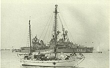
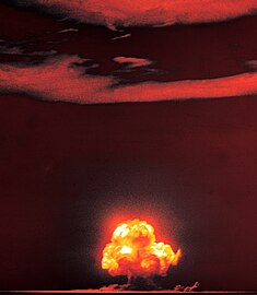
The first atomic weapons test was conducted near Alamogordo, New Mexico, on July 16, 1945, during the Manhattan Project, and given the codename "Trinity". The test was originally to confirm that the implosion-type nuclear weapon design was feasible, and to give an idea of what the actual size and effects of a nuclear explosion would be before they were used in combat against Japan. While the test gave a good approximation of many of the explosion's effects, it did not give an appreciable understanding of nuclear fallout, which was not well understood by the project scientists until well after the atomic bombings of Hiroshima and Nagasaki.
The United States conducted six atomic tests before the Soviet Union developed their first atomic bomb (RDS-1) and tested it on August 29, 1949. Neither country had very many atomic weapons to spare at first, and so testing was relatively infrequent (when the U.S. used two weapons for Operation Crossroads in 1946, they were detonating over 20% of their current arsenal). However, by the 1950s the United States had established a dedicated test site on its own territory (Nevada Test Site) and was also using a site in the Marshall Islands (Pacific Proving Grounds) for extensive atomic and nuclear testing.
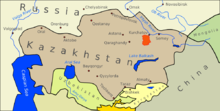
The early tests were used primarily to discern the military effects of atomic weapons (Crossroads had involved the effect of atomic weapons on a navy, and how they functioned underwater) and to test new weapon designs. During the 1950s, these included new hydrogen bomb designs, which were tested in the Pacific, and also new and improved fission weapon designs. The Soviet Union also began testing on a limited scale, primarily in Kazakhstan. During the later phases of the Cold War, though, both countries developed accelerated testing programs, testing many hundreds of bombs over the last half of the 20th century.

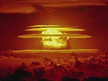
Atomic and nuclear tests can involve many hazards. Some of these were illustrated in the U.S. Castle Bravo test in 1954. The weapon design tested was a new form of hydrogen bomb, and the scientists underestimated how vigorously some of the weapon materials would react. As a result, the explosion—with a yield of 15 Mt—was over twice what was predicted. Aside from this problem, the weapon also generated a large amount of radioactive nuclear fallout, more than had been anticipated, and a change in the weather pattern caused the fallout to spread in a direction not cleared in advance. The fallout plume spread high levels of radiation for over 100 miles (160 km), contaminating a number of populated islands in nearby atoll formations. Though they were soon evacuated, many of the islands' inhabitants suffered from radiation burns and later from other effects such as increased cancer rate and birth defects, as did the crew of the Japanese fishing boat Daigo Fukuryū Maru. One crewman died from radiation sickness after returning to port, and it was feared that the radioactive fish they had been carrying had made it into the Japanese food supply.

Castle Bravo was the worst U.S. nuclear accident, but many of its component problems—unpredictably large yields, changing weather patterns, unexpected fallout contamination of populations and the food supply—occurred during other atmospheric nuclear weapons tests by other countries as well. Concerns over worldwide fallout rates eventually led to the Partial Test Ban Treaty in 1963, which limited signatories to underground testing. Not all countries stopped atmospheric testing, but because the United States and the Soviet Union were responsible for roughly 86% of all nuclear tests, their compliance cut the overall level substantially. France continued atmospheric testing until 1974, and China until 1980.
A tacit moratorium on testing was in effect from 1958 to 1961 and ended with a series of Soviet tests in late 1961, including the Tsar Bomba, the largest nuclear weapon ever tested. The United States responded in 1962 with Operation Dominic, involving dozens of tests, including the explosion of a missile launched from a submarine.
Almost all new nuclear powers have announced their possession of nuclear weapons with a nuclear test. The only acknowledged nuclear power that claims never to have conducted a test was South Africa (although see Vela incident), which has since dismantled all of its weapons. Israel is widely thought to possess a sizable nuclear arsenal, though it has never tested, unless they were involved in Vela. Experts disagree on whether states can have reliable nuclear arsenals—especially ones using advanced warhead designs, such as hydrogen bombs and miniaturized weapons—without testing, though all agree that it is very unlikely to develop significant nuclear innovations without testing. One other approach is to use supercomputers to conduct "virtual" testing, but codes need to be validated against test data.
There have been many attempts to limit the number and size of nuclear tests; the most far-reaching is the Comprehensive Test Ban Treaty of 1996, which has not, as of 2013, been ratified by eight of the "Annex 2 countries" required for it to take effect, including the United States. Nuclear testing has since become a controversial issue in the United States, with a number of politicians saying that future testing might be necessary to maintain the aging warheads from the Cold War. Because nuclear testing is seen as furthering nuclear arms development, many are opposed to future testing as an acceleration of the arms race.
In total nuclear test megatonnage, from 1945 to 1992, 520 atmospheric nuclear explosions (including eight underwater) were conducted with a total yield of 545 megatons, with a peak occurring in 1961–1962, when 340 megatons were detonated in the atmosphere by the United States and Soviet Union, while the estimated number of underground nuclear tests conducted in the period from 1957 to 1992 was 1,352 explosions with a total yield of 90 Mt.
-
The first atomic test, "Trinity", took place on July 16, 1945.
-
The Sedan test of 1962 was an experiment by the United States in using nuclear weapons to excavate large amounts of earth.
-
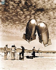
Kytoon balloons were used on Indian Springs Air Force Base, Nevada, April 20, 1952 to get exact weather information during atomic test periods.
Yield
The yields of atomic bombs and thermonuclear are typically measured in different amounts. Thermonuclear bombs can be hundreds or thousands of times stronger than their atomic counterparts. Due to this, thermonuclear bombs' yields are usually expressed in megatons which is about the equivalent of 1,000,000 tons of TNT. In contrast, atomic bombs' yields are typically measured in kilotons, or about 1,000 tons of TNT.
In US context, it was decided during the Manhattan Project that yield measured in tons of TNT equivalent could be imprecise. This comes from the range of experimental values of the energy content of TNT, ranging from 900 to 1,100 calories per gram (3,800 to 4,600 kJ/g). There is also the issue of which ton to use, as short tons, long tons, and metric tonnes all have different values. It was therefore decided that one kiloton would be equivalent to 1.0×10¹² calories (4.2×10¹² kJ).
Nuclear testing by country


The nuclear powers have conducted more than 2,000 nuclear test explosions (numbers are approximate, as some test results have been disputed):
 United States: 1,054 tests by official count (involving at least 1,149 devices). 219 were atmospheric tests as defined by the CTBT. These tests include 904 at the Nevada Test Site, 106 at the Pacific Proving Grounds and other locations in the Pacific, 3 in the South Atlantic Ocean, and 17 other tests taking place in Amchitka Alaska, Colorado, Mississippi, New Mexico and Nevada outside the NNSS (see Nuclear weapons and the United States
for details). 24 tests are classified as British tests held at the NTS.
There were 35 Plowshare detonations and 7 Vela Uniform tests; 88 tests
were safety experiments and 4 were transportation/storage tests. Motion pictures were made of the explosions, later used to validate computer simulation predictions of explosions. United States' table data.
 Soviet Union: 715 tests (involving 969 devices) by official count, plus 13 unnumbered test failures. Most were at their Southern Test Area at Semipalatinsk Test Site and the Northern Test Area at Novaya Zemlya. Others include rocket tests and peaceful-use explosions at various sites in Russia, Kazakhstan, Turkmenistan, Uzbekistan and Ukraine. Soviet Union's table data.
 United Kingdom: 45 tests, of which 12 were in Australian territory, including three at the Montebello Islands and nine in mainland South Australia at Maralinga and Emu Field, 9 at Christmas Island (Kiritimati) in the Pacific Ocean, plus 24 in the United States at the Nevada Test Site as part of joint test series). 43 safety tests (the Vixen series) are not included in that number, though safety experiments by other countries are. The United Kingdom's summary table.
 France: 210 tests by official count (50 atmospheric, 160 underground), four atomic atmospheric tests at C.E.S.M. near Reggane, 13 atomic underground tests at C.E.M.O. near In Ekker in the French Algerian Sahara, and nuclear atmospheric and underground tests at and around Fangataufa and Moruroa Atolls in French Polynesia.
Four of the In Ekker tests are counted as peaceful use, as they were
reported as part of the CET's APEX (Application pacifique des
expérimentations nucléaires), and given alternate names. France's summary table.
 China: 45 tests (23 atmospheric and 22 underground), at Lop Nur Nuclear Weapons Test Base, in Malan, Xinjiang There are two additional unnumbered failed tests. China's summary table.
 India: Six underground explosions (including the first one in 1974), at Pokhran. India's summary table.
 Pakistan: Six underground explosions at Ras Koh Hills and the Chagai District. Pakistan's summary table.
 North Korea: North Korea is the only country in the world that still tests nuclear weapons, and their tests have caused escalating tensions between them and the United States. Their most recent nuclear test was on September 3, 2017. North Korea's summary table
There may also have been at least three alleged but unacknowledged nuclear explosions (see list of alleged nuclear tests) including the Vela incident.
From the first nuclear test in 1945 until tests by Pakistan in 1998, there was never a period of more than 22 months with no nuclear testing. June 1998 to October 2006 was the longest period since 1945 with no acknowledged nuclear tests.
A summary table of all the nuclear testing that has happened since 1945 is here: Worldwide nuclear testing counts and summary.

Treaties against testing
There are many existing anti-nuclear explosion treaties, notably the Partial Nuclear Test Ban Treaty and the Comprehensive Nuclear Test Ban Treaty. These treaties were proposed in response to growing international concerns about environmental damage among other risks. Nuclear testing involving humans also contributed to the formation of these treaties. Examples can be seen in the following articles:
The Partial Nuclear Test Ban treaty makes it illegal to detonate any nuclear explosion anywhere except underground, in order to reduce atmospheric fallout. Most countries have signed and ratified the Partial Nuclear Test Ban, which went into effect in October 1963. Of the nuclear states, France, China, and North Korea have never signed the Partial Nuclear Test Ban Treaty.
The 1996 Comprehensive Nuclear-Test-Ban Treaty (CTBT) bans all nuclear explosions everywhere, including underground. For that purpose, the Preparatory Commission of the Comprehensive Nuclear-Test-Ban Treaty Organization is building an international monitoring system with 337 facilities located all over the globe. 85% of these facilities are already operational. As of May 2012, the CTBT has been signed by 183 States, of which 157 have also ratified. However, for the Treaty to enter into force it needs to be ratified by 44 specific nuclear technology-holder countries. These "Annex 2 States" participated in the negotiations on the CTBT between 1994 and 1996 and possessed nuclear power or research reactors at that time. The ratification of eight Annex 2 states is still missing: China, Egypt, Iran, Israel and the United States have signed but not ratified the Treaty; India, North Korea and Pakistan have not signed it.
The following is a list of the treaties applicable to nuclear testing:
| Name | Agreement date | In force date | In effect today? | Notes |
|---|---|---|---|---|
| Unilateral USSR ban | March 31, 1958 | March 31, 1958 | no | USSR unilaterally stops testing provided the West does as well. |
| Bilateral testing ban | August 2, 1958 | October 31, 1958 | no | USA agrees; ban begins on 31 October 1958, 3 November 1958 for the Soviets, and lasts until abrogated by a USSR test on 1 September 1961. |
| Antarctic Treaty System | December 1, 1959 | June 23, 1961 | yes | Bans testing of all kinds in Antarctica. |
| Partial Nuclear Test Ban Treaty (PTBT) | August 5, 1963 | October 10, 1963 | yes | Ban on all but underground testing. |
| Outer Space Treaty | January 27, 1967 | October 10, 1967 | yes | Bans testing on the moon and other celestial bodies. |
| Treaty of Tlatelolco | February 14, 1967 | April 22, 1968 | yes | Bans testing in South America and the Caribbean Sea Islands. |
| Nuclear Non-proliferation Treaty | January 1, 1968 | March 5, 1970 | yes | Bans the proliferation of nuclear technology to non-nuclear nations. |
| Seabed Arms Control Treaty | February 11, 1971 | May 18, 1972 | yes | Bans emplacement of nuclear weapons on the ocean floor outside territorial waters. |
| Strategic Arms Limitation Treaty (SALT I) | January 1, 1972 |
|
no | A five-year ban on installing launchers. |
| Anti-Ballistic Missile Treaty | May 26, 1972 | August 3, 1972 | no | Restricts ABM development; additional protocol added in 1974; abrogated by the US in 2002. |
| Agreement on the Prevention of Nuclear War | June 22, 1973 | June 22, 1973 | yes | Promises to make all efforts to promote security and peace. |
| Threshold Test Ban Treaty | July 1, 1974 | December 11, 1990 | yes | Prohibits higher than 150 kt for underground testing. |
| Peaceful Nuclear Explosions Treaty (PNET) | January 1, 1976 | December 11, 1990 | yes | Prohibits higher than 150 kt, or 1500kt in aggregate, testing for peaceful purposes. |
| Moon Treaty | January 1, 1979 | January 1, 1984 | no | Bans use and emplacement of nuclear weapons on the moon and other celestial bodies. |
| Strategic Arms Limitations Treaty (SALT II) | June 18, 1979 |
|
no | Limits strategic arms. Kept but not ratified by the US, abrogated in 1986. |
| Treaty of Rarotonga | August 6, 1985 |
|
? | Bans nuclear weapons in South Pacific Ocean and islands. US never ratified. |
| Intermediate Range Nuclear Forces Treaty (INF) | December 8, 1987 | June 1, 1988 | no | Eliminated Intermediate Range Ballistic Missiles (IRBMs). Implemented by 1 June 1991. Both sides alleged the other was in violation of the treaty. Expired following U.S. withdrawal, 2 August 2019. |
| Treaty on Conventional Armed Forces in Europe | November 19, 1990 | July 17, 1992 | yes | Bans categories of weapons, including conventional, from Europe. Russia notified signatories of intent to suspend, 14 July 2007. |
| Strategic Arms Reduction Treaty I (START I) | July 31, 1991 | December 5, 1994 | no | 35-40% reduction in ICBMs with verification. Treaty expired 5 December 2009, renewed (see below). |
| Treaty on Open Skies | March 24, 1992 | January 1, 2002 | yes | Allows for unencumbered surveillance over all signatories. |
| US unilateral testing moratorium | October 2, 1992 | October 2, 1992 | no | George. H. W. Bush declares unilateral ban on nuclear testing. Extended several times, not yet abrogated. |
| Strategic Arms Reduction Treaty (START II) | January 3, 1993 | January 1, 2002 | no | Deep reductions in ICBMs. Abrogated by Russia in 2002 in retaliation of US abrogation of ABM Treaty. |
| Southeast Asian Nuclear-Weapon-Free Zone Treaty (Treaty of Bangkok) | December 15, 1995 | March 28, 1997 | yes | Bans nuclear weapons from southeast Asia. |
| African Nuclear Weapon Free Zone Treaty (Pelindaba Treaty) | January 1, 1996 | July 16, 2009 | yes | Bans nuclear weapons in Africa. |
| Comprehensive Nuclear Test Ban Treaty (CTBT) | September 10, 1996 |
|
yes (effectively) | Bans all nuclear testing, peaceful and otherwise. Strong detection and verification mechanism (CTBTO). US has signed and adheres to the treaty, though has not ratified it. |
| Treaty on Strategic Offensive Reductions (SORT, Treaty of Moscow) | May 24, 2002 | June 1, 2003 | no | Reduces warheads to 1700–2200 in ten years. Expired, replaced by START II. |
| START I treaty renewal | April 8, 2010 | January 26, 2011 | yes | Same provisions as START I. |
Compensation for victims
Over 500 atmospheric nuclear weapons tests were conducted at various sites around the world from 1945 to 1980. As public awareness and concern mounted over the possible health hazards associated with exposure to the nuclear fallout, various studies were done to assess the extent of the hazard. A Centers for Disease Control and Prevention/ National Cancer Institute study claims that nuclear fallout might have led to approximately 11,000 excess deaths, most caused by thyroid cancer linked to exposure to iodine-131.
- United States: Prior to March 2009, the U.S. was the only nation to compensate nuclear test victims. Since the Radiation Exposure Compensation Act of 1990, more than $1.38 billion in compensation has been approved. The money is going to people who took part in the tests, notably at the Nevada Test Site, and to others exposed to the radiation. As of 2017, the U.S. government refused to pay for the medical care of troops who associate their health problems with the construction of Runit Dome in the Marshall Islands.
- France: In March 2009, the French Government offered to compensate victims for the first time and legislation is being drafted which would allow payments to people who suffered health problems related to the tests. The payouts would be available to victims' descendants and would include Algerians, who were exposed to nuclear testing in the Sahara in 1960. However, victims say the eligibility requirements for compensation are too narrow.
- United Kingdom: There is no formal British government compensation program. However, nearly 1,000 veterans of Christmas Island nuclear tests in the 1950s are engaged in legal action against the Ministry of Defense for negligence. They say they suffered health problems and were not warned of potential dangers before the experiments.
- Russia: Decades later, Russia offered compensation to veterans who were part of the 1954 Totsk test. However, there was no compensation to civilians sickened by the Totsk test. Anti-nuclear groups say there has been no government compensation for other nuclear tests.
- China: China has undertaken highly secretive atomic tests in remote deserts in a Central Asian border province. Anti-nuclear activists say there is no known government program for compensating victims.
Milestone nuclear explosions
The following list is of milestone nuclear explosions. In addition to the atomic bombings of Hiroshima and Nagasaki, the first nuclear test of a given weapon type for a country is included, as well as tests that were otherwise notable (such as the largest test ever). All yields (explosive power) are given in their estimated energy equivalents in kilotons of TNT (see TNT equivalent). Putative tests (like Vela incident) have not been included.
| Date | Name | Yield (kt)
|
Country | Significance |
|---|---|---|---|---|
| July 16, 1945 | Trinity | 18–20 | United States | First fission-device test, first plutonium implosion detonation. |
| August 6, 1945 | Little Boy | 12–18 | United States | Bombing of Hiroshima, Japan, first detonation of a uranium gun-type device, first use of a nuclear device in combat. |
| August 9, 1945 | Fat Man | 18–23 | United States | Bombing of Nagasaki, Japan, second detonation of a plutonium implosion device (the first being the Trinity Test), second and last use of a nuclear device in combat. |
| August 29, 1949 | RDS-1 | 22 | Soviet Union | First fission-weapon test by the Soviet Union. |
| May 8, 1951 | George | 225 | United States | First boosted nuclear weapon test, first weapon test to employ fusion in any measure. |
| October 3, 1952 | Hurricane | 25 | United Kingdom | First fission weapon test by the United Kingdom. |
| November 1, 1952 | Ivy Mike | 10,400 | United States | First "staged" thermonuclear weapon, with cryogenic fusion fuel, primarily a test device and not weaponized. |
| November 16, 1952 | Ivy King | 500 | United States | Largest pure-fission weapon ever tested. |
| August 12, 1953 | RDS-6s | 400 | Soviet Union | First fusion-weapon test by the Soviet Union (not "staged"). |
| March 1, 1954 | Castle Bravo | 15,000 | United States | First "staged" thermonuclear weapon using dry fusion fuel. A serious nuclear fallout accident occurred. Largest nuclear detonation conducted by United States. |
| November 22, 1955 | RDS-37 | 1,600 | Soviet Union | First "staged" thermonuclear weapon test by the Soviet Union (deployable). |
| May 31, 1957 | Orange Herald | 720 | United Kingdom | Largest boosted fission weapon ever tested. Intended as a fallback "in megaton range" in case British thermonuclear development failed. |
| November 8, 1957 | Grapple X | 1,800 | United Kingdom | First (successful) "staged" thermonuclear weapon test by the United Kingdom |
| February 13, 1960 | Gerboise Bleue | 70 | France | First fission weapon test by France. |
| October 31, 1961 | Tsar Bomba | 50,000 | Soviet Union | Largest thermonuclear weapon ever tested—scaled down from its initial 100 Mt design by 50%. |
| October 16, 1964 | 596 | 22 | China | First fission-weapon test by the People's Republic of China. |
| June 17, 1967 | Test No. 6 | 3,300 | China | First "staged" thermonuclear weapon test by the People's Republic of China. |
| August 24, 1968 | Canopus | 2,600 | France | First "staged" thermonuclear weapon test by France |
| May 18, 1974 | Smiling Buddha | 12 | India | First fission nuclear explosive test by India. |
| May 11, 1998 | Pokhran-II | 45–50 | India | First potential fusion-boosted weapon test by India; first deployable fission weapon test by India. |
| May 28, 1998 | Chagai-I | 40 | Pakistan | First fission weapon (boosted) test by Pakistan |
| October 9, 2006 | 2006 nuclear test | under 1 | North Korea | First fission-weapon test by North Korea (plutonium-based). |
| September 3, 2017 | 2017 nuclear test | 200–300 | North Korea | First "staged" thermonuclear weapon test claimed by North Korea. |
- Note
- "Staged" refers to whether it was a "true" thermonuclear weapon of the so-called Teller–Ulam configuration or simply a form of a boosted fission weapon. For a more complete list of nuclear test series, see List of nuclear tests. Some exact yield estimates, such as that of the Tsar Bomba and the tests by India and Pakistan in 1998, are somewhat contested among specialists.

