Search This Blog

Friday, May 17, 2019

X-ray fluorescence

From Wikipedia, the free encyclopedia

X-Ray Fluorescence for Metallic coatings
 
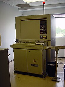
A Philips PW1606 X-ray fluorescence spectrometer with automated sample feed in a cement plant quality control laboratory
 
X-ray fluorescence (XRF) is the emission of characteristic "secondary" (or fluorescent) X-rays from a material that has been excited by being bombarded with high-energy X-rays or gamma rays. The phenomenon is widely used for elemental analysis and chemical analysis, particularly in the investigation of metals, glass, ceramics and building materials, and for research in geochemistry, forensic science, archaeology and art objects such as paintings and murals.

Underlying physics

Figure 1: Physics of X-ray fluorescence in a schematic representation.
 
When materials are exposed to short-wavelength X-rays or to gamma rays, ionization of their component atoms may take place. Ionization consists of the ejection of one or more electrons from the atom, and may occur if the atom is exposed to radiation with an energy greater than its ionization energy. X-rays and gamma rays can be energetic enough to expel tightly held electrons from the inner orbitals of the atom. The removal of an electron in this way makes the electronic structure of the atom unstable, and electrons in higher orbitals "fall" into the lower orbital to fill the hole left behind. In falling, energy is released in the form of a photon, the energy of which is equal to the energy difference of the two orbitals involved. Thus, the material emits radiation, which has energy characteristic of the atoms present. The term fluorescence is applied to phenomena in which the absorption of radiation of a specific energy results in the re-emission of radiation of a different energy (generally lower). 

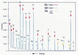
Figure 2: Typical wavelength dispersive XRF spectrum
 
Figure 3: Spectrum of a rhodium target tube operated at 60 kV, showing continuous spectrum and K lines

Characteristic radiation

Each element has electronic orbitals of characteristic energy. Following removal of an inner electron by an energetic photon provided by a primary radiation source, an electron from an outer shell drops into its place. There are a limited number of ways in which this can happen, as shown in Figure 1. The main transitions are given names: an L→K transition is traditionally called Kα, an M→K transition is called Kβ, an M→L transition is called Lα, and so on. Each of these transitions yields a fluorescent photon with a characteristic energy equal to the difference in energy of the initial and final orbital. The wavelength of this fluorescent radiation can be calculated from Planck's Law:
The fluorescent radiation can be analysed either by sorting the energies of the photons (energy-dispersive analysis) or by separating the wavelengths of the radiation (wavelength-dispersive analysis). Once sorted, the intensity of each characteristic radiation is directly related to the amount of each element in the material. This is the basis of a powerful technique in analytical chemistry. Figure 2 shows the typical form of the sharp fluorescent spectral lines obtained in the wavelength-dispersive method.

Primary radiation

In order to excite the atoms, a source of radiation is required, with sufficient energy to expel tightly held inner electrons. Conventional X-ray generators are most commonly used, because their output can readily be "tuned" for the application, and because higher power can be deployed relative to other techniques. However, gamma ray sources can be used without the need for an elaborate power supply, allowing an easier use in small portable instruments. When the energy source is a synchrotron or the X-rays are focused by an optic like a polycapillary, the X-ray beam can be very small and very intense. As a result, atomic information on the sub-micrometre scale can be obtained. X-ray generators in the range 20–60 kV are used, which allow excitation of a broad range of atoms. The continuous spectrum consists of "bremsstrahlung" radiation: radiation produced when high-energy electrons passing through the tube are progressively decelerated by the material of the tube anode (the "target"). A typical tube output spectrum is shown in Figure 3.

Dispersion

In energy dispersive analysis, the fluorescent X-rays emitted by the material sample are directed into a solid-state detector which produces a "continuous" distribution of pulses, the voltages of which are proportional to the incoming photon energies. This signal is processed by a multichannel analyser (MCA) which produces an accumulating digital spectrum that can be processed to obtain analytical data. 

In wavelength dispersive analysis, the fluorescent X-rays emitted by the material sample are directed into a diffraction grating monochromator. The diffraction grating used is usually a single crystal. By varying the angle of incidence and take-off on the crystal, a single X-ray wavelength can be selected. The wavelength obtained is given by Bragg's law:
where d is the spacing of atomic layers parallel to the crystal surface.

Detection

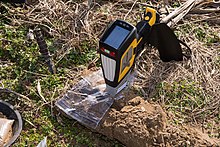
A portable XRF analyzer using a Silicon drift detector
 
In energy dispersive analysis, dispersion and detection are a single operation, as already mentioned above. Proportional counters or various types of solid-state detectors (PIN diode, Si(Li), Ge(Li), Silicon Drift Detector SDD) are used. They all share the same detection principle: An incoming X-ray photon ionises a large number of detector atoms with the amount of charge produced being proportional to the energy of the incoming photon. The charge is then collected and the process repeats itself for the next photon. Detector speed is obviously critical, as all charge carriers measured have to come from the same photon to measure the photon energy correctly (peak length discrimination is used to eliminate events that seem to have been produced by two X-ray photons arriving almost simultaneously). The spectrum is then built up by dividing the energy spectrum into discrete bins and counting the number of pulses registered within each energy bin. EDXRF detector types vary in resolution, speed and the means of cooling (a low number of free charge carriers is critical in the solid state detectors): proportional counters with resolutions of several hundred eV cover the low end of the performance spectrum, followed by PIN diode detectors, while the Si(Li), Ge(Li) and Silicon Drift Detectors (SDD) occupy the high end of the performance scale.

In wavelength dispersive analysis, the single-wavelength radiation produced by the monochromator is passed into a photomultiplier, a detector similar to a Geiger counter, which counts individual photons as they pass through. The counter is a chamber containing a gas that is ionised by X-ray photons. A central electrode is charged at (typically) +1700 V with respect to the conducting chamber walls, and each photon triggers a pulse-like cascade of current across this field. The signal is amplified and transformed into an accumulating digital count. These counts are then processed to obtain analytical data.

X-ray intensity

The fluorescence process is inefficient, and the secondary radiation is much weaker than the primary beam. Furthermore, the secondary radiation from lighter elements is of relatively low energy (long wavelength) and has low penetrating power, and is severely attenuated if the beam passes through air for any distance. Because of this, for high-performance analysis, the path from tube to sample to detector is maintained under vacuum (around 10 Pa residual pressure). This means in practice that most of the working parts of the instrument have to be located in a large vacuum chamber. The problems of maintaining moving parts in vacuum, and of rapidly introducing and withdrawing the sample without losing vacuum, pose major challenges for the design of the instrument. For less demanding applications, or when the sample is damaged by a vacuum (e.g. a volatile sample), a helium-swept X-ray chamber can be substituted, with some loss of low-Z (Z = atomic number) intensities.

Chemical analysis

The use of a primary X-ray beam to excite fluorescent radiation from the sample was first proposed by Glocker and Schreiber in 1928. Today, the method is used as a non-destructive analytical technique, and as a process control tool in many extractive and processing industries. In principle, the lightest element that can be analysed is beryllium (Z = 4), but due to instrumental limitations and low X-ray yields for the light elements, it is often difficult to quantify elements lighter than sodium (Z = 11), unless background corrections and very comprehensive inter-element corrections are made.

Figure 4: Schematic arrangement of EDX spectrometer

Energy dispersive spectrometry

In energy dispersive spectrometers (EDX or EDS), the detector allows the determination of the energy of the photon when it is detected. Detectors historically have been based on silicon semiconductors, in the form of lithium-drifted silicon crystals, or high-purity silicon wafers. 

Figure 5: Schematic form of a Si(Li) detector

Si(Li) detectors

These consist essentially of a 3–5 mm thick silicon junction type p-i-n diode (same as PIN diode) with a bias of −1000 V across it. The lithium-drifted centre part forms the non-conducting i-layer, where Li compensates the residual acceptors which would otherwise make the layer p-type. When an X-ray photon passes through, it causes a swarm of electron-hole pairs to form, and this causes a voltage pulse. To obtain sufficiently low conductivity, the detector must be maintained at low temperature, and liquid-nitrogen cooling must be used for the best resolution. With some loss of resolution, the much more convenient Peltier cooling can be employed.

Wafer detectors

More recently, high-purity silicon wafers with low conductivity have become routinely available. Cooled by the Peltier effect, this provides a cheap and convenient detector, although the liquid nitrogen cooled Si(Li) detector still has the best resolution (i.e. ability to distinguish different photon energies).

Amplifiers

The pulses generated by the detector are processed by pulse-shaping amplifiers. It takes time for the amplifier to shape the pulse for optimum resolution, and there is therefore a trade-off between resolution and count-rate: long processing time for good resolution results in "pulse pile-up" in which the pulses from successive photons overlap. Multi-photon events are, however, typically more drawn out in time (photons did not arrive exactly at the same time) than single photon events and pulse-length discrimination can thus be used to filter most of these out. Even so, a small number of pile-up peaks will remain and pile-up correction should be built into the software in applications that require trace analysis. To make the most efficient use of the detector, the tube current should be reduced to keep multi-photon events (before discrimination) at a reasonable level, e.g. 5–20%.

Processing

Considerable computer power is dedicated to correcting for pulse-pile up and for extraction of data from poorly resolved spectra. These elaborate correction processes tend to be based on empirical relationships that may change with time, so that continuous vigilance is required in order to obtain chemical data of adequate precision.

Usage

EDX spectrometers are different from WDX spectrometers in that they are smaller, simpler in design and have fewer engineered parts, however the accuracy and resolution of EDX spectrometers are lower than for WDX. EDX spectrometers can also use miniature X-ray tubes or gamma sources, which makes them cheaper and allows miniaturization and portability. This type of instrument is commonly used for portable quality control screening applications, such as testing toys for lead (Pb) content, sorting scrap metals, and measuring the lead content of residential paint. On the other hand, the low resolution and problems with low count rate and long dead-time makes them inferior for high-precision analysis. They are, however, very effective for high-speed, multi-elemental analysis. Field Portable XRF analysers currently on the market weigh less than 2 kg, and have limits of detection on the order of 2 parts per million of lead (Pb) in pure sand. Using a Scanning Electron Microscope and using EDX, studies have been broadened to organic based samples such as biological samples and polymers. 

Figure 6: Schematic arrangement of wavelength dispersive spectrometer
 
Chemist operates a goniometer used for X-ray fluorescence analysis of individual grains of mineral specimens, U.S. Geological Survey, 1958.

Wavelength dispersive spectrometry

In wavelength dispersive spectrometers (WDX or WDS), the photons are separated by diffraction on a single crystal before being detected. Although wavelength dispersive spectrometers are occasionally used to scan a wide range of wavelengths, producing a spectrum plot as in EDS, they are usually set up to make measurements only at the wavelength of the emission lines of the elements of interest. This is achieved in two different ways:
  • "Simultaneous" spectrometers have a number of "channels" dedicated to analysis of a single element, each consisting of a fixed-geometry crystal monochromator, a detector, and processing electronics. This allows a number of elements to be measured simultaneously, and in the case of high-powered instruments, complete high-precision analyses can be obtained in under 30 s. Another advantage of this arrangement is that the fixed-geometry monochromators have no continuously moving parts, and so are very reliable. Reliability is important in production environments where instruments are expected to work without interruption for months at a time. Disadvantages of simultaneous spectrometers include relatively high cost for complex analyses, since each channel used is expensive. The number of elements that can be measured is limited to 15–20, because of space limitations on the number of monochromators that can be crowded around the fluorescing sample. The need to accommodate multiple monochromators means that a rather open arrangement around the sample is required, leading to relatively long tube-sample-crystal distances, which leads to lower detected intensities and more scattering. The instrument is inflexible, because if a new element is to be measured, a new measurement channel has to be bought and installed.
  • "Sequential" spectrometers have a single variable-geometry monochromator (but usually with an arrangement for selecting from a choice of crystals), a single detector assembly (but usually with more than one detector arranged in tandem), and a single electronic pack. The instrument is programmed to move through a sequence of wavelengths, in each case selecting the appropriate X-ray tube power, the appropriate crystal, and the appropriate detector arrangement. The length of the measurement program is essentially unlimited, so this arrangement is very flexible. Because there is only one monochromator, the tube-sample-crystal distances can be kept very short, resulting in minimal loss of detected intensity. The obvious disadvantage is relatively long analysis time, particularly when many elements are being analysed, not only because the elements are measured in sequence, but also because a certain amount of time is taken in readjusting the monochromator geometry between measurements. Furthermore, the frenzied activity of the monochromator during an analysis program is a challenge for mechanical reliability. However, modern sequential instruments can achieve reliability almost as good as that of simultaneous instruments, even in continuous-usage applications.

Sample preparation

In order to keep the geometry of the tube-sample-detector assembly constant, the sample is normally prepared as a flat disc, typically of diameter 20–50 mm. This is located at a standardized, small distance from the tube window. Because the X-ray intensity follows an inverse-square law, the tolerances for this placement and for the flatness of the surface must be very tight in order to maintain a repeatable X-ray flux. Ways of obtaining sample discs vary: metals may be machined to shape, minerals may be finely ground and pressed into a tablet, and glasses may be cast to the required shape. A further reason for obtaining a flat and representative sample surface is that the secondary X-rays from lighter elements often only emit from the top few micrometres of the sample. In order to further reduce the effect of surface irregularities, the sample is usually spun at 5–20 rpm. It is necessary to ensure that the sample is sufficiently thick to absorb the entire primary beam. For higher-Z materials, a few millimetres thickness is adequate, but for a light-element matrix such as coal, a thickness of 30–40 mm is needed. 

Figure 7: Bragg diffraction condition

Monochromators

The common feature of monochromators is the maintenance of a symmetrical geometry between the sample, the crystal and the detector. In this geometry the Bragg diffraction condition is obtained.

The X-ray emission lines are very narrow (see figure 2), so the angles must be defined with considerable precision. This is achieved in two ways:
  • Flat crystal with Soller collimators
The Soller collimator is a stack of parallel metal plates, spaced a few tenths of a millimetre apart. To improve angle resolution, one must lengthen the collimator, and/or reduce the plate spacing. This arrangement has the advantage of simplicity and relatively low cost, but the collimators reduce intensity and increase scattering, and reduce the area of sample and crystal that can be "seen". The simplicity of the geometry is especially useful for variable-geometry monochromators. 

Figure 8: Flat crystal with Soller collimators
 
Figure 9: Curved crystal with slits
  • Curved crystal with slits
The Rowland circle geometry ensures that the slits are both in focus, but in order for the Bragg condition to be met at all points, the crystal must first be bent to a radius of 2R (where R is the radius of the Rowland circle), then ground to a radius of R. This arrangement allows higher intensities (typically 8-fold) with higher resolution (typically 4-fold) and lower background. However, the mechanics of keeping Rowland circle geometry in a variable-angle monochromator is extremely difficult. In the case of fixed-angle monochromators (for use in simultaneous spectrometers), crystals bent to a logarithmic spiral shape give the best focusing performance. The manufacture of curved crystals to acceptable tolerances increases their price considerably.

Crystals

The desirable characteristics of a diffraction crystal are:
  • High diffraction intensity
  • High dispersion
  • Narrow diffracted peak width
  • High peak-to-background
  • Absence of interfering elements
  • Low thermal coefficient of expansion
  • Stability in air and on exposure to X-rays
  • Ready availability
  • Low cost
Crystals with simple structure tend to give the best diffraction performance. Crystals containing heavy atoms can diffract well, but also fluoresce themselves, causing interference. Crystals that are water-soluble, volatile or organic tend to give poor stability. 

Commonly used crystal materials include LiF (lithium fluoride), ADP (ammonium dihydrogen phosphate), Ge (germanium), graphite, InSb (indium antimonide), PE (tetrakis-(hydroxymethyl)-methane: penta-erythritol), KAP (potassium hydrogen phthalate), RbAP (rubidium hydrogen phthalate) and TlAP (thallium(I) hydrogen phthalate). In addition, there is an increasing use of "layered synthetic microstructures", which are "sandwich" structured materials comprising successive thick layers of low atomic number matrix, and monatomic layers of a heavy element. These can in principle be custom-manufactured to diffract any desired long wavelength, and are used extensively for elements in the range Li to Mg.

Detectors

Detectors used for wavelength dispersive spectrometry need to have high pulse processing speeds in order to cope with the very high photon count rates that can be obtained. In addition, they need sufficient energy resolution to allow filtering-out of background noise and spurious photons from the primary beam or from crystal fluorescence. There are four common types of detector:
  • Gas flow proportional counters
  • Sealed gas detectors
  • Scintillation counters
  • Semiconductor detectors
Figure 10: Arrangement of gas flow proportional counter
 
Gas flow proportional counters are used mainly for detection of longer wavelengths. Gas flows through it continuously. Where there are multiple detectors, the gas is passed through them in series, then led to waste. The gas is usually 90% argon, 10% methane ("P10"), although the argon may be replaced with neon or helium where very long wavelengths (over 5 nm) are to be detected. The argon is ionised by incoming X-ray photons, and the electric field multiplies this charge into a measurable pulse. The methane suppresses the formation of fluorescent photons caused by recombination of the argon ions with stray electrons. The anode wire is typically tungsten or nichrome of 20–60 μm diameter. Since the pulse strength obtained is essentially proportional to the ratio of the detector chamber diameter to the wire diameter, a fine wire is needed, but it must also be strong enough to be maintained under tension so that it remains precisely straight and concentric with the detector. The window needs to be conductive, thin enough to transmit the X-rays effectively, but thick and strong enough to minimize diffusion of the detector gas into the high vacuum of the monochromator chamber. Materials often used are beryllium metal, aluminised PET film and aluminised polypropylene. Ultra-thin windows (down to 1 μm) for use with low-penetration long wavelengths are very expensive. The pulses are sorted electronically by "pulse height selection" in order to isolate those pulses deriving from the secondary X-ray photons being counted. 

Sealed gas detectors are similar to the gas flow proportional counter, except that the gas does not flow through it. The gas is usually krypton or xenon at a few atmospheres pressure. They are applied usually to wavelengths in the 0.15–0.6 nm range. They are applicable in principle to longer wavelengths, but are limited by the problem of manufacturing a thin window capable of withstanding the high pressure difference. 

Scintillation counters consist of a scintillating crystal (typically of sodium iodide doped with thallium) attached to a photomultiplier. The crystal produces a group of scintillations for each photon absorbed, the number being proportional to the photon energy. This translates into a pulse from the photomultiplier of voltage proportional to the photon energy. The crystal must be protected with a relatively thick aluminium/beryllium foil window, which limits the use of the detector to wavelengths below 0.25 nm. Scintillation counters are often connected in series with a gas flow proportional counter: the latter is provided with an outlet window opposite the inlet, to which the scintillation counter is attached. This arrangement is particularly used in sequential spectrometers. 

Semiconductor detectors can be used in theory, and their applications are increasing as their technology improves, but historically their use for WDX has been restricted by their slow response.

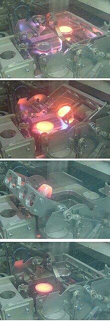
A glass "bead" specimen for XRF analysis being cast at around 1100 °C in a Herzog automated fusion machine in a cement plant quality control laboratory. 1 (top): fusing, 2: preheating the mould, 3: pouring the melt, 4: cooling the "bead"

Extracting analytical results

At first sight, the translation of X-ray photon count-rates into elemental concentrations would appear to be straightforward: WDX separates the X-ray lines efficiently, and the rate of generation of secondary photons is proportional to the element concentration. However, the number of photons leaving the sample is also affected by the physical properties of the sample: so-called "matrix effects". These fall broadly into three categories:
  • X-ray absorption
  • X-ray enhancement
  • Sample macroscopic effects
All elements absorb X-rays to some extent. Each element has a characteristic absorption spectrum which consists of a "saw-tooth" succession of fringes, each step-change of which has wavelength close to an emission line of the element. Absorption attenuates the secondary X-rays leaving the sample. For example, the mass absorption coefficient of silicon at the wavelength of the aluminium Kα line is 50 m²/kg, whereas that of iron is 377 m²/kg. This means that a given concentration of aluminium in a matrix of iron gives only one seventh of the count rate compared with the same concentration of aluminium in a silicon matrix. Fortunately, mass absorption coefficients are well known and can be calculated. However, to calculate the absorption for a multi-element sample, the composition must be known. For analysis of an unknown sample, an iterative procedure is therefore used. It will be noted that, to derive the mass absorption accurately, data for the concentration of elements not measured by XRF may be needed, and various strategies are employed to estimate these. As an example, in cement analysis, the concentration of oxygen (which is not measured) is calculated by assuming that all other elements are present as standard oxides.

Enhancement occurs where the secondary X-rays emitted by a heavier element are sufficiently energetic to stimulate additional secondary emission from a lighter element. This phenomenon can also be modelled, and corrections can be made provided that the full matrix composition can be deduced.

Sample macroscopic effects consist of effects of inhomogeneities of the sample, and unrepresentative conditions at its surface. Samples are ideally homogeneous and isotropic, but they often deviate from this ideal. Mixtures of multiple crystalline components in mineral powders can result in absorption effects that deviate from those calculable from theory. When a powder is pressed into a tablet, the finer minerals concentrate at the surface. Spherical grains tend to migrate to the surface more than do angular grains. In machined metals, the softer components of an alloy tend to smear across the surface. Considerable care and ingenuity are required to minimize these effects. Because they are artifacts of the method of sample preparation, these effects can not be compensated by theoretical corrections, and must be "calibrated in". This means that the calibration materials and the unknowns must be compositionally and mechanically similar, and a given calibration is applicable only to a limited range of materials. Glasses most closely approach the ideal of homogeneity and isotropy, and for accurate work, minerals are usually prepared by dissolving them in a borate glass, and casting them into a flat disc or "bead". Prepared in this form, a virtually universal calibration is applicable. 

Further corrections that are often employed include background correction and line overlap correction. The background signal in an XRF spectrum derives primarily from scattering of primary beam photons by the sample surface. Scattering varies with the sample mass absorption, being greatest when mean atomic number is low. When measuring trace amounts of an element, or when measuring on a variable light matrix, background correction becomes necessary. This is really only feasible on a sequential spectrometer. Line overlap is a common problem, bearing in mind that the spectrum of a complex mineral can contain several hundred measurable lines. Sometimes it can be overcome by measuring a less-intense, but overlap-free line, but in certain instances a correction is inevitable. For instance, the Kα is the only usable line for measuring sodium, and it overlaps the zinc Lβ (L2-M4) line. Thus zinc, if present, must be analysed in order to properly correct the sodium value.

Other spectroscopic methods using the same principle

It is also possible to create a characteristic secondary X-ray emission using other incident radiation to excite the sample:
When radiated by an X-ray beam, the sample also emits other radiations that can be used for analysis:
The de-excitation also ejects Auger electrons, but Auger electron spectroscopy (AES) normally uses an electron beam as the probe. 

Confocal microscopy X-ray fluorescence imaging is a newer technique that allows control over depth, in addition to horizontal and vertical aiming, for example, when analysing buried layers in a painting.

Instrument qualification

A 2001 review, addresses the application of portable instrumentation from QA/QC perspectives. It provides a guide to the development of a set of SOPs if regulatory compliance guidelines are not available.

Radiation protection

From Wikipedia, the free encyclopedia
 Radiation protection, also known as radiological protection, is defined by the International Atomic Energy Agency (IAEA) as "The protection of people from harmful effects of exposure to ionizing radiation, and the means for achieving this". The IAEA also states "The accepted understanding of the term radiation protection is restricted to protection of people. Suggestions to extend the definition to include the protection of non-human species or the protection of the environment are controversial". Exposure can be from a radiation source external to the human body or due to the bodily intake of a radioactive material.

Ionizing radiation is widely used in industry and medicine, and can present a significant health hazard by causing microscopic damage to living tissue. This can result in skin burns and radiation sickness at high exposures, known as "tissue" or "deterministic" effects (conventionally indicated by the gray), and statistically elevated risks of cancer at low exposures, known as "stochastic effects" (conventionally measured by the sievert).

Fundamental to radiation protection is the reduction of expected dose and the measurement of dose uptake. For radiation protection and dosimetry assessment the International Committee on Radiation Protection (ICRP) and International Commission on Radiation Units and Measurements (ICRU) publish recommendations and data which is used to calculate the biological effects on the human body of certain levels of radiation, and thereby advise acceptable dose uptake limits. Supporting these are preventive dose reduction techniques such as radiation shielding, exposure planning and avoidance of ingestion of radioactive substances. Radiation protection instruments are used to indicate radiation hazards, and personal dosimeters and bioassay techniques are used to measure personal dose uptake.

Principles

International policy relationships in radiological protection
 
External dose quantities used in radiation protection and dosimetry - based on ICRU report 57
 
Graphic showing relationships between radioactivity and detected ionizing radiation
 
The ICRP recommends, develops and maintains the International System of Radiological Protection, based on evaluation of the large body of scientific studies available to equate risk to received dose levels. The system's health objectives are "to manage and control exposures to ionising radiation so that deterministic effects are prevented, and the risks of stochastic effects are reduced to the extent reasonably achievable".

The ICRP's recommendations flow down to national and regional regulators, which have the opportunity to incorporate them into their own law; this process is shown in the accompanying block diagram. In most countries a national regulatory authority works towards ensuring a secure radiation environment in society by setting dose limitation requirements that are generally based on the recommendations of the ICRP.

Exposure situations

The ICRP recognises planned, emergency, and existing exposure situations, as described below:
  • Planned exposure – defined as "...where radiological protection can be planned in advance, before exposures occur, and where the magnitude and extent of the exposures can be reasonably predicted." These are such as in occupational exposure situations, where it is necessary for personnel to work in a known radiation environment.
  • Emergency exposure – defined as "...unexpected situations that may require urgent protective actions". This would be such as an emergency nuclear event.
  • Existing exposure – defined as "...being those that already exist when a decision on control has to be taken". These can be such as from naturally occurring radioactive materials which exist in the environment.

Regulation of dose uptake

The ICRP uses the following overall principles for all controllable exposure situations.
  • Justification: No unnecessary use of radiation is permitted, which means that the advantages must outweigh the disadvantages.
  • Limitation: Each individual must be protected against risks that are too great, through the application of individual radiation dose limits.
  • Optimization: This process is intended for application to those situations that have been deemed to be justified. It means "the likelihood of incurring exposures, the number of people exposed, and the magnitude of their individual doses" should all be kept as Low As Reasonably Achievable (known as ALARA or ALARP). It takes into account economic and societal factors.

Factors in external dose uptake

There are three factors that control the amount, or dose, of radiation received from a source. Radiation exposure can be managed by a combination of these factors:
  1. Time: Reducing the time of an exposure reduces the effective dose proportionally. An example of reducing radiation doses by reducing the time of exposures might be improving operator training to reduce the time they take to handle a radioactive source.
  2. Distance: Increasing distance reduces dose due to the inverse square law. Distance can be as simple as handling a source with forceps rather than fingers.
  3. Shielding: Sources of radiation can be shielded with solid or liquid material, which absorbs the energy of the radiation. The term 'biological shield' is used for absorbing material placed around a nuclear reactor, or other source of radiation, to reduce the radiation to a level safe for humans.

Internal dose uptake

Large scale glovebox in the nuclear industry used to contain airborne radioactive particles.
 
Internal dose, due to the inhalation or ingestion of radioactive substances, can result in stochastic or deterministic effects, depending on the amount of radioactive material ingested and other biokinetic factors.

The risk from a low level internal source is represented by the dose quantity committed dose, which has the same risk as the same amount of external effective dose.

The intake of radioactive material can occur through four pathways:
  • Inhalation of airborne contaminants such as radon gas and radioactive particles
  • Ingestion of radioactive contamination in food or liquids
  • Absorption of vapours such as tritium oxide through the skin
  • Injection of medical radioisotopes such as technetium-99m
The occupational hazards from airborne radioactive particles in nuclear and radio-chemical applications are greatly reduced by the extensive use of gloveboxes to contain such material. To protect against breathing in radioactive particles in ambient air, respirators with particulate filters are worn. 

To monitor the concentration of radioactive particles in ambient air, radioactive particulate monitoring instruments measure the concentration or presence of airborne materials.

For ingested radioactive materials in food and drink, specialist laboratory radiometric assay methods are used to measure the concentration of such materials.

Recommended limits on dose uptake

USA Dept of Energy 2010 dose chart in sieverts for a variety of situations and applications.
 
Various doses of radiation in sieverts, ranging from trivial to lethal.
 
The ICRP recommends a number of limits for dose uptake in table 8 of ICRP report 103. These limits are "situational", for planned, emergency and existing situations. Within these situations, limits are given for certain exposed groups:
  • Planned exposure – limits given for occupational, medical and public exposure. The occupational exposure limit of effective dose is 20 mSv per year, averaged over defined periods of 5 years, with no single year exceeding 50 mSv. The public exposure limit is 1 mSv in a year.
  • Emergency exposure – limits given for occupational and public exposure
  • Existing exposure – reference levels for all persons exposed
Further detail of some of the limits can be found on the ICRPedia page.

The public information dose chart of the USA Department of Energy, shown here on the right, applies to USA regulation, which is based on ICRP recommendations. Note that examples in lines 1 to 4 have a scale of dose rate (radiation per unit time), whilst 5 and 6 have a scale of total accumulated dose.

ALARP & ALARA

ALARP is an acronym for an important principle in exposure to radiation and other occupational health risks and in the UK stands for "As Low As Reasonably Practicable". The aim is to minimize the risk of radioactive exposure or other hazard while keeping in mind that some exposure may be acceptable in order to further the task at hand. The equivalent term ALARA, "As Low As Reasonably Achievable", is more commonly used outside the UK. 

This compromise is well illustrated in radiology. The application of radiation can aid the patient by providing doctors and other health care professionals with a medical diagnosis, but the exposure of the patient should be reasonably low enough to keep the statistical probability of cancers or sarcomas (stochastic effects) below an acceptable level, and to eliminate deterministic effects (e.g. skin reddening or cataracts). An acceptable level of incidence of stochastic effects is considered to be equal for a worker to the risk in other radiation work generally considered to be safe.

This policy is based on the principle that any amount of radiation exposure, no matter how small, can increase the chance of negative biological effects such as cancer. It is also based on the principle that the probability of the occurrence of negative effects of radiation exposure increases with cumulative lifetime dose. These ideas are combined to form the linear no-threshold model which says that there is not a threshold at which there is an increase in the rate of occurrence of stochastic effects with increasing dose. At the same time, radiology and other practices that involve use of ionizing radiation bring benefits, so reducing radiation exposure can reduce the efficacy of a medical practice. The economic cost, for example of adding a barrier against radiation, must also be considered when applying the ALARP principle. Computed Tomography, better known as C.T. Scans or CAT Scans have made an enormous contribution to medicine, however not without some risk. They use ionizing radiation which can cause cancer, especially in children. When caregivers follow proper indications for their use and child safe techniques rather than adult techniques, downstream cancer can be prevented.

Personal radiation dosimeters

The radiation dosimeter is an important personal dose measuring instrument. It is worn by the person being monitored and is used to estimate the external radiation dose deposited in the individual wearing the device. They are used for Gamma, X-ray, beta and other strongly penetrating radiation, but not for weakly penetrating radiation such as alpha particles. Traditionally film badges were used for long term monitoring, and quartz fibre dosimeters for short term monitoring. However, these are mostly superseded by such as thermoluminescent dosimetry (TLD) badges and electronic dosimeters. Electronic dosimeters can give an alarm warning if a preset dose threshold has been reached, enabling safer working in potentially higher radiation levels, where the received dose must be continually monitored. 

Workers exposed to radiation, such as radiographers, nuclear power plant workers, doctors using radiotherapy, those in laboratories using radionuclides, and HAZMAT teams are required to wear dosimeters so a record of occupational exposure can be made. Such devices are generally termed "legal dosimeters" if they have been approved for use in recording personnel dose for regulatory purposes. 

Dosimeters can be worn to obtain a whole body dose and there are also specialist types that can be worn on the fingers or clipped to headgear, to measure the localised body irradiation for specific activities. 

Common types of wearable dosimeters for ionizing radiation include:

Radiation shielding

Diagram showing various forms of ionizing radiation, and the sort of material that is used to stop or reduce that type.
 
The total absorption coefficient of lead (atomic number 82) for gamma rays, plotted versus gamma energy, and the contributions by the three effects. Here, the photoelectric effect dominates at low energy. Above 5 MeV, pair production starts to dominate.
 
A lead castle built to shield a radioactive sample in a lab
 
Almost any material can act as a shield from gamma or x-rays if used in sufficient amounts. Different types of ionizing radiation interact in different ways with shielding material. The effectiveness of shielding is dependent on the Stopping power of radiation particles, which varies with the type and energy of radiation and the shielding material used. Different shielding techniques are therefore used dependent on the application and the type and energy of the radiation. 

Shielding reduces the intensity of radiation depending on the thickness. This is an exponential relationship with gradually diminishing effect as equal slices of shielding material are added. A quantity known as the halving-thicknesses is used to calculate this. For example, a practical shield in a fallout shelter with ten halving-thicknesses of packed dirt, which is roughly 115 cm (3 ft 9 in) reduces gamma rays to 1/1024 of their original intensity (i.e. 1/210). 

The effectiveness of a shielding material in general increases with its atomic number, called Z, except for neutron shielding which is more readily shielded by the likes of neutron absorbers and moderators such as compounds of boron e.g. boric acid, cadmium, carbon and hydrogen respectively.

Graded-Z shielding is a laminate of several materials with different Z values (atomic numbers) designed to protect against ionizing radiation. Compared to single-material shielding, the same mass of graded-Z shielding has been shown to reduce electron penetration over 60%. It is commonly used in satellite-based particle detectors, offering several benefits:
  • Protection from radiation damage
  • Reduction of background noise for detectors
  • Lower mass compared to single-material shielding
Designs vary, but typically involve a gradient from high-Z (usually tantalum) through successively lower-Z elements such as tin, steel, and copper, usually ending with aluminium. Sometimes even lighter materials such as polypropylene or boron carbide are used. 

In a typical graded-Z shield, the high-Z layer effectively scatters protons and electrons. It also absorbs gamma rays, which produces X-ray fluorescence. Each subsequent layer absorbs the X-ray fluorescence of the previous material, eventually reducing the energy to a suitable level. Each decrease in energy produces bremsstrahlung and Auger electrons, which are below the detector's energy threshold. Some designs also include an outer layer of aluminium, which may simply be the skin of the satellite. The effectiveness of a material as a biological shield is related to its cross-section for scattering and absorption, and to a first approximation is proportional to the total mass of material per unit area interposed along the line of sight between the radiation source and the region to be protected. Hence, shielding strength or "thickness" is conventionally measured in units of g/cm2. The radiation that manages to get through falls exponentially with the thickness of the shield. In x-ray facilities, walls surrounding the room with the x-ray generator may contain lead sheets, or the plaster may contain barium sulfate. Operators view the target through a leaded glass screen, or if they must remain in the same room as the target, wear lead aprons.

Particle radiation

Particle radiation consists of a stream of charged or neutral particles, both charged ions and subatomic elementary particles. This includes solar wind, cosmic radiation, and neutron flux in nuclear reactors.

Electromagnetic radiation

Electromagnetic radiation consists of emissions of electromagnetic waves, the properties of which depend on the wavelength.
  • X-ray and gamma radiation are best absorbed by atoms with heavy nuclei; the heavier the nucleus, the better the absorption. In some special applications, depleted uranium or thorium are used, but lead is much more common; several centimeters are often required. Barium sulfate is used in some applications too. However, when cost is important, almost any material can be used, but it must be far thicker. Most nuclear reactors use thick concrete shields to create a bioshield with a thin water cooled layer of lead on the inside to protect the porous concrete from the coolant inside. The concrete is also made with heavy aggregates, such as Baryte or MagnaDense (Magnetite), to aid in the shielding properties of the concrete. Gamma rays are better absorbed by materials with high atomic numbers and high density, although neither effect is important compared to the total mass per area in the path of the gamma ray.
  • Ultraviolet (UV) radiation is ionizing in its shortest wavelengths but it is not penetrating, so it can be shielded by thin opaque layers such as sunscreen, clothing, and protective eyewear. Protection from UV is simpler than for the other forms of radiation above, so it is often considered separately.
In some cases, improper shielding can actually make the situation worse, when the radiation interacts with the shielding material and creates secondary radiation that absorbs in the organisms more readily. For example, although high atomic number materials are very effective in shielding photons, using them to shield beta particles may cause higher radiation exposure due to the production of bremsstrahlung x-rays, and hence low atomic number materials are recommended. Also, using material with a high neutron activation cross section to shield neutrons will result in the shielding material itself becoming radioactive and hence more dangerous than if it were not present.

Personal Protective Equipment (PPE) - Radiation

Personal Protection Equipment (PPE) includes all clothing and accessories which can be worn to prevent severe illness and injury as a result of exposure to radioactive material. Because radiation can affect humans through internal and external contamination, various protection strategies have been developed to protect humans from the harmful effects of radiation exposure from a spectrum of sources. A few of these strategies developed to shield from internal, external, and high energy radiation are outlined below.

Internal Contamination Protective Equipment

Internal contamination protection equipment protects against the inhalation and ingestion of radioactive material. Internal deposition of radioactive material result in direct exposure of radiation to organs and tissues inside the body. The respiratory protective equipment described below are designed to minimize the possibility of such material being inhaled or ingested as emergency workers are exposed to potentially radioactive environments.

Reusable Air Purifying Respirators (APR)
  • Elastic face piece worn over the mouth and nose
  • Contains filters, cartridges, and canisters to provide increased protection and better filtration
  • Battery powered blower forces contamination through air purifying filters
  • Purified air delivered under positive pressure to face piece
Supplied-Air Respirator (SAR)
  • Compressed air delivered from a stationary source to the face piece
Auxiliary Escape Respirator
  • Protects wearer from breathing harmful gases, vapors, fumes, and dust
  • Can be designed as an air-purifying escape respirator (APER) or a self-contained breathing apparatus (SCBA) type respirator
  • SCBA type escape respirators have an attached source of breathing air and a hood that provides a barrier against contaminated outside air
  • Provides very pure, dry compressed air to full facepiece mask via a hose
  • Air is exhaled to environment
  • By law, must be worn whenever entering environments immediately dangerous to life and health (IDLH) or when information is inadequate to rule out IDLH atmosphere

External Contamination Protective Equipment

External contamination protection equipment provides a barrier to shield radioactive material from being deposited externally on the body or clothes. The dermal protective equipment described below acts as a barrier to block radioactive material from physically touching the skin, but does not protect against externally penetrating high energy radiation. 

Chemical- Resistant Inner Suit
  • Porous overall suit - Dermal protection from aerosols, dry particles, and non hazardous liquids.
  • Non-porous overall suit to provide dermal protection from:
    • Dry powders and solids
    • Blood-borne pathogens and bio-hazards
    • Chemical splashes and inorganic acid/base aerosols
    • Mild Liquid Chemical Splashes from toxics and corrosices
    • Toxic industrial chemicals and materials
Level C Equivalent: Bunker Gear
  • Fire fighter protective clothing
  • Flame/water resistant
  • Helmet, gloves, foot gear, and hood
Level B Equivalent - Non-gas-tight Encapsulating Suit
  • Designed for environments which are immediately health risks but contain no substances which can be absorbed by skin
Level A Equivalent - Totally Encapsulating Chemical - and Vapor Protective Suit
  • Designed for environments which are immediate health risks and contain substances which can be absorbed by skin

External penetrating radiation

Many solutions to low energy radiation exposure like X-rays already exist. Lead aprons, for example, can protect patients and clinicians from the potentially harmful radiation effects of day to day medical examinations. It is quite feasible to protect large surface areas of the body from radiation in the lower energy spectrum because very little shielding material is required to provide the necessary protection.
Personal shielding against more energetic radiation such as gamma radiation is very difficult to achieve as the large mass of shielding material required to properly protect the entire body would make functional movement nearly impossible. For this, partial body shielding of radio-sensitive internal organs is the most viable protection strategy.

The immediate danger of intense exposure to high energy gamma radiation is Acute Radiation Syndrome (ARS), a result of irreversible bone marrow damage. The concept of selective shielding is based in the regenerative potential of the hematopoietic stem cells found in bone marrow. The regenerative quality of stem cells make it only necessary to protect enough bone marrow to repopulate the body with unaffected stem cells after the exposure: a similar concept which is applied in hematopoietic stem cell transplantation (HSCT) which is a common treatment for patients suffering from leukemia. This scientific advancement allows for the development of a new class of relatively light weight protective equipment which shields high concentrations of bone marrow to defer the hematopoietic sub-syndrome of Acute Radiation Syndrome to much higher dosages.

One technique is to apply selective shielding to protect the high concentration of bone marrow stored in the hips and other radio-sensitive organs in the abdominal area. This allows first responders a safe way to perform necessary missions in radioactive environments. The Organisation for Economic Co-operation and Development (OECD) and the Nuclear Energy Agency (NEA) have published a brief section outlining the benefits of partial body shielding in the 2015 report: Occupational Radiation Protection in Severe Accident Management.

Radiation protection instruments

Practical radiation measurement using calibrated radiation protection instruments is essential in evaluating the effectiveness of protection measures, and in assessing the radiation dose likely to be received by individuals. The measuring instruments for radiation protection are both "installed" (in a fixed position) and portable (hand-held or transportable).

Installed instruments

Installed instruments are fixed in positions which are known to be important in assessing the general radiation hazard in an area. Examples are installed "area" radiation monitors, Gamma interlock monitors, personnel exit monitors, and airborne particulate monitors.

The area radiation monitor will measure the ambient radiation, usually X-Ray, Gamma or neutrons; these are radiations which can have significant radiation levels over a range in excess of tens of metres from their source, and thereby cover a wide area.

Gamma radiation "interlock monitors" are used in applications to prevent inadvertent exposure of workers to an excess dose by preventing personnel access to an area when a high radiation level is present. These interlock the process access directly.

Airborne contamination monitors measure the concentration of radioactive particles in the ambient air to guard against radioactive particles being ingested, or deposited in the lungs of personnel. These instruments will normally give a local alarm, but are often connected to an integrated safety system so that areas of plant can be evacuated and personnel are prevented from entering an air of high airborne contamination.

Personnel exit monitors (PEM) are used to monitor workers who are exiting a "contamination controlled" or potentially contaminated area. These can be in the form of hand monitors, clothing frisk probes, or whole body monitors. These monitor the surface of the workers body and clothing to check if any radioactive contamination has been deposited. These generally measure alpha or beta or gamma, or combinations of these. 

The UK National Physical Laboratory publishes a good practice guide through its Ionising Radiation Metrology Forum concerning the provision of such equipment and the methodology of calculating the alarm levels to be used.

Portable instruments

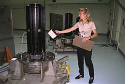
Hand-held ion chamber survey meter in use for surface dose rate on one of three radioisotope thermoelectric generators (RTGs) for the Cassini spacecraft.

Portable instruments are hand-held or transportable. The hand-held instrument is generally used as a survey meter to check an object or person in detail, or assess an area where no installed instrumentation exists. They can also be used for personnel exit monitoring or personnel contamination checks in the field. These generally measure alpha, beta or gamma, or combinations of these.

Transportable instruments are generally instruments that would have been permanently installed, but are temporarily placed in an area to provide continuous monitoring where it is likely there will be a hazard. Such instruments are often installed on trolleys to allow easy deployment, and are associated with temporary operational situations.

In the United Kingdom the HSE has issued a user guidance note on selecting the correct radiation measurement instrument for the application concerned. This covers all radiation instrument technologies, and is a useful comparative guide.

Instrument types

A number of commonly used detection instrument types are listed below, and are used for both fixed and survey monitoring.
The links should be followed for a fuller description of each.

Radiation related quantities

The following table shows the main radiation related quantities and units. 

Ionising radiation related quantities
Quantity Unit Symbol Derivation Year SI equivalence
Activity (A) curie Ci 3.7 × 10¹⁰ s−1 1953 3.7×10¹⁰ Bq
becquerel Bq s−1 1974 SI unit
rutherford Rd 106 s−1 1946 1,000,000 Bq
Exposure (X) röntgen R esu / 0.001293 g of air 1928 2.58 × 10⁻⁴ C/kg
Absorbed dose (D) erg
erg⋅g−1 1950 1.0 × 10⁻⁴ Gy
rad rad 100 erg⋅g−1 1953 0.010 Gy
gray Gy J⋅kg−1 1974 SI unit
Dose equivalent (H) röntgen equivalent man rem 100 erg⋅g−1 1971 0.010 Sv
sievert Sv J⋅kg−1 × WR 1977 SI unit

Spacecraft radiation challenges

Spacecraft, both manned and unmanned, must cope with the high radiation environment of outerspace. Radiation emitted by the Sun and other galactic sources, and trapped in radiation "belts" is more dangerous and hundreds of times more intense than radiation sources such as medical X-rays or normal cosmic radiation usually experienced on Earth. When the intensely ionizing particles found in space strike human tissue, it can result in cell damage and may eventually lead to cancer.

The usual method for radiation protection is material shielding by spacecraft and equipment structures (usually aluminium), possibly augmented by polyethylene in human spaceflight where the main concern is high energy protons and cosmic ray ions. On unmanned spacecraft in high electron dose environments such as Jupiter missions, or medium Earth orbit (MEO), additional shielding with materials of a high atomic number can be effective. On long duration manned missions, advantage can be taken of the good shielding characteristics of liquid hydrogen fuel and water. 

The NASA Space Radiation Laboratory makes use of a particle accelerator that produces beams of protons or heavy ions. These ions are typical of those accelerated in cosmic sources and by the Sun. The beams of ions move through a 100-meter (328-foot) transport tunnel to the 37-square-meter (400-square-foot) shielded target hall. There, they hit the target, which may be a biological sample or shielding material. In a 2002 NASA study, it was determined that materials that have high hydrogen contents, such as polyethylene, can reduce primary and secondary radiation to a greater extent than metals, such as aluminum. The problem with this "passive shielding" method is that radiation interactions in the material generate secondary radiation.

Active Shielding, that is, using magnets, high voltages, or artificial magnetospheres to slow down or deflect radiation, has been considered to potentially combat radiation in a feasible way. So far, the cost of equipment, power and weight of active shielding equipment outweigh their benefits. For example, active radiation equipment would need a habitable volume size to house it, and magnetic and electrostatic configurations often are not homogenous in intensity, allowing high-energy particles to penetrate the magnetic and electric fields from low-intensity parts, like cusps in dipolar magnetic field of Earth. As of 2012, NASA is undergoing research in superconducting magnetic architecture for potential active shielding applications.

Early radiation dangers

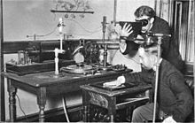
Using early Crookes tube X-Ray apparatus in 1896. One man is viewing his hand with a fluoroscope to optimise tube emissions, the other has his head close to the tube. No precautions are being taken.
 
Monument to the X-ray and Radium Martyrs of All Nations erected 1936 at St. Georg hospital in Hamburg, commemorating 359 early radiology workers.
 
The dangers of radioactivity and radiation were not immediately recognized. The discovery of x‑rays in 1895 led to widespread experimentation by scientists, physicians, and inventors. Many people began recounting stories of burns, hair loss and worse in technical journals as early as 1896. In February of that year, Professor Daniel and Dr. Dudley of Vanderbilt University performed an experiment involving x-raying Dudley's head that resulted in his hair loss. A report by Dr. H.D. Hawks, a graduate of Columbia College, of his suffering severe hand and chest burns in an x-ray demonstration, was the first of many other reports in Electrical Review.

Many experimenters including Elihu Thomson at Thomas Edison's lab, William J. Morton, and Nikola Tesla also reported burns. Elihu Thomson deliberately exposed a finger to an x-ray tube over a period of time and suffered pain, swelling, and blistering. Other effects, including ultraviolet rays and ozone were sometimes blamed for the damage. Many physicists claimed that there were no effects from x-ray exposure at all.

As early as 1902 William Herbert Rollins wrote almost despairingly that his warnings about the dangers involved in careless use of x-rays was not being heeded, either by industry or by his colleagues. By this time Rollins had proved that x-rays could kill experimental animals, could cause a pregnant guinea pig to abort, and that they could kill a fetus. He also stressed that "animals vary in susceptibility to the external action of X-light" and warned that these differences be considered when patients were treated by means of x-rays.

Before the biological effects of radiation were known, many physicists and corporations began marketing radioactive substances as patent medicine in the form of glow-in-the-dark pigments. Examples were radium enema treatments, and radium-containing waters to be drunk as tonics. Marie Curie protested against this sort of treatment, warning that the effects of radiation on the human body were not well understood. Curie later died from aplastic anaemia, likely caused by exposure to ionizing radiation. By the 1930s, after a number of cases of bone necrosis and death of radium treatment enthusiasts, radium-containing medicinal products had been largely removed from the market (radioactive quackery).

Introduction to entropy

From Wikipedia, the free encyclopedia https://en.wikipedia.org/wiki/Introduct...