Search This Blog

Monday, December 27, 2021

Non-rocket spacelaunch

From Wikipedia, the free encyclopedia

Non-rocket spacelaunch refers to concepts for launch into space where much of the speed and altitude needed to achieve orbit is provided by a propulsion technique that is not subject to the limits of the rocket equation. A number of alternatives to rockets have been proposed. In some systems, such as a combination launch system, skyhook, rocket sled launch, rockoon, or air launch, a portion of the total delta-v may be provided, either directly or indirectly, by using rocket propulsion.

Present-day launch costs are very high – $2,500 to $25,000 per kilogram from Earth to low Earth orbit (LEO). As a result, launch costs are a large percentage of the cost of all space endeavors. If launch can be made cheaper, the total cost of space missions will be reduced. Due to the exponential nature of the rocket equation, providing even a small amount of the velocity to LEO by other means has the potential of greatly reducing the cost of getting to orbit.

Launch costs in the hundreds of dollars per kilogram would make possible many proposed large-scale space projects such as space colonization, space-based solar power and terraforming Mars.

Comparison of space launch methods

Method Publication year Estimated build cost
(billion US$)
Payload mass (kg) Estimated cost to LEO (US$/kg) Capacity (t/year) Technology readiness level
Expendable rocket 1903
225 – 130,000 4,000 – 20,000 n/a 9
Space elevator 1895


2
Non-rotating skyhook 1990 < 1


2
Hypersonic skyhook 1993 < 1 1,500
30 2
Rotovator 1977


2
Hypersonic Airplane Space Tether Orbital Launch (HASTOL) 2000
15,000

2
Space fountain 1980s


Orbital ring 1980 15 2×10¹¹ < 0.05 4×10¹⁰ 2
Launch loop (small) 1985 10 5,000 300 40,000 2+
Launch loop (large) 1985 30 5,000 3 6,000,000 2+
KITE Launcher 2005


2
StarTram 2001 20 35,000 43 150,000 2
Space gun 1865 0.5 450 1100
6
Ram accelerator 2004


6
Slingatron 1998
100

2 to 4
Orbital airship


0.34

Static structures

In this usage, the term "static" is intended to convey the understanding that the structural portion of the system has no internal moving parts.

Space tower

A space tower is a tower that would reach outer space. To avoid an immediate need for a vehicle launched at orbital velocity to raise its perigee, a tower would have to extend above the edge of space (above the 100 km Kármán line), but a far lower tower height could reduce atmospheric drag losses during ascent. If the tower went all the way to geosynchronous orbit at approximately 35,999 kilometres (22,369 mi), objects released at such height could then drift away with minimal power and would be in a circular orbit. The concept of a structure reaching to geosynchronous orbit was first conceived by Konstantin Tsiolkovsky. The original concept envisioned by Tsiolkovsky was a compression structure. Building a compression structure from the ground up proved an unrealistic task as there was no material in existence with enough compressive strength to support its own weight under such conditions. Other ideas use very tall compressive towers to reduce the demands on launch vehicles. The vehicle is "elevated" up the tower, which may extend above the atmosphere and is launched from the top. Such a tall tower to access near-space altitudes of 20 km (12 mi) has been proposed by various researchers.

Tensile structures

Tensile structures for non-rocket spacelaunch are proposals to use long, very strong cables (known as tethers) to lift a payload into space. Tethers can also be used for changing orbit once in space.

Orbital tethers can be tidally locked (skyhook) or rotating (rotovators). They can be designed (in theory) to pick up the payload when the payload is stationary or when the payload is hypersonic (has a high but not orbital velocity).

Endo-atmospheric tethers can be used to transfer kinetics (energy and momentum) between large conventional aircraft (subsonic or low supersonic) or other motive force and smaller aerodynamic vehicles, propelling them to hypersonic velocities without exotic propulsion systems.

Skyhook

A rotating and non-rotating skyhooks in orbit

A skyhook is a theoretical class of orbiting tether propulsion intended to lift payloads to high altitudes and speeds. Proposals for skyhooks include designs that employ tethers spinning at hypersonic speed for catching high speed payloads or high altitude aircraft and placing them in orbit.

Space elevator

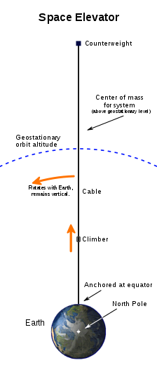
Diagram of a space elevator. At the bottom of the tall diagram is the Earth as viewed from high above the North Pole. About six Earth-radii above the Earth an arc is drawn with the same center as the Earth. The arc depicts the level of geosynchronous orbit. About twice as high as the arc and directly above the Earth's center, a counterweight is depicted by a small square. A line depicting the space elevator's cable connects the counterweight to the equator directly below it. The system's center of mass is described as above the level of geosynchronous orbit. The center of mass is shown roughly to be about a quarter of the way up from the geosynchronous arc to the counterweight. The bottom of the cable is indicated to be anchored at the equator. A climber is depicted by a small rounded square. The climber is shown climbing the cable about one third of the way from the ground to the arc. Another note indicates that the cable rotates along with the Earth's daily rotation, and remains vertical.
A space elevator would consist of a cable anchored to the Earth's surface, reaching into space.

A space elevator is a proposed type of space transportation system. Its main component is a ribbon-like cable (also called a tether) anchored to the surface and extending into space above the level of geosynchronous orbit. As the planet rotates, the centrifugal force at the upper end of the tether counteracts gravity, and keeps the cable taut. Vehicles can then climb the tether and reach orbit without the use of rocket propulsion.

Such a cable could be made out of any material able to support itself under tension by tapering the cable's diameter sufficiently quickly as it approached the Earth's surface. On Earth, with its relatively strong gravity, current materials are not sufficiently strong and light. With conventional materials, the taper ratio would need to be very large, increasing the total launch mass to a fiscally infeasible degree. However, carbon nanotube- or boron nitride nanotube-based materials have been proposed as the tensile element in the tether design. Their measured strengths are high compared to their linear densities. They hold promise as materials to make an Earth-based space elevator possible.

Landis and Cafarelli suggested that a tension structure ("space elevator") extending downward from geosynchronous orbit could be combined with the compression structure ("Tsiolkovski tower") extending upward from the surface, forming the combined structure reaching geosynchronous orbit from the surface, and having structural advantages over either one individually.

The space elevator concept is also applicable to other planets and celestial bodies. For locations in the Solar System with weaker gravity than Earth's (such as the Moon or Mars), the strength-to-density requirements aren't as great for tether materials. Currently available materials (such as Kevlar) could serve as the tether material for elevators there.

Endo-atmospheric tethers

KITE Launcher — transferring momentum to the vehicle.

An endo-atmospheric tether uses the long cable within the atmosphere to provide some or all of the velocity needed to reach orbit. The tether is used to transfer kinetics (energy and momentum) from a massive, slow end (typically a large subsonic or low supersonic aircraft) to a hypersonic end through aerodynamics or centripetal action. The Kinetics Interchange TEther (KITE) Launcher is one proposed endo-atmospheric tether.

Dynamic structures

Space fountain

Hyde design space fountain.

A space fountain is a proposed form of space elevator that does not require the structure to be in geosynchronous orbit, and does not rely on tensile strength for support. In contrast to the original space elevator design (a tethered satellite), a space fountain is a tremendously tall tower extending up from the ground. Since such a tall tower could not support its own weight using traditional materials, massive pellets are projected upward from the bottom of the tower and redirected back down once they reach the top, so that the force of redirection holds the top of the tower aloft.

Orbital ring

Orbital ring.

An orbital ring is a concept for a giant artificially constructed ring hanging at low Earth orbit that would rotate at slightly above orbital speed that would have fixed tethers hanging down to the ground.

In a series of 1982 articles published in the Journal of the British Interplanetary Society, Paul Birch presented the concept of orbital ring systems. He proposed a rotating cable placed in a low Earth orbit, rotating at slightly faster than orbital speed. Not in orbit, but riding on this ring, supported electromagnetically on superconducting magnets, are ring stations that stay in one place above some designated point on Earth. Hanging down from these ring stations are short space elevators made from cables with high tensile-strength-to-mass ratio. Birch claimed that the ring stations, in addition to holding the tether, could accelerate the orbital ring eastwards, causing it to precess around Earth.

In 1982 the Belarusian inventor Anatoly Yunitskiy also proposed an electromagnetic track encircling the Earth, which he called the "String Transportation System." When the velocity of the string exceeds 10 km/sec, centrifugal forces would detach the string from the Earth's surface and lift the ring into space.

Launch loop

Launch loop.

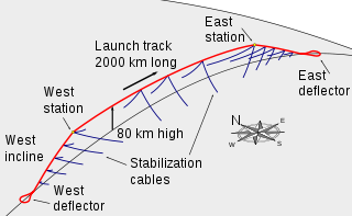
A launch loop or Lofstrom loop is a design for a belt-based maglev orbital launch system that would be around 2000 km long and maintained at an altitude of up to 80 kilometres (50 mi). Vehicles weighing 5 metric tons would be electromagnetically accelerated on top of the cable which forms an acceleration track, from which they would be projected into Earth orbit or even beyond. The structure would constantly need around 200 MW of power to keep it in place.

The system is designed to be suitable for launching humans for space tourism, space exploration and space colonization with a maximum of 3 g acceleration.

Pneumatic freestanding tower

One proposed design is a freestanding tower composed of high strength material (e.g. kevlar) tubular columns inflated with a low density gas mix, and with dynamic stabilization systems including gyroscopes and "pressure balancing". Suggested benefits in contrast to other space elevator designs include avoiding working with the great lengths of structure involved in some other designs, construction from the ground instead of orbit, and functional access to the entire range of altitudes within the design's practical reach. The design presented is "at 5 km altitude and extending to 20 km above sea level", and the authors suggest that "the approach may be further scaled to provide direct access to altitudes above 200 km".

A major difficulty of such a tower is buckling since it is a long slender construction.

Projectile launchers

With any of these projectile launchers, the launcher gives a high velocity at, or near, ground level. In order to achieve orbit, the projectile must be given enough extra velocity to punch through the atmosphere, unless it includes an additional propulsion system (such as a rocket). Also, the projectile needs either an internal or external means to perform orbital insertion. The designs below fall into three categories, electrically driven, chemically driven, and mechanically driven.

Electromagnetic acceleration

Electrical launch systems include mass drivers, railguns, and coilguns. All of these systems use the concept of a stationary launch track which uses some form of linear electrical motor to accelerate a projectile.

Mass driver

A mass driver for lunar launch (artist's conception).
 
Electro-dynamic interactions in a railgun.

In essence, a mass driver is a very long and mainly horizontally aligned launch track or tunnel for accelerating payloads to orbital or suborbital velocities. The concept was proposed by Arthur C. Clarke in 1950, and was developed in more detail by Gerard K. O'Neill, working with the Space Studies Institute, focusing on the use of a mass driver for launching material from the Moon.

A mass driver uses some sort of repulsion to keep a payload separated from the track or walls. Then it uses a linear motor (an alternating-current motor such as in a coil gun, or a homopolar motor as in a railgun) to accelerate the payload to high speeds. After leaving the launch track, the payload would be at its launch velocity.

StarTram

StarTram is a proposal to launch vehicles directly to space by accelerating them with a mass driver. Vehicles would float by maglev repulsion between superconductive magnets on the vehicle and the aluminum tunnel walls while they were accelerated by AC magnetic drive from aluminum coils. The power required would probably be provided by superconductive energy storage units distributed along the tunnel. Vehicles could coast up to low or even geosynchronous orbital height; then a small rocket motor burn would be required to circularize the orbit.

Cargo-only Generation 1 systems would accelerate at 10–20 Gs and exit from a mountain top. While not suitable for passengers, they could put cargo into orbit for $40 per kilogram, 100 times cheaper than rockets.

Passenger-capable Generation 2 systems would accelerate for a much longer distance at 2 Gs. The vehicles would enter the atmosphere at an altitude of 20 km from an evacuated tunnel restrained by Kevlar tethers and supported by magnetic repulsion between superconducting cables in the tunnel and on the ground. For both Gen 1–2 systems, the mouth of the tube would be open during vehicle acceleration, with air kept out by magnetohydrodynamic pumping.

Chemical

Space gun

Project HARP, a prototype of a space gun.

A space gun is a proposed method of launching an object into outer space using a large gun, or cannon. Science fiction writer Jules Verne proposed such a launch method in From the Earth to the Moon, and in 1902 a movie, A Trip to the Moon, was adapted.

However, even with a "gun barrel" through both the Earth's crust and troposphere, the g-forces required to generate escape velocity would still be more than what a human tolerates. Therefore, the space gun would be restricted to freight and ruggedized satellites. Also, the projectile needs either an internal or external means to stabilize on orbit.

Gun launch concepts do not always use combustion. In pneumatic launch systems, a projectile is accelerated in a long tube by air pressure, produced by ground-based turbines or other means. In a light-gas gun, the pressurant is a gas of light molecular weight, to maximize the speed of sound in the gas.

John Hunter of Green Launch proposes use of a 'Hydrogen Gun' to launch uncrewed payloads to orbit for less than the regular launch costs.

Ram accelerator

A ram accelerator also uses chemical energy like the space gun but it is entirely different in that it relies on a jet-engine-like propulsion cycle utilizing ramjet and/or scramjet combustion processes to accelerate the projectile to extremely high speeds.

It is a long tube filled with a mixture of combustible gases with a frangible diaphragm at either end to contain the gases. The projectile, which is shaped like a ram jet core, is fired by another means (e.g., a space gun, discussed above) supersonically through the first diaphragm into the end of the tube. It then burns the gases as fuel, accelerating down the tube under jet propulsion. Other physics come into play at higher velocities.

Blast wave accelerator

A blast wave accelerator is similar to a space gun but it differs in that rings of explosive along the length of the barrel are detonated in sequence to keep the accelerations high. Also, rather than just relying on the pressure behind the projectile, the blast wave accelerator specifically times the explosions to squeeze on a tail cone on the projectile, as one might shoot a pumpkin seed by squeezing the tapered end.

Mechanical

Slingatron

In a slingatron, projectiles are accelerated along a rigid tube or track that typically has circular or spiral turns, or combinations of these geometries in two or three dimensions. A projectile is accelerated in the curved tube by propelling the entire tube in a small-amplitude circular motion of constant or increasing frequency without changing the orientation of the tube, i.e. the entire tube gyrates but does not spin. An everyday example of this motion is stirring a beverage by holding the container and moving it in small horizontal circles, causing the contents to spin, without spinning the container itself.

This gyration continually displaces the tube with a component along the direction of the centripetal force acting on the projectile, so that work is continually done on the projectile as it advances through the machine. The centripetal force experienced by the projectile is the accelerating force, and is proportional to the projectile mass.

Air launch

In air launch, a carrier aircraft carries the space vehicle to high altitude and speed before release. This technique was used on the suborbital X-15 and SpaceshipOne vehicles, and for the Pegasus orbital launch vehicle.

The main disadvantages are that the carrier aircraft tends to be quite large, and separation within the airflow at supersonic speeds has never been demonstrated, thus the boost given is relatively modest.

Spaceplanes

Artist's conception of NASA's X-43A hypersonic aircraft with scramjet attached to the underside.

A spaceplane is an aircraft designed to pass the edge of space. It combines some features of an aircraft with some of a spacecraft. Typically, it takes the form of a spacecraft equipped with aerodynamic surfaces, one or more rocket engines, and sometimes additional airbreathing propulsion as well.

Early spaceplanes were used to explore hypersonic flight (e.g. X-15).

Some air-breathing engine-based designs (cf X-30) such as aircraft based on scramjets or pulse detonation engines could potentially achieve orbital velocity or go some useful way to doing so; however, these designs still must perform a final rocket burn at their apogee to circularize their trajectory to avoid returning to the atmosphere. Other, reusable turbojet-like designs like Skylon which uses precooled jet engines up to Mach 5.5 before employing rockets to enter orbit appears to have a mass budget that permits a larger payload than pure rockets while achieving it in a single stage.

Balloon

Balloons can raise the initial altitude of rockets. However, balloons have relatively low payload (although see the Sky Cat project for an example of a heavy-lift balloon intended for use in the lower atmosphere), and this decreases even more with increasing altitude.

The lifting gas could be helium or hydrogen. Helium is not only expensive in large quantities but is also a nonrenewable resource. This makes balloons an expensive launch assist technique. Hydrogen could be used as it has the advantage of being cheaper and lighter than helium, but the disadvantage of also being highly flammable. Rockets launched from balloons, known as "rockoons", have been demonstrated, but, to date, only for suborbital ("sounding rocket") missions. The size of balloon that would be required to lift an orbital launch vehicle would be extremely large.

One prototype of a balloon launch platform has been made by JP Aerospace as "Project Tandem", although it has not been used as a rocket launch vehicle. JP Aerospace further proposes a hypersonic, lighter than air upper stage. A Spanish company, zero2infinity, is officially developing a launcher system called bloostar based on the rockoon concept, expected to be operational by 2018.

Gerard K. O'Neill proposed that by using very large balloons it may be possible to construct a space port in the stratosphere. Rockets could launch from it or a mass driver could accelerate payloads into the orbit. This has the advantage that most (about 90%) of the atmosphere is below the space port. A SpaceShaft is a proposed version of an atmospherically buoyant structure that would serve as a system to lift cargo to near-space altitudes, with platforms distributed at several elevations that would provide habitation facilities for long term human operations throughout the mid-atmosphere and near-space altitudes. For space launch, it would serve as a non-rocket first stage for rockets launched from the top.

Hybrid launch systems

NASA art for a concept combining three technologies: electromagnetic launch assist from a hypothetical 2-mile (3.2 km) track at Kennedy Space Center, a scramjet aircraft, and a carried rocket for use after air launch reaches orbit.

Separate technologies may be combined. In 2010, NASA suggested that a future scramjet aircraft might be accelerated to 300 m/s (a solution to the problem of ramjet engines not being startable at zero airflow velocity) by electromagnetic or other sled launch assist, in turn air-launching a second-stage rocket delivering a satellite to orbit.

All forms of projectile launchers are at least partially hybrid systems if launching to low Earth orbit, due to the requirement for orbit circularization, at a minimum entailing approximately 1.5 percent of the total delta-v to raise perigee (e.g. a tiny rocket burn), or in some concepts much more from a rocket thruster to ease ground accelerator development.

Some technologies can have exponential scaling if used in isolation, making the effect of combinations be of counter-intuitive magnitude. For instance, 270 m/s is under 4% of the velocity of low Earth orbit, but a NASA study estimated that Maglifter sled launch at that velocity could increase the payload of a conventional ELV rocket by 80% when also having the track go up a 3000‑meter mountain.

Forms of ground launch limited to a given maximum acceleration (such as due to human g-force tolerances if intended to carry passengers) have the corresponding minimum launcher length scale not linearly but with velocity squared. Tethers can have even more non-linear, exponential scaling. The tether-to-payload mass ratio of a space tether would be around 1:1 at a tip velocity 60% of its characteristic velocity but becomes more than 1000:1 at a tip velocity 240% of its characteristic velocity. For instance, for anticipated practicality and a moderate mass ratio with current materials, the HASTOL concept would have the first half (4 km/s) of velocity to orbit be provided by other means than the tether itself.

A proposal to use a hybrid system combining a mass driver for initial lofting followed by additive thrust by a series of ground-based lasers sequenced according to wavelength was proposed by Mashall Savage in the book The Millennial Project as one of the core theses of the book, but the idea has not been pursued to any notable degree. Savage's specific proposals proved to be infeasible on both engineering and political grounds, and while the difficulties could be overcome, the group Savage founded, now called the Living Universe Foundation, has been unable to raise significant funds for research.

Combining multiple technologies would in itself be an increase to complexity and development challenges, but reducing the performance requirements of a given subsystem may allow reduction in its individual complexity or cost. For instance, the number of parts in a liquid-fueled rocket engine may be two orders of magnitude less if pressure-fed rather than pump-fed if its delta-v requirements are limited enough to make the weight penalty of such be a practical option, or a high-velocity ground launcher may be able to use a relatively moderate performance and inexpensive solid fuel or hybrid small motor on its projectile. Assist by non-rocket methods may compensate against the weight penalty of making an orbital rocket reusable. Though suborbital, the first private crewed spaceship, SpaceShipOne had reduced rocket performance requirements due to being a combined system with its air launch.

  • References in this column apply to entire row unless specifically replaced.

  • All monetary values in un-inflated dollars based on reference publication date except as noted.

  • CY2008 estimate from description in 1993 reference system.

  • Requires first stage to ~ 5 km/s.

  • Subject to very rapid increase via bootstrapping.

  • Requires Boeing proposed DF-9 vehicle first stage to ~ 4 km/s.

  • Based on Gen-1 reference design, 2010 version.
  • Space tether

    From Wikipedia, the free encyclopedia
     
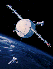
    Artist's conception of satellite with a tether

    Space tethers are long cables which can be used for propulsion, momentum exchange, stabilization and attitude control, or maintaining the relative positions of the components of a large dispersed satellite/spacecraft sensor system. Depending on the mission objectives and altitude, spaceflight using this form of spacecraft propulsion is theorized to be significantly less expensive than spaceflight using rocket engines.

    Main techniques

    Tether satellites might be used for various purposes, including research into tether propulsion, tidal stabilization and orbital plasma dynamics. Five main techniques for employing space tethers are in development:

    Electrodynamic tethers

    Electrodynamic tethers are primarily used for propulsion. These are conducting tethers that carry a current that can generate either thrust or drag from a planetary magnetic field, in much the same way as an electric motor does.

    Momentum exchange tethers

    These can be either rotating tethers, or non-rotating tethers, that capture an arriving spacecraft and then release it at a later time into a different orbit with a different velocity. Momentum exchange tethers can be used for orbital maneuvering, or as part of a planetary-surface-to-orbit / orbit-to-escape-velocity space transportation system.

    Tethered formation flying

    This is typically a non-conductive tether that accurately maintains a set distance between multiple space vehicles flying in formation.

    Electric sail

    A form of solar wind sail with electrically charged tethers that will be pushed by the momentum of solar wind ions.

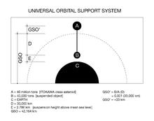
    Universal Orbital Support System

    A concept for suspending an object from a tether orbiting in space.

    Many uses for space tethers have been proposed, including deployment as space elevators, as skyhooks, and for doing propellant-free orbital transfers.

    History

    Konstantin Tsiolkovsky (1857-1935) once proposed a tower so tall that it reached into space, so that it would be held there by the rotation of Earth. However, at the time, there was no realistic way to build it.

    In 1960, another Russian, Yuri Artsutanov, wrote in greater detail about the idea of a tensile cable to be deployed from a geosynchronous satellite, downwards towards the ground, and upwards away, keeping the cable balanced. This is the space elevator idea, a type of synchronous tether that would rotate with the earth. However, given the materials technology of the time, this too was impractical on Earth.

    In the 1970s, Jerome Pearson independently conceived the idea of a space elevator, sometimes referred to as a synchronous tether, and, in particular, analyzed a lunar elevator that can go through the L1 and L2 points, and this was found to be possible with materials then existing.

    In 1977, Hans Moravec and later Robert L. Forward investigated the physics of non-synchronous skyhooks, also known as rotating skyhooks, and performed detailed simulations of tapered rotating tethers that could pick objects off, and place objects onto, the Moon, Mars and other planets, with little loss, or even a net gain of energy.

    In 1979, NASA examined the feasibility of the idea and gave direction to the study of tethered systems, especially tethered satellites.

    In 1990, E. Sarmont proposed a non-rotating Orbiting Skyhook for an Earth-to-orbit / orbit-to-escape-velocity Space Transportation System in a paper titled "An Orbiting Skyhook: Affordable Access to Space". In this concept a suborbital launch vehicle would fly to the bottom end of a Skyhook, while spacecraft bound for higher orbit, or returning from higher orbit, would use the upper end.

    In 2000, NASA and Boeing considered a HASTOL concept, where a rotating tether would take payloads from a hypersonic aircraft (at half of orbital velocity) to orbit.

    Missions

    Graphic of the US Naval Research Laboratory's TiPS tether satellite. Only a small part of the 4 km tether is shown deployed.
     

    A tether satellite is a satellite connected to another by a space tether. A number of satellites have been launched to test tether technologies, with varying degrees of success.

    Types

    There are many different (and overlapping) types of tether.

    Momentum exchange tethers, rotating

    Momentum exchange tethers are one of many applications for space tethers. Momentum exchange tethers come in two types; rotating and non-rotating. A rotating tether will create a controlled force on the end-masses of the system due to centrifugal acceleration. While the tether system rotates, the objects on either end of the tether will experience continuous acceleration; the magnitude of the acceleration depends on the length of the tether and the rotation rate. Momentum exchange occurs when an end body is released during the rotation. The transfer of momentum to the released object will cause the rotating tether to lose energy, and thus lose velocity and altitude. However, using electrodynamic tether thrusting, or ion propulsion the system can then re-boost itself with little or no expenditure of consumable reaction mass.

    Skyhook

    A rotating and a tidally stabilised skyhook in orbit

    A skyhook is a theoretical class of orbiting tether propulsion intended to lift payloads to high altitudes and speeds. Proposals for skyhooks include designs that employ tethers spinning at hypersonic speed for catching high speed payloads or high altitude aircraft and placing them in orbit.

    Electrodynamics

    Medium close-up view, captured with a 70 mm camera, shows Tethered Satellite System deployment.
     

    Electrodynamic tethers are long conducting wires, such as one deployed from a tether satellite, which can operate on electromagnetic principles as generators, by converting their kinetic energy to electrical energy, or as motors, converting electrical energy to kinetic energy. Electric potential is generated across a conductive tether by its motion through the earth's magnetic field. The choice of the metal conductor to be used in an electrodynamic tether is determined by a variety of factors. Primary factors usually include high electrical conductivity and low density. Secondary factors, depending on the application, include cost, strength, and melting point.

    An electrodynamic tether was profiled in the documentary film Orphans of Apollo as technology that was to be used to keep the Russian space station Mir in orbit.

    Formation flying

    This is the use of a (typically) non-conductive tether to connect multiple spacecraft. A proposed 2011 experiment to study the technique is the Tethered Experiment for Mars inter-Planetary Operations (TEMPO³).

    Universal Orbital Support System

    Example of a possible layout using the Universal Orbital Support System.

    A theoretical type of non-rotating tethered satellite system, it is a concept for providing space-based support to things suspended above an astronomical object. The orbital system is a coupled mass system wherein the upper supporting mass (A) is placed in an orbit around a given celestial body such that it can support a suspended mass (B) at a specific height above the surface of the celestial body, but lower than (A).

    Technical difficulties

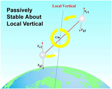
    Gravitational gradient stabilization

    Description of the forces contributing towards maintaining a gravity gradient alignment in a tether system
     

    Instead of rotating end for end, tethers can also be kept straight by the slight difference in the strength of gravity over their length.

    A non-rotating tether system has a stable orientation that is aligned along the local vertical (of the earth or other body). This can be understood by inspection of the figure on the right where two spacecraft at two different altitudes have been connected by a tether. Normally, each spacecraft would have a balance of gravitational (e.g. Fg1) and centrifugal (e.g. Fc1) forces, but when tied together by a tether, these values begin to change with respect to one another. This phenomenon occurs because, without the tether, the higher-altitude mass would travel slower than the lower mass. The system must move at a single speed, so the tether must therefore slow down the lower mass and speed up the upper one. The centrifugal force of the tethered upper body is increased, while that of the lower-altitude body is reduced. This results in the centrifugal force of the upper body and the gravitational force of the lower body being dominant. This difference in forces naturally aligns the system along the local vertical, as seen in the figure.

    Atomic oxygen

    Objects in low Earth orbit are subjected to noticeable erosion from atomic oxygen due to the high orbital speed with which the molecules strike as well as their high reactivity. This could quickly erode a tether.

    Micrometeorites and space junk

    Simple single-strand tethers are susceptible to micrometeoroids and space junk. Several systems have since been proposed and tested to improve debris resistance:

    • The US Naval Research Laboratory has successfully flown a long term 6 km long, 2-3mm diameter tether with an outer layer of Spectra 1000 braid and a core of acrylic yarn. This satellite, the Tether Physics and Survivability Experiment (TiPS), was launched in June 1996 and remained in operation over 10 years, finally breaking in July 2006.
    • Dr. Robert P. Hoyt patented an engineered circular net, such that a cut strand's strains would be redistributed automatically around the severed strand. This is called a Hoytether. Hoytethers have theoretical lifetimes of decades.
    • Researchers with JAXA have also proposed net-based tethers for their future missions.

    Large pieces of junk would still cut most tethers, including the improved versions listed here, but these are currently tracked on radar and have predictable orbits. A tether could be wiggled to dodge known pieces of junk, or thrusters used to change the orbit, avoiding a collision.

    Radiation

    Radiation, including UV radiation tend to degrade tether materials, and reduce lifespan. Tethers that repeatedly traverse the Van Allen belts can have markedly lower life than those that stay in low earth orbit or are kept outside Earth's magnetosphere.

    Construction

    Properties of useful materials

    TSS-1R.
    TSS-1R tether composition [NASA].

    Tether properties and materials are dependent on the application. However, there are some common properties. To achieve maximum performance and low cost, tethers would need to be made of materials with the combination of high strength or electrical conductivity and low density. All space tethers are susceptible to space debris or micrometeroids. Therefore, system designers will need to decide whether or not a protective coating is needed, including relative to UV and atomic oxygen. Research is being conducted to assess the probability of a collision that would damage the tether.

    For applications that exert high tensile forces on the tether, the materials need to be strong and light. Some current tether designs use crystalline plastics such as ultra high molecular weight polyethylene, aramid or carbon fiber. A possible future material would be carbon nanotubes, which have an estimated tensile strength between 140 and 177 GPa (20.3-25.6 million psi), and a proven tensile strength in the range 50-60 GPa for some individual nanotubes. (A number of other materials obtain 10 to 20 GPa in some samples on the nano scale, but translating such strengths to the macro scale has been challenging so far, with, as of 2011, CNT-based ropes being an order of magnitude less strong, not yet stronger than more conventional carbon fiber on that scale).

    For some applications, the tensile force on the tether is projected to be less than 65 newtons (15 lbf). Material selection in this case depends on the purpose of the mission and design constraints. Electrodynamic tethers, such as the one used on TSS-1R, may use thin copper wires for high conductivity (see EDT).

    There are design equations for certain applications that may be used to aid designers in identifying typical quantities that drive material selection.

    Space elevator equations typically use a "characteristic length", Lc, which is also known as its "self-support length" and is the length of untapered cable it can support in a constant 1 g gravity field.

    ,

    where σ is the stress limit (in pressure units) and ρ is the density of the material.

    Hypersonic skyhook equations use the material's "specific velocity" which is equal to the maximum tangential velocity a spinning hoop can attain without breaking:

    For rotating tethers (rotovators) the value used is the material's 'characteristic velocity' which is the maximum tip velocity a rotating untapered cable can attain without breaking,

    The characteristic velocity equals the specific velocity multiplied by the square root of two.

    These values are used in equations similar to the rocket equation and are analogous to specific impulse or exhaust velocity. The higher these values are, the more efficient and lighter the tether can be in relation to the payloads that they can carry. Eventually however, the mass of the tether propulsion system will be limited at the low end by other factors such as momentum storage.

    Practical materials

    Proposed materials include Kevlar, ultra high molecular weight polyethylene, carbon nanotubes and M5 fiber. M5 is a synthetic fiber that is lighter than Kevlar or Spectra. According to Pearson, Levin, Oldson, and Wykes in their article "The Lunar Space Elevator", an M5 ribbon 30 mm wide and 0.023 mm thick, would be able to support 2000 kg on the lunar surface. It would also be able to hold 100 cargo vehicles, each with a mass of 580 kg, evenly spaced along the length of the elevator. Other materials that could be used are T1000G carbon fiber, Spectra 2000, or Zylon.

    Potential tether / elevator materials
    Material Density
    ρ
    (kg/m³)
    Stress limit
    σ
    (GPa)
    Characteristic length
    Lc = σ/ρg
    (km)
    Specific velocity
    Vs = σ/ρ
    (km/s)
    Char. velocity
    Vc = 2σ/ρ
    (km/s)
    Single-wall carbon nanotubes (individual molecules measured) 2266 50 2200 4.7 6.6
    Aramid, polybenzoxazole (PBO) fiber ("Zylon") 1340 5.9 450 2.1 3.0
    Toray carbon fiber (T1000G) 1810 6.4 360 1.9 2.7
    M5 fiber (planned values) 1700 9.5 570 2.4 3.3
    M5 fiber (existing) 1700 5.7 340 1.8 2.6
    Honeywell extended chain polyethylene fiber (Spectra 2000) 970 3.0 316 1.8 2.5
    DuPont Aramid fiber (Kevlar 49) 1440 3.6 255 1.6 2.2
    Silicon carbide 3000 5.9 199 1.4 2.0

    Shape

    Tapering

    For gravity stabilised tethers, to exceed the self-support length the tether material can be tapered so that the cross-sectional area varies with the total load at each point along the length of the cable. In practice this means that the central tether structure needs to be thicker than the tips. Correct tapering ensures that the tensile stress at every point in the cable is exactly the same. For very demanding applications, such as an Earth space elevator, the tapering can reduce the excessive ratios of cable weight to payload weight. In lieu of tapering a modular staged tether system maybe used to achieve the same goal. Multiple tethers would be used between stages. The number of tethers would determine the strength of any given cross-section.

    Thickness

    For rotating tethers not significantly affected by gravity, the thickness also varies, and it can be shown that the area, A, is given as a function of r (the distance from the centre) as follows:

    where R is the radius of tether, v is the velocity with respect to the centre, M is the tip mass, is the material density, and T is the design tensile strength (Young's modulus divided by safety factor).

    Mass ratio

    Graph of tether mass to payload ratio versus the tip speed in multiples of the characteristic speed of the material

    Integrating the area to give the volume and multiplying by the density and dividing by the payload mass gives a payload mass / tether mass ratio of:

    where erf is the normal probability error function.

    Let ,

    then:

    This equation can be compared with the rocket equation, which is proportional to a simple exponent on a velocity, rather than a velocity squared. This difference effectively limits the delta-v that can be obtained from a single tether.

    Redundancy

    In addition the cable shape must be constructed to withstand micrometeorites and space junk. This can be achieved with the use of redundant cables, such as the Hoytether; redundancy can ensure that it is very unlikely that multiple redundant cables would be damaged near the same point on the cable, and hence a very large amount of total damage can occur over different parts of the cable before failure occurs.

    Material strength

    Beanstalks and rotovators are currently limited by the strengths of available materials. Although ultra-high strength plastic fibers (Kevlar and Spectra) permit rotovators to pluck masses from the surface of the Moon and Mars, a rotovator from these materials cannot lift from the surface of the Earth. In theory, high flying, supersonic (or hypersonic) aircraft could deliver a payload to a rotovator that dipped into Earth's upper atmosphere briefly at predictable locations throughout the tropic (and temperate) zone of Earth. As of May 2013, all mechanical tethers (orbital and elevators) are on hold until stronger materials are available.

    Cargo capture

    Cargo capture for rotovators is nontrivial, and failure to capture can cause problems. Several systems have been proposed, such as shooting nets at the cargo, but all add weight, complexity, and another failure mode. At least one lab scale demonstration of a working grapple system has been achieved, however.

    Life expectancy

    Currently, the strongest materials in tension are plastics that require a coating for protection from UV radiation and (depending on the orbit) erosion by atomic oxygen. Disposal of waste heat is difficult in a vacuum, so overheating may cause tether failures or damage.

    Control and modelling

    Pendular motion instability

    Electrodynamic tethers deployed along the local vertical ('hanging tethers') may suffer from dynamical instability. Pendular motion causes the tether vibration amplitude to build up under the action of electromagnetic interaction. As the mission time increases, this behavior can compromise the performance of the system. Over a few weeks, electrodynamic tethers in Earth orbit might build up vibrations in many modes, as their orbit interacts with irregularities in magnetic and gravitational fields.

    One plan to control the vibrations is to actively vary the tether current to counteract the growth of the vibrations. Electrodynamic tethers can be stabilized by reducing their current when it would feed the oscillations, and increasing it when it opposes oscillations. Simulations have demonstrated that this can control tether vibration. This approach requires sensors to measure tether vibrations, which can either be an inertial navigation system on one end of the tether, or satellite navigation systems mounted on the tether, transmitting their positions to a receiver on the end.

    Another proposed method is to use spinning electrodynamic tethers instead of hanging tethers. The gyroscopic effect provides passive stabilisation, avoiding the instability.

    Surges

    As mentioned earlier, conductive tethers have failed from unexpected current surges. Unexpected electrostatic discharges have cut tethers (e.g. see Tethered Satellite System Reflight (TSS‑1R) on STS‑75), damaged electronics, and welded tether handling machinery. It may be that the Earth's magnetic field is not as homogeneous as some engineers have believed.

    Vibrations

    Computer models frequently show tethers can snap due to vibration.

    Mechanical tether-handling equipment is often surprisingly heavy, with complex controls to damp vibrations. The one ton climber proposed by Dr. Brad Edwards for his Space Elevator may detect and suppress most vibrations by changing speed and direction. The climber can also repair or augment a tether by spinning more strands.

    The vibration modes that may be a problem include skipping rope, transverse, longitudinal, and pendulum.

    Tethers are nearly always tapered, and this can greatly amplify the movement at the thinnest tip in whip-like ways.

    Other issues

    A tether is not a spherical object, and has significant extent. This means that as an extended object, it is not directly modelable as a point source, and this means that the center of mass and center of gravity are not usually colocated. Thus the inverse square law does not apply except at large distances, to the overall behaviour of a tether. Hence the orbits are not completely Keplerian, and in some cases they are actually chaotic.

    With bolus designs, rotation of the cable interacting with the non-linear gravity fields found in elliptical orbits can cause exchange of orbital angular momentum and rotation angular momentum. This can make prediction and modelling extremely complex.


    Space tether missions

    From Wikipedia, the free encyclopedia
     
    Graphic of the US Naval Research Laboratory's TiPS tether satellite. Note that only a small part of the 4 km tether is shown deployed.

    A number of space tethers have been deployed in space missions. Tether satellites can be used for various purposes including research into tether propulsion, tidal stabilisation and orbital plasma dynamics.

    The missions have met with varying degrees of success; a few have been highly successful.

    Description

    Tethered satellites are composed of three parts: the base-satellite; tether; and sub-satellite. The base-satellite contains the sub-satellite and tether until deployment. Sometimes the base-satellite is another basic satellite, other times it could be a spacecraft, space station, or the Moon. The tether is what keeps the two satellites connected. The sub-satellite is released from the base assisted by a spring ejection system, centrifugal force or gravity gradient effects.

    Tethers can be deployed for a range of applications, including electrodynamic propulsion, momentum exchange, artificial gravity, deployment of sensors or antennas etc. Tether deployment may be followed by a station-keeping phase (in particular if the target state is a vertical system orientation), and, sometimes, if the deployment system allows, a retraction.

    The station-keeping phase and retraction phase need active control for stability, especially when atmospheric effects are taken into account. When there are no simplifying assumptions, the dynamics become overly difficult because they are then governed by a set of ordinary and partial nonlinear, non-autonomous and coupled differential equations. These conditions create a list of dynamical issues to consider:

    • Three-dimensional rigid body dynamics (librational motion) of the station and subsatellite
    • Swinging in-plane and out-of-plane motions of the tether of finite mass
    • Offset of the tether attachment point from the base-satellite center of mass as well as controlled variations of the offset
    • Transverse vibrations of the tether
    • External forces
    A NASA artist's rendering of a satellite tethered to the space shuttle.

    Tether flights on human space missions

    Gemini 11

    In 1966, Gemini 11 deployed a 30 m (98 ft) tether which was stabilized by a rotation which gave 0.00015 g.

    Shuttle TSS missions

    TSS-1 mission

    Close-up view of the Tethered Satellite System (TSS-1) in orbit above the Space Shuttle Atlantis.

    Tethered Satellite System-1 (TSS-1) was proposed by NASA and the Italian Space Agency (ASI) in the early 1970s by Mario Grossi, of the Smithsonian Astrophysical Observatory, and Giuseppe Colombo, of Padua University. It was a joint NASA-Italian Space Agency project, was flown in 1992, during STS-46 aboard the Space Shuttle Atlantis from 31 July to 8 August.

    The purposes of the TSS-1 mission were to verify the tether concept of gravity gradient stabilization, and to provide a research facility for investigating space physics and plasma electrodynamics. This mission uncovered several aspects about the dynamics of the tethered system, although the satellite did not fully deploy. It stuck at 78 meters; after that snag was resolved its deployment continued to a length of 256 meters (840 ft) before sticking again, where the effort finally ended (the total proposed length was 20,000 meters (66,000 ft)). A protruding bolt due to a late-stage modification of the deployment reel system, jammed the deployment mechanism and prevented deployment to full extension. Despite this issue, the results showed that the basic concept of long gravity-gradient stabilized tethers was sound. It also settled several short deployment dynamics issues, reduced safety concerns, and clearly demonstrated the feasibility of deploying the satellite to long distances.

    The voltage and current reached using the short tether length were too low for most of the experiments to be run. However, low-voltage measurements were made, along with recording the variations of tether-induced forces and currents. New information was gathered on the "return-tether" current. The mission was reflown in 1996 as TSS-1R.

    TSS-1R mission

    Four years later, as a follow-up mission to TSS-1, the TSS-1R satellite was released in latter February 1996 from the Space Shuttle Columbia on the STS-75 mission. The TSS-1R mission objective was to deploy the tether 20.7 km (12.9 mi) above the orbiter and remain there collecting data. The TSS-1R mission was to conduct exploratory experiments in space plasma physics. Projections indicated that the motion of the long conducting tether through the Earth's magnetic field would produce an EMF that would drive a current through the tether system.

    TSS-1R was deployed (over a period of five hours) to 19.7 km (12.2 mi) when the tether broke. The break was attributed to an electrical discharge through a broken place in the insulation.

    Despite the termination of the tether deployment before full extension, the extension achieved was long enough to verify numerous scientific speculations. These findings included the measurements of the motional EMF, the satellite potential, the orbiter potential, the current in the tether, the changing resistance in the tether, the charged particle distributions around a highly charged spherical satellite, and the ambient electric field. In addition, a significant finding concerns the current collection at different potentials on a spherical endmass. Measured currents on the tether far exceeded predictions of previous numerical models by up to a factor of three. A more descriptive explanation of these results can be found in Thompson, et al. Improvements have been made in modeling the electron charging of the shuttle and how it affects current collection, and in the interaction of bodies with surrounding plasma, as well as the production of electrical power.

    A second mission, TSS-2, had been proposed to use the tether concept for upper atmospheric experimentation, but was never flown.

    Tethers on satellite missions

    Longer tether systems have also been used on satellite missions, both operationally (as yo-yo despin systems) and in missions designed to test tether concepts and dynamics.

    Yo-yo despin

    Short tether systems are commonly used on satellites and robotic space probes. Most notably, tethers are used in the "yo-yo de-spin" mechanism, often used in systems where a probe set spinning during a solid rocket injection motor firing, but needs the spin removed during flight. In this mechanism, weights on the end of long cables are deployed away from the body of the spinning satellite. When the cables are cut, much or all of the angular momentum of the spin is transferred to the discarded weights. As an example, the third stage of NASA's Dawn Mission utilized two weights with 1.44 kg (3.2 lb) each deployed on 12-meter (39 ft) cables.

    NASA Small Expendable Deployer System experiments

    In 1993 and 1994, NASA launched three missions using the "Small Expendable Deployer System" (SEDS), which deployed 20 km (12 mi) (SEDS-1 and SEDS-2) and 500-meter (1,600 ft) (PMG) tethers attached to a spent Delta-II second stage. The three experiments were the first successful flights of long tethers in orbit, and demonstrated both mechanical and electrodynamic tether operation.

    SEDS-1

    The first fully successful orbital flight test of a long tether system was SEDS-1, which tested the simple deploy-only Small Expendable Deployer System. The tether swung to the vertical and was cut after one orbit. This slung the payload and tether from Guam onto a reentry trajectory off the coast of Mexico. The reentry was accurate enough that a pre-positioned observer was able to videotape the payload re-entry and burnup.

    SEDS-2

    SEDS-2 was launched on a Delta (along with a GPS Block 2 satellite) on 9 March 1994. A feedback braking limited the swing after deployment to 4°. The payload returned data for 8 hours until its battery died; during this time tether torque spun it up to 4 rpm. The tether suffered a cut 3.7 days after deployment. The payload reentered (as expected) within hours, but the 7.2 km (4.5 mi) length at the Delta end survived with no further cuts until re-entry on 7 May 1994. The tether was an easy naked-eye object when lit by the sun and viewed against a dark sky.

    In these experiments, tether models were verified, and the tests demonstrated that a reentry vehicle can be downwardly deployed into a reentry orbit using tethers.

    PMG

    A follow-on experiment, the Plasma Motor Generator (PMG), used the SEDS deployer to deploy a 500-m tether to demonstrate electrodynamic tether operation.

    The PMG was planned to test the ability of a Hollow Cathode Assembly (HCA) to provide a low–impedance bipolar electric current between a spacecraft and the ionosphere. In addition, other expectations were to show that the mission configuration could function as an orbit-boosting motor as well as a generator, by converting orbital energy into electricity. The tether was a 500 m length of insulated 18 gauge copper wire.

    The mission was launched on 26 June 1993, as the secondary payload on a Delta II rocket. The total experiment lasted approximately seven hours. In that time, the results demonstrated that current is fully reversible, and therefore was capable of generating power and orbit boosting modes. The hollow cathode was able to provide a low–power way of connecting the current to and from the ambient plasma. This means that the HC demonstrated its electron collection and emission capabilities.

    NRL, TiPS, and ATEx experiments

    TiPS

    The Tether Physics and Survivability Experiment (TiPS) was launched in 1996 as a project of the US Naval Research Laboratory; it incorporated a 4,000 meter tether. The two tethered objects were called "Ralph" and "Norton". TiPS was visible from the ground with binoculars or a telescope and was occasionally accidentally spotted by amateur astronomers. The tether broke in July 2006. This long-term statistical data point is in line with debris models published by J. Carroll after the SEDS-2 mission, and ground tests by D. Sabath from TU Muenchen. Predictions of a maximum of two years survivability for TiPS based on some other ground tests have shown to be overly pessimistic (e.g. McBride/Taylor, Penson). The early cut of the SEDS-2 therewith must be considered an anomaly possibly related to the impact of upper stage debris.

    ATEx

    The Advanced Tether Experiment (ATEx), was a follow on to the TiPS experiment, designed and built by the Naval Center for Space Technology. ATEx flew as part of the STEX (Space Technology Experiment) mission. ATEx had two end masses connected by a polyethylene tether that was intended to deploy to a length of 6 km (3.7 mi), and was intended to test a new tether deployment scheme, new tether material, active control, and survivability. ATEx was deployed on 16 January 1999 and ended 18 minutes later after deploying only 22 m of tether. The jettison was triggered by an automatic protection system designed to save STEX if the tether began to stray from its expected departure angle, which was ultimately caused by excessive slack tether. As a result of the deployment failure, none of the desired ATEx goals were achieved.

    Young Engineers' Satellite (YES)

    Artist's conception of the deployment of the YES2 tether experiment and Fotino capsule from the Foton spacecraft

    YES

    In 1997, the European Space Agency launched the Young Engineers' Satellite (YES) of about 200 kg (440 lb) into GTO with a 35 km (22 mi) double-strand tether, and planned to deorbit a probe at near-interplanetary speed by swinging deployment of the tether system. The orbit achieved was not as initially planned for the tether experiment and, for safety considerations, the tether was not deployed.

    YES2

    The reconstructed deployment of the YES2 tether, i.e., the trajectory of the Fotino capsule in relationship to the Foton spacecraft. Orbital motion is to the left. The Earth is down. Mount Everest is shown several times for scale. The Fotino was released at the vertical, 32 km below Foton, about 240 km above the surface of the Earth, and made a re-entry towards Kazakhstan.

    10 years after YES, its successor, the Young Engineers' Satellite 2 (YES2) was flown. The YES2 was a 36 kg student-built tether satellite, part of ESA's Foton-M3 microgravity mission. The YES2 satellite employed a 32 km tether to deorbit a small re-entry capsule, "Fotino." The YES2 satellite was launched on 14 September 2007 from Baikonur. The communications system on the capsule failed, and the capsule was lost, but deployment telemetry indicated that the tether deployed to full length and that the capsule presumably deorbited as planned. It has been calculated that Fotino was inserted into a trajectory towards a landing site in Kazakhstan, but no signal was received. The capsule was not recovered.

    KITE Experiment

    The Kounotori Integrated Tether Experiment (KITE) was a test of tether technology on the Japanese H-II Transfer Vehicle (HTV) 6 space station resupply vehicle, launched by the Japan Aerospace Exploration Agency (JAXA) in December 2016. After undocking from the International Space Station on 27 January 2016, it was intended to deploy a 700-meter (2,300 feet) electrodynamic tether, however, a failure resulted in the tether not deploying. The vehicle burned up in the atmosphere without deployment. The experiment did successfully demonstrate a carbon nanotube field-emission cathode.

    CubeSat tether missions

    CubeSats are small, low-cost satellites that are typically launched as secondary payloads on other missions, often built and operated as student projects. Several CubeSat missions have attempted to deploy tethers, so far without success.

    MAST

    The Multi-Application Survivable Tether (MAST) launched three 1-kg CubeSat modules with a 1-km tether. Two of the CubeSat modules ("Ted" and "Ralph") were intended as end-masses on the deployed tether, while the third ("Gadget") served as a climber that could move up and down the tether. The experiment used a multi-line "Hoytether" designed to be damage–resistant. The objectives of the MAST experiment were to obtain on-orbit data on the survivability of space tethers in the micrometeorite/debris orbital environment, to study the dynamics of tethered formations of spacecraft and rotating tether systems, and to demonstrate momentum-exchange tether concepts. The experiment hardware was designed under a NASA Small Business Technology Transfer (STTR) collaboration between Tethers Unlimited, Inc. and Stanford University, with TUI developing the tether, tether deployer, tether inspection subsystem, satellite avionics, and software, and Stanford students developing the satellite structures and assisting with the avionics design, as a part of the University CubeSat program.

    In April 2007 the MAST was launched as a secondary payload on a Dnepr rocket into a 98°, 647 km × 782 km (402 mi × 486 mi) orbit. The experiment team made contact with the "Gadget" picosatellite, but not with "Ted", the tether-deployer picosatellite. While the system was designed so that the satellites would separate even if communications were not established to the tether deployer, the system did not fully deploy. Radar measurements show the tether deployed just 1 meter.

    STARS, STARS-II, and STARS-C

    The Space Tethered Autonomous Robotic Satellite (STARS or Kukai) mission, developed by the Kagawa Satellite Development Project at Kagawa University, Japan, was launched 23 January 2009 as a CubeSat secondary payload aboard H-IIA flight 15, which also launched GOSAT. After launch, the satellite was named KUKAI, and consisted of two subsatellites, "Ku" and "Kai," to be linked by a 5-meter (16 ft) tether. It was successfully separated from the rocket and transferred into the planned orbit, but the tether deployed only to a length of several centimeters, "due to the launch lock trouble of the tether reel mechanism."

    A follow-on satellite, STARS-II, was a 9 kg (20 lb) satellite designed to fly a 300 m (980 ft) electrodynamic tether made from ultra-thin wires of stainless steel and aluminium. One objective of this program was to demonstrate possible technology for de-orbiting space debris. The mission launched on 27 February 2014 as a secondary payload aboard an H-2A rocket, and re-entered two months later, on 26 April 2014. The experiment was only partially successful, and tether deployment could not be confirmed. The orbit decayed from 350 km (220 mi) to 280 km (170 mi) in 50 days, considerably faster than the other CubeSats launched on the same mission, an indirect indication that its tether deployed, increasing the drag. However, telescopic photography of the satellite from the ground showed the satellite as a single point, rather than two objects. The experimenters suggest that this may have been due to the tether extending, but being tangled by rebound.

    A third STARS mission, the STARS-C cubesat, was a 2U cubesat designed to deploy a 100 m (330 ft) aramid fiber tether with a diameter of 0.4 mm (0.016 in) between a mother satellite and a daughter satellite. The cubesat was designed by a team from Shizuoka University. The satellite has a mass of 2.66 kg (5.9 lb). It was launched on December 9, 2016 from the JEM Small Satellite Orbital Deployer on the International Space Station, and re-entered on March 2, 2018. However, the signal quality was intermittent, possibly due to failure of deployment of the solar panel, and data on tether deployment was not obtained. Estimates from orbital drag measurements suggest that the tether deployed to a length of about 30 meters.

    ESTCube-1

    ESTCube-1 was an Estonian mission to test an electric sail in orbit, launched in 2013. It was designed to deploy a tether using centrifugal deployment, but the tether failed to deploy.

    TEPCE

    Tether Electrodynamic Propulsion CubeSat Experiment (TEPCE) was a Naval Research Laboratory electrodynamic tether experiment based on a "triple CubeSat" configuration, which was built by 2012 and due to be launched in 2013, but eventually launched as a secondary payload as part of the STP-2 launch on a Falcon Heavy in June 2019. The tether deployed in November 2019 to detect electrodynamic force on the tether's orbit. TEPCE used two nearly identical endmasses with a STACER spring between them to start the deployment of a 1 km long braided-tape conducting tether. Passive braking was used to reduce speed and hence recoil at the end of deployment. The satellite was intended to drive an electrodynamic current in either direction. It was intended to be able to raise or lower the orbit by several kilometers per day, change libration state, change orbit plane, and actively maneuver. A large change in its decay rate on 17 November suggests the tether was deployed on that date, leading to its rapid reentry, which occurred on 1 February 2020.

    MiTEE

    The Miniature Tether Electrodynamics Experiment (MiTEE) from the University of Michigan is a cubesat experiment designed measure electrical current along a tether at different lengths between 10 and 30 meters (33 and 98 ft). It was to deploy a subsatellite of approximately 8 cm × 8 cm × 2 cm (3.15 in × 3.15 in × 0.79 in) from a 3U CubeSat to test satellite electrodynamics tethers in the space environment.

    In 2015, NASA selected MiTEE as a University CubeSat Space Mission Candidate, and the project successfully delivered hardware for flight.

    In January 2021, MiTEE-1 launched to space on Virgin Orbit's LauncherOne test flight.

    Sounding rocket flights

    CHARGE 2

    The Cooperative High Altitude Rocket Gun Experiment (CHARGE) 2 was jointly developed by Japan and NASA, to observe the current collection along with other phenomena. The major objective was to measure the payload charging and return currents during periods of electron emission. Secondary objectives were related to plasma processes associated with direct current and pulsed firings of a low-power electron beam source. On 14 December 1985, the CHARGE mission was launched at White Sands Missile Range, New Mexico. The results indicated that it is possible to enhance the electron current collection capability of positively charged vehicles by means of deliberate neutral gas releases into an undisturbed space plasma. In addition, it was observed that the release of neutral gas or argon gas into the undisturbed plasma region surrounding a positively biased platform has been found to cause enhancements to electron current collection. This was due to the fact that a fraction of the gas was ionized, which increased the local plasma density, and therefore the level of return current.

    OEDIPUS

    OEDIPUS ("Observations of Electric-field Distribution in the Ionospheric Plasma — a Unique Strategy") consisted of two sounding rocket experiments that used spinning, conductive tethers as a double probe for measurements of weak electric fields in the aurora. They were launched using Black Brant 3-stage sounding rockets. OEDIPUS A launched on 30 January 1989 from Andøya in Norway. The tethered payload consisted of two spinning subpayloads with a mass of 84 and 131 kg, connected by a spinning tether. The flight established a record for the length of an electrodynamic tether in space at that time, 958 m (3,143 ft). The tether was a teflon-coated, stranded tin-copper wire of 0.85 mm (0.033 in) diameter and it was deployed from a spool-type reel located on the forward subpayload.

    OEDIPUS C was launched on 6 November 1995 from the Poker Flat Research Range north of Fairbanks, Alaska on a Black Brant XII sounding rocket. The flight reached an apogee of 843 km (524 mi) and deployed a tether of the same type used in the OEDIPUS-A to a length of 1,174 m (3,852 ft). It included a Tether Dynamics Experiment to derive theory and develop simulation and animation software for analyses of multi–body dynamics and control of the spinning tether configuration, provide dynamics and control expertise for the suborbital tethered vehicle and for the science investigations, develop an attitude stabilization scheme for the payloads and support OEDIPUS C payload development, and acquire dynamics data during flight to compare with pre-flight simulation.

    T-Rex

    On 31 August 2010, an experiment by the Japan Aerospace Exploration Agency (JAXA) on space tether experiment called "Tether Technologies Rocket Experiment" (T-REX), sponsored by the Japanese Aerospace Exploration Agency (ISAS/JAXA), was launched on sounding rocket S-520-25 from Uchinoura Space Center, Japan, reaching a maximum altitude of 309 km (192 mi). T-Rex was developed by an international team led by the Kanagawa Institute of Technology/Nihon University to test a new type of electrodynamic tether (EDT). The 300 m (980 ft) tape tether deployed as scheduled and a video of deployment was transmitted to the ground. Successful tether deployment was verified, as was the fast ignition of a hollow cathode in the space environment.

    The experiment demonstrated a "Foldaway Flat Tether Deployment System". The educational experiment featured the first bare tape tether deployment (i.e. without insulation, the tether itself acts as anode and collects electrons). 130 m (430 ft) of the total of 300 m (980 ft) of tether was deployed fire-hose style, purely driven by inertia and limited by friction, following a powerful, spring-initiated ejection. Accurate differential GPS data of the deployment was recorded, and video taken from the endmasses.

    Proposed and future missions

    ProSEDS

    The use of a bare section of a space-borne electrodynamic tether for an electron-collection device has been suggested as a promising alternative to end-body electron collectors for certain electrodynamic tether applications. The bare-tether concept was to be tested first during NASA's Propulsive Small Expendable Deployer System (ProSEDS) mission. While the mission was canceled after NASA's space shuttle Columbia accident, the concept could potentially be undertaken in the future.

    EDDE

    ElectroDynamic Debris Eliminator (EDDE) was proposed in 2012 as an affordable system to deorbit or gather large orbital debris. The tether is flat for resistance to micromeroid impacts, and would carry large solar panels.


    Operator (computer programming)

    From Wikipedia, the free encyclopedia https://en.wikipedia.org/wiki/Operator_(computer_programmin...