Search This Blog

Tuesday, October 17, 2023

Studied Space Shuttle designs

From Wikipedia, the free encyclopedia
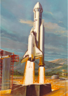
Artist's concept of 35-foot-diameter (10.6 m) Hammerhead configuration at launch.

During the lifetime of the Space Shuttle, Rockwell International and many other organizations studied various Space Shuttle designs. These involved different ways of increasing cargo and crew capacity, as well as investigating further reusability. A large focus of these designs were related to developing new shuttle boosters and improvements to the central tank, but also looked to expand NASA's ability to launch deep space missions and build modular space stations. Many of these concepts and studies would shape the concepts and programs of the 2000s such as the Constellation, Orbital Space Plane Program, and Artemis program.

Shuttle-derived vehicles
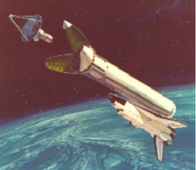
Artist's concept of 25-foot-diameter (7.6 m) fairing

Shuttle-C

The Heavy Lift Launch Vehicle was a study by NASA to turn the Space Shuttle launch stack into a dedicated uncrewed cargo launcher. The external tank and Space Shuttle Solid Rocket Boosters (SRBs) would be combined with a cargo module that took the place of the shuttle orbiter and included the Space Shuttle Main Engines. A ballistic return pod would be used as the main engine structure and carry 2-4 SSMEs as well as mount the payload/booster stage. It would be recovered via parachutes in the Australian outback or northern Mexico. Small lifting wings were added to allow more accurate landings. Various Heavy Lift Launch Vehicle concepts were investigated between 1984 and 1995 and it would eventually become known as the Shuttle-C, which lacked reusable engines and ballistic return pods.

The Shuttle-C concept would theoretically cut development costs for a heavy launch vehicle by re-using technology developed for the Shuttle program. End-of-life and Space Shuttle hardware would also have been used. One proposal involved converting the Columbia or Enterprise into a single-use cargo launcher.

With the Shuttle-C, it was thought that the lower maintenance and safety requirements for the uncrewed vehicle would allow a higher flight rate. Before the loss of Space Shuttle Challenger, NASA had expected about 14 shuttle flights a year. In the aftermath of the Challenger incident, it became clear that this launch rate was not feasible for a variety of reasons.

The Shuttle-C would also launch an uncrewed lunar lander and propulsion module while a second vehicle would launch the Crew Exploration Vehicle to perform lunar missions. The Shuttle-C would additionally act as the crewed component of the International Lunar Resources Exploration Concept proposed in 1993.


In the early 1990s, NASA engineers planning a crewed mission to Mars included a Shuttle-C design to launch six non reusable 80-ton segments to create two Mars ships in Earth orbit. After President George W. Bush called for the end of the Space Shuttle by 2010, these proposed configurations were put aside.

HLLV

Magnum

The Magnum was a large Super heavy-lift launch vehicle designed by NASA's Marshall Space Flight Center during the mid-1990s. The Magnum would have been a booster around 315 feet (96 m) tall, on the scale of the Saturn V, and was originally designed to carry a human mission to Mars. It was to have used two strap-on side boosters, similar to the Space Shuttle Solid Rocket Boosters (SRBs), but using liquid fuel instead. Some designs had strap-on boosters using wings and jet engines, which would enable them to fly back to the launch area after they were jettisoned in flight. The Magnum was designed to carry around 80 tons of payload into low Earth orbit (LEO).
National Launch System

National Launch System

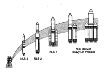
The National Launch System (or New Launch System) was a study authorized in 1991 by President George H. W. Bush to outline alternatives to the Space Shuttle for access to Earth orbit. Shortly thereafter, NASA asked Lockheed Missiles and Space, McDonnell Douglas, and TRW to perform a ten-month study.
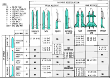
A Wide Variety of Booster, External Tank, and Propellant Options Were Studied

A series of launch vehicles was proposed, based on the proposed Space Transportation Main Engine (STME) liquid-fuel rocket engine. The STME was to be a simplified, expendable version of the RS-25 engine. The NLS-1 was the largest of the three proposed vehicles and would have used a modified Space Shuttle external tank for its core stage. The tank would have fed liquid oxygen and liquid hydrogen to four STMEs attached to the bottom of the tank. A payload or second stage would have fit atop the core stage, and two detachable Space Shuttle Solid Rocket Boosters would have been mounted on the sides of the core stage as on the Shuttle. Period illustrations suggest that much larger rockets than NLS-1 were contemplated, using multiples of the NLS-1 core stage.

Upgraded boosters

Early studies looked at alternate booster and external tank configurations such as:

  • SRM options that placed the SRBs inline but aft of the external tank (ET)
  • Liquid rocket boosters, both hydrogen and propane to replace the SRBs
  • Twin and catamaran flyback boosters to replace the SRBs
  • An engine pod aft of the ET fed from twin fuel tanks where the SRBs would normally be located
  • An in-line integrated booster/ET with a recoverable aft-engine pod
  • Tandem boosters and ETs in a variety of recoverable concepts
  • A single booster with multiple ETs (expendable and recoverable)

Advanced Solid Rocket Motor (ASRM) Project

NASA had planned on replacing the post-Challenger SRBs with a new Advanced Solid Rocket Motor (ASRM) to be built by Aerojet. They would have been built at a new facility designed by a subcontractor, RUST International, on the location of a canceled Tennessee Valley Authority nuclear power plant in Yellow Creek, Mississippi. The ASRM would have produced additional thrust in order to increase the shuttle payload to carry modules and construction components to the ISS. The ASRM program was canceled in 1993, after robotic assembly systems and computers were on-site and approximately 2 billion dollars spent, after NASA opted to instead issue minor corrections to the existing SRBs.
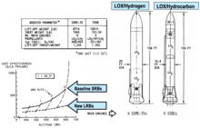
NASA/MSFC design for Recoverable Liquid Boosters

Recoverable Liquid Booster

A large focus of the NASA/MSFC Shuttle Growth Study contract was upgraded Recoverable Liquid Boosters. The boosters would have a similar flight path to the solid rocket motors, separating and deploying a parachute for recovery in the Atlantic Ocean. They were to be water-recoverable and used clamshell doors to protect the engines from saltwater immersion.

Liquid Fly-back Booster

Liquid Flyback Booster concepts date back to the early 1970s. Original Shuttle boosters were massive piloted fly-back boosters. The concept was studied throughout the 1980s but shelved after the Challenger disaster shut down most Shuttle upgrades. The Flyback booster concept reemerged in 1997 during the NASA Liquid Flyback Booster Study. The concept was abandoned due to the increased complexity and minor returns. The Shuttle Growth Study built on this background by developing design concepts in great detail for the liquid rocket boosters.
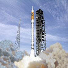
The Ares I launch vehicle would have used a Five-Segment SRB

Five-Segment Booster

Prior to the destruction of the Space Shuttle Columbia in 2003, NASA investigated the replacement of the current 4-segment SRBs with either a 5-segment SRB design or replacing them altogether with liquid "flyback" boosters using either Atlas V or Delta IV EELV technologies. The 5-segment SRB, which would have required little change to the current shuttle infrastructure, would have allowed the space shuttle to carry an additional 20,000 lb (9,100 kg) of payload in a 51.6°-inclination orbit, eliminate the dangerous "Return-to-Launch Site" (RTLS) and "Trans-Oceanic Abort" (TAL) modes, and, by using a so-called "dog-leg maneuver", fly south-to-north polar orbiting flights from Kennedy Space Center. After the destruction of Columbia, NASA shelved the five-segment SRB for the Shuttle Program, and the three surviving Orbiters, Discovery, Atlantis, and Endeavour were retired in 2011 after the completion of the International Space Station. One five-segment engineering test motor, ETM-03, was fired on October 23, 2003.

As part of the Constellation program, the first stage of the Ares I rocket was planned to use five-segment SRBs – in September 2009 a five-segment Space Shuttle SRB was static fired on the ground in ATK's desert testing area in Utah.

After the Constellation program was canceled in 2011, the new Space Launch System (SLS) was designated to use five-segment boosters. The first test of an SRB for SLS was completed in early 2015, and a second test was performed in mid-2016 at Orbital ATK's Promontory, Utah facility.

External Tank Cargo Fairing
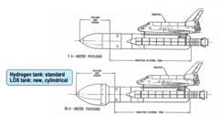
Space Shuttle 7.6 and 10.6 Fairing

DARPA studied modifying the current external tank design to be able to carry low-density payloads in a 25 or 35 ft (7.6 or 10.6 m) diameter fairing where the oxygen tank was currently. The Shuttle on average would only fly 66% of its payload capability but at nearly 100% of its payload volume. The external tank payload fairing would solve this problem. The oxygen tank would be redesigned as a cylindrical tank rather than conical and the clamshell payload fairing would be mounted directly on it. In this configuration, the orbiter would launch without any payload. These studies were eventually abandoned due to the fact that the new aerodynamic profile would make a Return to Launch Site (RTLS) maneuver impossible. The proposal was reconfigured as an Aft Cargo Carrier (ACC) to be positioned towards the bottom of the tank rather than on top. This idea made it far into development with Martin Marietta contracted to design and fabricate the container. The first flights of the ACC were expected in 1986. However, after the Challenger disaster, the ACC as well as most payload-related Shuttle upgrades were canceled.

Modified orbiters

The following are all accounts mentioned or discussed by Carl F. Ehrlich, Jr. in Shuttle Variations And Derivatives That Never Happened - An Historical Review

Stretched orbiter

In anticipation of upgraded boosters for the Shuttle, a design for a stretched orbiter was made. It would have had a larger payload bay with an additional 15 feet (4.6 m) in length giving it a payload capacity of 75 feet (23 m) and expected to carry payloads of up to 100,000 lb (45,000 kg). A new wing root and carry-through structure were designed to handle the additional weight at landing, keeping the outboard section of the original wings and requiring minimal modification. The 15-foot (4.6 m) barrel section would be attached just forward of the 1305 bulkhead towards the rear of the vehicle.

Humpback orbiter
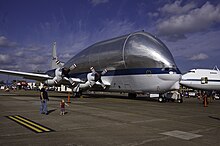
The Super Guppy's "humpback" design

An undefined need for more payload led to the idea of using the lee side section of the payload bay (at the entry angle of attack) as an expanded payload bay. This would result in a "humpback" outsize cargo vehicle similar to the Airbus Beluga or the Aero Spacelines Super Guppy. The hypersonic aerodynamic characteristics during re-entry would stay mostly the same however issues would have most likely occurred at subsonic speeds without a high angle of attack.

Unpowered orbiter

The Space Shuttle Enterprise unpowered test vehicle would have been the basis for the unpowered orbiter

As an internal response to the Soviets' engineless Buran orbiter, an unpowered Orbiter was designed at Marshall Space Flight Center. A payload bay segment would be added to the rear of the spacecraft and look very similar to the Space Shuttle Enterprise albeit with a few differences. Most of the equipment was stored in the rear of the craft to make up for lost weight and compensate for a lack of engines.
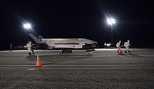
The Boeing X-37B, the only CRV and OSP design to make it into production

Crew Emergency Return Vehicle

From the late 1980s to the early 2000s NASA, in one form or another, pursued the Crew Return Vehicle; a small spaceplane/capsule capable of returning crew from a space station in the event of an emergency. Candidates evaluated included an Apollo-derived capsule, NASA's HL-20, HL-10, and M2F2, and the Air Force's X-24A. A sub-scale variant of the shuttle was proposed based on the ballistic return pod that was studied for the HLLV. The pressurized crew section would be modified into a lifting body. The main advantage of this design would be the proven technology and re-entry profile of the Shuttle.

High Capacity Orbiter

A conceptual design for a high-capacity orbiter was drawn up. The concept used a series of canisters mounted in the payload bay that would carry 68 to 74 passengers in a double-deck configuration similar to a Boeing 747. This moved the center of mass forward requiring minor changes to the wing structure adding more canard-like surfaces to allow more lifting surfaces. The design would be used for a Von Braun-style space station that would need crew capacity in the hundreds.

Non-ballistic atmospheric entry

From Wikipedia, the free encyclopedia
Phases of a skip reentry

Non-ballistic atmospheric entry is a class of atmospheric entry trajectories that follow a non-ballistic trajectory by employing aerodynamic lift in the high upper atmosphere. It includes trajectories such as skip and glide.

Skip is a flight trajectory where the spacecraft goes in and out the atmosphere. Glide is a flight trajectory where the spacecraft stays in the atmosphere for a sustained flight period of time. In most examples, a skip reentry roughly doubles the range of suborbital spaceplanes and reentry vehicles over the purely ballistic trajectory. In others, a series of skips allows the range to be further extended.

Non-ballistic atmospheric entry was first seriously studied as a way to extend the range of ballistic missiles, but was not used operationally in this form as conventional missiles with extended range were introduced. The underlying aerodynamic concepts have been used to produce maneuverable reentry vehicles (MARV), to increase the accuracy of some missiles like the Pershing II. More recently, the concepts have been used to produce hypersonic glide vehicles (HGV) to avoid interception as in the case of the Avangard. The range-extension is used as a way to allow flights at lower altitudes, helping avoid radar detection for a longer time compared to a higher ballistic path.

The concept has also been used to extend the reentry time for vehicles returning to Earth from the Moon, which would otherwise have to shed a large amount of velocity in a short time and thereby suffer very high heating rates. The Apollo Command Module used what is essentially a one-skip reentry (or partial skip), as did the Soviet Zond and Chinese Chang'e 5-T1. More complex multi-skip reentry is proposed for newer vehicles like the Orion spacecraft.

History

Early concepts

The conceptual basis was first noticed by German artillery officers, who found that their Peenemünder Pfeilgeschosse arrow shells traveled much further when fired from higher altitudes. This was not entirely unexpected due to geometry and thinner air, but when these factors were accounted for, they still could not explain the much greater ranges being seen. Investigations at Peenemünde led them to discover that the longer trajectories in the thinner high-altitude air resulted in the shell having an angle of attack that produced aerodynamic lift at supersonic speeds. At the time this was considered highly undesirable because it made the trajectory very difficult to calculate, but its possible application for extending range was not lost on the observers.

In June 1939, Kurt Patt of Klaus Riedel's design office at Peenemünde proposed wings for converting rocket speed and altitude into aerodynamic lift and range. He calculated that this would roughly double range of the A-4 rockets from 275 kilometres (171 mi) to about 550 kilometres (340 mi). Early development was considered under the A-9 name, although little work other than wind tunnel studies at the Zeppelin-Staaken company would be carried out during the next few years. Low-level research continued until 1942 when it was cancelled.

The earliest known proposal for the boost-glide concept for truly long-range use dates to the 1941 Silbervogel, a proposal by Eugen Sänger for a rocket powered bomber able to attack New York City from bases in Germany then fly on for landing somewhere in the Pacific Ocean held by the Empire of Japan. The idea would be to use the vehicle's wings to generate lift and pull up into a new ballistic trajectory, exiting the atmosphere again and giving the vehicle time to cool off between the skips. It was later demonstrated that the heating load during the skips was much higher than initially calculated, and would have melted the spacecraft.

In 1943, the A-9 work was dusted off again, this time under the name A-4b. It has been suggested this was either because it was now based on an otherwise unmodified A-4, or because the A-4 program had "national priority" by this time, and placing the development under the A-4 name guaranteed funding. A-4b used swept wings in order to extend the range of the V2 enough to allow attacks on UK cities in the Midlands or to reach London from areas deeper within Germany. The A-9 was originally similar, but later featured long ogival delta shaped wings instead of the more conventional swept ones. This design was adapted as a crewed upper stage for the A-9/A-10 intercontinental missile, which would glide from a point over the Atlantic with just enough range to bomb New York before the pilot bailed out.

Post-war development

To date, the X-20 Dyna Soar is the project that has come closest to actually building a crewed boost-glide vehicle. This illustration shows the Dyna Soar during reentry.

In the immediate post-war era, Soviet rocket engineer Aleksei Isaev found a copy of an updated August 1944 report on the Silbervogel concept. He had the paper translated to Russian, and it eventually came to the attention of Joseph Stalin who was intensely interested in the concept of an antipodal bomber. In 1946, he sent his son Vasily Stalin and scientist Grigori Tokaty, who had also worked on winged rockets before the war, to visit Sänger and Irene Bredt in Paris and attempt to convince them to join a new effort in the Soviet Union. Sänger and Bredt turned down the invitation.

In November 1946, the Soviets formed the NII-1 design bureau under Mstislav Keldysh to develop their own version without Sänger and Bredt. Their early work convinced them to convert from a rocket powered hypersonic skip-glide concept to a ramjet powered supersonic cruise missile, not unlike the Navaho being developed in the United States during the same period. Development continued for a time as the Keldysh bomber, but improvements in conventional ballistic missiles ultimately rendered the project unnecessary.

In the United States, the skip-glide concept was advocated by many of the German scientists who moved there, primarily Walter Dornberger and Krafft Ehricke at Bell Aircraft. In 1952, Bell proposed a bomber concept that was essentially a vertical launch version of Silbervogel known as Bomi. This led to a number of follow-on concepts during the 1950s, including Robo, Hywards, Brass Bell, and ultimately the Boeing X-20 Dyna-Soar. Earlier designs were generally bombers, while later models were aimed at reconnaissance or other roles. Dornberger and Ehricke also collaborated on a 1955 Popular Science article pitching the idea for airliner use.

The introduction of successful intercontinental ballistic missiles (ICBMs) in the offensive role ended any interest in the skip-glide bomber concepts, as did the reconnaissance satellite for the spyplane roles. The X-20 space fighter saw continued interest through the 1960s, but was ultimately the victim of budget cuts; after another review in March 1963, Robert McNamara canceled the program in December, noting that after $400 million had been spent they still had no mission for it to fulfill.

Missile use

Through the 1960s, the skip-glide concept saw interest not as a way to extend range, which was no longer a concern with modern missiles, but as the basis for maneuverable reentry vehicles for ICBMs. The primary goal was to have the RV change its path during reentry so that anti-ballistic missiles (ABMs) would not be able to track their movements rapidly enough for a successful interception. The first known example was the Alpha Draco tests of 1959, followed by the Boost Glide Reentry Vehicle (BGRV) test series, ASSET and PRIME.

This research was eventually put to use in the Pershing II's MARV reentry vehicle. In this case, there is no extended gliding phase; the warhead uses lift only for short periods to adjust its trajectory. This is used late in the reentry process, combining data from a Singer Kearfott inertial navigation system with a Goodyear Aerospace active radar. Similar concepts have been developed for most nuclear-armed nations' theatre ballistic missiles.

The Soviet Union had also invested some effort in the development of MARV to avoid US ABMs, but the closure of the US defenses in the 1970s meant there was no reason to continue this program. Things changed in the 2000s with the introduction of the US's Ground-Based Midcourse Defense, which led Russia to reanimate this work. The vehicle, referred to as Object 4202 in the Soviet era, was reported in October 2016 to have had a successful test. The system was revealed publicly on 1 March 2018 as the hypersonic glide vehicle (HGV) Avangard (Russian: Авангард; English: Vanguard), which officially entered active service as an ICBM payload on 27 December 2019. Vladimir Putin announced that Avangard had entered serial production, claiming that its maneuvrability makes it invulnerable to all current missile defences.

China has also developed a boost-glide warhead, the DF-ZF (known to US intelligence as "WU-14"). In contrast to the US and Russian MARV designs, the DF-ZF's primary goal is to use boost-glide to extend range while flying at lower altitudes than would be used to reach the same target using a purely ballistic path. This is intended to keep it out of the sight of the US Navy's Aegis Combat System radars as long as possible, and thereby decrease the time that system has to respond to an attack. DF-ZF was officially unveiled on 1 October 2019. Similar efforts by Russia led to the Kholod and GLL-8 Igla hypersonic test projects, and more recently the Yu-71 hypersonic glide vehicle which can be carried by RS-28 Sarmat.

Boost-glide became the topic of some interest as a possible solution to the US Prompt Global Strike (PGS) requirement, which seeks a weapon that can hit a target anywhere on the Earth within one hour of launch from the United States. PGS does not define the mode of operation, and current studies include Advanced Hypersonic Weapon boost-glide warhead, Falcon HTV-2 hypersonic aircraft, and submarine-launched missiles. Lockheed Martin is developing this concept as the hypersonic AGM-183A ARRW.

Reentry vehicle use

The technique was used by the Soviet Zond series of circumlunar spacecraft, which used one skip before landing. In this case a true skip was required in order to allow the spacecraft to reach the higher-latitude landing areas. Zond 6, Zond 7 and Zond 8 made successful skip entries, although Zond 5 did not. The Chang'e 5-T1, which flew mission profiles similar to Zond, also used this technique.

The Apollo Command Module used a skip-like concept to lower the heating loads on the vehicle by extending the re-entry time, but the spacecraft did not leave the atmosphere again and there has been considerable debate whether this makes it a true skip profile. NASA referred to it simply as "lifting entry". A true multi-skip profile was considered as part of the Apollo Skip Guidance concept, but this was not used on any crewed flights. The concept continues to appear on more modern vehicles like the Orion spacecraft, which made the first American skip entry in the Artemis 1 mission, using onboard computers.

Flight mechanics

Using simplified equations of motion and assuming that during the atmospheric flight both drag and lift forces will be much larger than the gravity force acting on the vehicle, the following analytical relations for a skip reentry flight can be derived:

where is the flightpath angle relative to the local horizontal, the subscript E indicates the conditions at the start of the entry and the subscript F indicates the conditions at the end of the entry flight.

The velocity before and after the entry can be derived to relate as follows:

Where is the lift-to-drag ratio of the vehicle.

Graphical user interface

From Wikipedia, the free encyclopedia

The graphical user interface, or GUI (/ˌjuːˈ/ JEE-yoo-EYE or /ˈɡi/ GOO-ee), is a form of user interface that allows users to interact with electronic devices through graphical icons and audio indicators such as primary notation, instead of text-based UIs, typed command labels or text navigation. GUIs were introduced in reaction to the perceived steep learning curve of command-line interfaces (CLIs), which require commands to be typed on a computer keyboard.

The actions in a GUI are usually performed through direct manipulation of the graphical elements.[ Beyond computers, GUIs are used in many handheld mobile devices such as MP3 players, portable media players, gaming devices, smartphones and smaller household, office and industrial controls. The term GUI tends not to be applied to other lower-display resolution types of interfaces, such as video games (where head-up displays (HUDs) are preferred), or not including flat screens like volumetric displays because the term is restricted to the scope of 2D display screens able to describe generic information, in the tradition of the computer science research at the Xerox Palo Alto Research Center.

GUI and interaction design

The GUI is presented (displayed) on the computer screen. It is the result of processed user input and usually the main interface for human-machine interaction. The touch UIs popular on small mobile devices are an overlay of the visual output to the visual input.

Designing the visual composition and temporal behavior of a GUI is an important part of software application programming in the area of human–computer interaction. Its goal is to enhance the efficiency and ease of use for the underlying logical design of a stored program, a design discipline named usability. Methods of user-centered design are used to ensure that the visual language introduced in the design is well-tailored to the tasks.

The visible graphical interface features of an application are sometimes referred to as chrome or GUI. Typically, users interact with information by manipulating visual widgets that allow for interactions appropriate to the kind of data they hold. The widgets of a well-designed interface are selected to support the actions necessary to achieve the goals of users. A model–view–controller allows flexible structures in which the interface is independent of and indirectly linked to application functions, so the GUI can be customized easily. This allows users to select or design a different skin at will, and eases the designer's work to change the interface as user needs evolve. Good GUI design relates to users more, and to system architecture less. Large widgets, such as windows, usually provide a frame or container for the main presentation content such as a web page, email message, or drawing. Smaller ones usually act as a user-input tool.

A GUI may be designed for the requirements of a vertical market as application-specific GUIs. Examples include automated teller machines (ATM), point of sale (POS) touchscreens at restaurants, self-service checkouts used in a retail store, airline self-ticket and check-in, information kiosks in a public space, like a train station or a museum, and monitors or control screens in an embedded industrial application which employ a real-time operating system (RTOS).

Cell phones and handheld game systems also employ application specific touchscreen GUIs. Newer automobiles use GUIs in their navigation systems and multimedia centers, or navigation multimedia center combinations.

Examples

Components

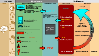
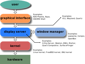
Layers of a GUI based on a windowing system

A GUI uses a combination of technologies and devices to provide a platform that users can interact with, for the tasks of gathering and producing information.

A series of elements conforming a visual language have evolved to represent information stored in computers. This makes it easier for people with few computer skills to work with and use computer software. The most common combination of such elements in GUIs is the windows, icons, text fields, canvases, menus, pointer (WIMP) paradigm, especially in personal computers.

The WIMP style of interaction uses a virtual input device to represent the position of a pointing device's interface, most often a mouse, and presents information organized in windows and represented with icons. Available commands are compiled together in menus, and actions are performed making gestures with the pointing device. A window manager facilitates the interactions between windows, applications, and the windowing system. The windowing system handles hardware devices such as pointing devices, graphics hardware, and positioning of the pointer.

In personal computers, all these elements are modeled through a desktop metaphor to produce a simulation called a desktop environment in which the display represents a desktop, on which documents and folders of documents can be placed. Window managers and other software combine to simulate the desktop environment with varying degrees of realism.

Entries may appear in a list to make space for text and details, or in a grid for compactness and larger icons with little space underneath for text. Variations inbetween exist, such as a list with multiple columns of items and a grid of items with rows of text extending sideways from the icon.

Multi-row and multi-column layouts commonly found on the web are "shelf" and "waterfall". The former is found on image search engines, where images appear with a fixed height but variable length, and is typically implemented with the CSS property and parameter display: inline-block;. A waterfall layout found on Imgur and Tweetdeck with fixed width but variable height per item is usually implemented by specifying column-width:.

Post-WIMP interface

Smaller app mobile devices such as personal digital assistants (PDAs) and smartphones typically use the WIMP elements with different unifying metaphors, due to constraints in space and available input devices. Applications for which WIMP is not well suited may use newer interaction techniques, collectively termed post-WIMP UIs.

As of 2011, some touchscreen-based operating systems such as Apple's iOS (iPhone) and Android use the class of GUIs named post-WIMP. These support styles of interaction using more than one finger in contact with a display, which allows actions such as pinching and rotating, which are unsupported by one pointer and mouse.

Interaction

Human interface devices, for the efficient interaction with a GUI include a computer keyboard, especially used together with keyboard shortcuts, pointing devices for the cursor (or rather pointer) control: mouse, pointing stick, touchpad, trackball, joystick, virtual keyboards, and head-up displays (translucent information devices at the eye level).

There are also actions performed by programs that affect the GUI. For example, there are components like inotify or D-Bus to facilitate communication between computer programs.

History

Early efforts

Ivan Sutherland developed Sketchpad in 1963, widely held as the first graphical computer-aided design program. It used a light pen to create and manipulate objects in engineering drawings in realtime with coordinated graphics. In the late 1960s, researchers at the Stanford Research Institute, led by Douglas Engelbart, developed the On-Line System (NLS), which used text-based hyperlinks manipulated with a then-new device: the mouse. (A 1968 demonstration of NLS became known as "The Mother of All Demos.") In the 1970s, Engelbart's ideas were further refined and extended to graphics by researchers at Xerox PARC and specifically Alan Kay, who went beyond text-based hyperlinks and used a GUI as the main interface for the Smalltalk programming language, which ran on the Xerox Alto computer, released in 1973. Most modern general-purpose GUIs are derived from this system.

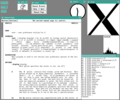
The Xerox PARC GUI consisted of graphical elements such as windows, menus, radio buttons, and check boxes. The concept of icons was later introduced by David Canfield Smith, who had written a thesis on the subject under the guidance of Kay. The PARC GUI employs a pointing device along with a keyboard. These aspects can be emphasized by using the alternative term and acronym for windows, icons, menus, pointing device (WIMP). This effort culminated in the 1973 Xerox Alto, the first computer with a GUI, though the system never reached commercial production.

The first commercially available computer with a GUI was 1979 PERQ workstation, manufactured by Three Rivers Computer Corporation. Its design was heavily influenced by the work at Xerox PARC. In 1981, Xerox eventually commercialized the Alto in the form of a new and enhanced system – the Xerox 8010 Information System – more commonly known as the Xerox Star. These early systems spurred many other GUI efforts, including Lisp machines by Symbolics and other manufacturers, the Apple Lisa (which presented the concept of menu bar and window controls) in 1983, the Apple Macintosh 128K in 1984, and the Atari ST with Digital Research's GEM, and Commodore Amiga in 1985. Visi On was released in 1983 for the IBM PC compatible computers, but was never popular due to its high hardware demands. Nevertheless, it was a crucial influence on the contemporary development of Microsoft Windows.

Apple, Digital Research, IBM and Microsoft used many of Xerox's ideas to develop products, and IBM's Common User Access specifications formed the basis of the GUIs used in Microsoft Windows, IBM OS/2 Presentation Manager, and the Unix Motif toolkit and window manager. These ideas evolved to create the interface found in current versions of Microsoft Windows, and in various desktop environments for Unix-like operating systems, such as macOS and Linux. Thus most current GUIs have largely common idioms.

An Apple Lisa (1983) demonstrating LisaOS, Apple Computer's first commercially available GUI.

Popularization

HP LX System Manager running on a HP 200LX.

GUIs were a hot topic in the early 1980s. The Apple Lisa was released in 1983, and various windowing systems existed for DOS operating systems (including PC GEM and PC/GEOS). Individual applications for many platforms presented their own GUI variants. Despite the GUIs advantages, many reviewers questioned the value of the entire concept, citing hardware limits, and problems in finding compatible software.

In 1984, Apple released a television commercial which introduced the Apple Macintosh during the telecast of Super Bowl XVIII by CBS, with allusions to George Orwell's noted novel Nineteen Eighty-Four. The goal of the commercial was to make people think about computers, identifying the user-friendly interface as a personal computer which departed from prior business-oriented systems, and becoming a signature representation of Apple products.

Windows 95, accompanied by an extensive marketing campaign, was a major success in the marketplace at launch and shortly became the most popular desktop operating system.

In 2007, with the iPhone and later in 2010 with the introduction of the iPad, Apple popularized the post-WIMP style of interaction for multi-touch screens, and those devices were considered to be milestones in the development of mobile devices.

The GUIs familiar to most people as of the mid-late 2010s are Microsoft Windows, macOS, and the X Window System interfaces for desktop and laptop computers, and Android, Apple's iOS, Symbian, BlackBerry OS, Windows Phone/Windows 10 Mobile, Tizen, WebOS, and Firefox OS for handheld (smartphone) devices.

Comparison to other interfaces

Command-line interfaces

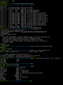
A modern CLI

Since the commands available in command line interfaces can be many, complex operations can be performed using a short sequence of words and symbols. Custom functions may be used to facilitate access to frequent actions. Command-line interfaces are more lightweight, as they only recall information necessary for a task; for example, no preview thumbnails or graphical rendering of web pages. This allows greater efficiency and productivity once many commands are learned. But reaching this level takes some time because the command words may not be easily discoverable or mnemonic. Also, using the command line can become slow and error-prone when users must enter long commands comprising many parameters or several different filenames at once. However, windows, icons, menus, pointer (WIMP) interfaces present users with many widgets that represent and can trigger some of the system's available commands.

GUIs can be made quite hard when dialogs are buried deep in a system or moved about to different places during redesigns. Also, icons and dialog boxes are usually harder for users to script.

WIMPs extensively use modes, as the meaning of all keys and clicks on specific positions on the screen are redefined all the time. Command-line interfaces use modes only in limited forms, such as for current directory and environment variables.

Most modern operating systems provide both a GUI and some level of a CLI, although the GUIs usually receive more attention.

GUI wrappers

GUI wrappers find a way around the command-line interface versions (CLI) of (typically) Linux and Unix-like software applications and their text-based UIs or typed command labels. While command-line or text-based applications allow users to run a program non-interactively, GUI wrappers atop them avoid the steep learning curve of the command-line, which requires commands to be typed on the keyboard. By starting a GUI wrapper, users can intuitively interact with, start, stop, and change its working parameters, through graphical icons and visual indicators of a desktop environment, for example. Applications may also provide both interfaces, and when they do the GUI is usually a WIMP wrapper around the command-line version. This is especially common with applications designed for Unix-like operating systems. The latter used to be implemented first because it allowed the developers to focus exclusively on their product's functionality without bothering about interface details such as designing icons and placing buttons. Designing programs this way also allows users to run the program in a shell script.

Three-dimensional graphical user interface

Many environments and games use the methods of 3D graphics to project 3D GUI objects onto the screen. The use of 3D graphics has become increasingly common in mainstream operating systems (ex. Windows Aero, and Aqua (MacOS)) to create attractive interfaces, termed eye candy (which includes, for example, the use of drop shadows underneath windows and the cursor), or for functional purposes only possible using three dimensions. For example, user switching is represented by rotating a cube with faces representing each user's workspace, and window management is represented via a Rolodex-style flipping mechanism in Windows Vista (see Windows Flip 3D). In both cases, the operating system transforms windows on-the-fly while continuing to update the content of those windows.

The GUI is usually WIMP-based, although occasionally other metaphors surface, such as those used in Microsoft Bob, 3dwm, File System Navigator, File System Visualizer, 3D Mailbox, and GopherVR. Zooming (ZUI) is a related technology that promises to deliver the representation benefits of 3D environments without their usability drawbacks of orientation problems and hidden objects. In 2006, Hillcrest Labs introduced the first ZUI for television. Other innovations include the menus on the PlayStation 2, the menus on the Xbox, Sun's Project Looking Glass, Metisse, which was similar to Project Looking Glass, BumpTop, where users can manipulate documents and windows with realistic movement and physics as if they were physical documents, Croquet OS, which is built for collaboration, and compositing window managers such as Enlightenment and Compiz. Augmented reality and virtual reality also make use of 3D GUI elements.

In science fiction

3D GUIs have appeared in science fiction literature and films, even before certain technologies were feasible or in common use.

Entropy (information theory)

From Wikipedia, the free encyclopedia https://en.wikipedia.org/wiki/Entropy_(information_theory) In info...