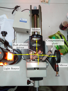

The Michelson interferometer is a common configuration for optical interferometry and was invented by the 19/20th-century American physicist Albert Abraham Michelson. Using a beam splitter, a light source is split into two arms. Each of those light beams is reflected back toward the beamsplitter which then combines their amplitudes using the superposition principle. The resulting interference pattern that is not directed back toward the source is typically directed to some type of photoelectric detector or camera. For different applications of the interferometer, the two light paths can be with different lengths or incorporate optical elements or even materials under test.
The Michelson interferometer (among other interferometer configurations) is employed in many scientific experiments and became well known for its use by Michelson and Edward Morley in the famous Michelson–Morley experiment (1887) in a configuration which would have detected the Earth's motion through the supposed luminiferous aether that most physicists at the time believed was the medium in which light waves propagated. The null result of that experiment essentially disproved the existence of such an aether, leading eventually to the special theory of relativity and the revolution in physics at the beginning of the twentieth century. In 2015, another application of the Michelson interferometer, LIGO, made the first direct observation of gravitational waves. That observation confirmed an important prediction of general relativity, validating the theory's prediction of space-time distortion in the context of large scale cosmic events (known as strong field tests).
Configuration

A Michelson interferometer consists minimally of mirrors M1 & M2 and a beam splitter M. In Fig 2, a source S emits light that hits the beam splitter (in this case, a plate beamsplitter) surface M at point C. M is partially reflective, so part of the light is transmitted through to point B while some is reflected in the direction of A. Both beams recombine at point C' to produce an interference pattern incident on the detector at point E (or on the retina of a person's eye). If there is a slight angle between the two returning beams, for instance, then an imaging detector will record a sinusoidal fringe pattern as shown in Fig. 3b. If there is perfect spatial alignment between the returning beams, then there will not be any such pattern but rather a constant intensity over the beam dependent on the differential pathlength; this is difficult, requiring very precise control of the beam paths.
Fig. 2 shows use of a coherent (laser) source. Narrowband spectral light from a discharge or even white light can also be used, however to obtain significant interference contrast it is required that the differential pathlength is reduced below the coherence length of the light source. That can be only micrometers for white light, as discussed below.
If a lossless beamsplitter is employed, then one can show that optical energy is conserved. At every point on the interference pattern, the power that is not directed to the detector at E is rather present in a beam (not shown) returning in the direction of the source.


As shown in Fig. 3a and 3b, the observer has a direct view of mirror M1 seen through the beam splitter, and sees a reflected image M'2 of mirror M2. The fringes can be interpreted as the result of interference between light coming from the two virtual images S'1 and S'2 of the original source S. The characteristics of the interference pattern depend on the nature of the light source and the precise orientation of the mirrors and beam splitter. In Fig. 3a, the optical elements are oriented so that S'1 and S'2 are in line with the observer, and the resulting interference pattern consists of circles centered on the normal to M1 and M'2 (fringes of equal inclination). If, as in Fig. 3b, M1 and M'2 are tilted with respect to each other, the interference fringes will generally take the shape of conic sections (hyperbolas), but if M1 and M'2 overlap, the fringes near the axis will be straight, parallel, and equally spaced (fringes of equal thickness). If S is an extended source rather than a point source as illustrated, the fringes of Fig. 3a must be observed with a telescope set at infinity, while the fringes of Fig. 3b will be localized on the mirrors.
Source bandwidth

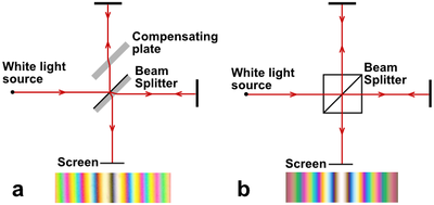
White light has a tiny coherence length and is difficult to use in a Michelson (or Mach–Zehnder) interferometer. Even a narrowband (or "quasi-monochromatic") spectral source requires careful attention to issues of chromatic dispersion when used to illuminate an interferometer. The two optical paths must be practically equal for all wavelengths present in the source. This requirement can be met if both light paths cross an equal thickness of glass of the same dispersion. In Fig. 4a, the horizontal beam crosses the beam splitter three times, while the vertical beam crosses the beam splitter once. To equalize the dispersion, a so-called compensating plate identical to the substrate of the beam splitter may be inserted into the path of the vertical beam. In Fig. 4b, we see using a cube beam splitter already equalizes the pathlengths in glass. The requirement for dispersion equalization is eliminated by using extremely narrowband light from a laser.
The extent of the fringes depends on the coherence length of the source. In Fig. 3b, the yellow sodium light used for the fringe illustration consists of a pair of closely spaced lines, D1 and D2, implying that the interference pattern will blur after several hundred fringes. Single longitudinal mode lasers are highly coherent and can produce high contrast interference with differential pathlengths of millions or even billions of wavelengths. On the other hand, using white (broadband) light, the central fringe is sharp, but away from the central fringe the fringes are colored and rapidly become indistinct to the eye.
Early experimentalists attempting to detect the earth's velocity relative to the supposed luminiferous aether, such as Michelson and Morley (1887) and Miller (1933), used quasi-monochromatic light only for initial alignment and coarse path equalization of the interferometer. Thereafter they switched to white (broadband) light, since using white light interferometry they could measure the point of absolute phase equalization (rather than phase modulo 2π), thus setting the two arms' pathlengths equal. More importantly, in a white light interferometer, any subsequent "fringe jump" (differential pathlength shift of one wavelength) would always be detected.
Applications

The Michelson interferometer configuration is used in a number of different applications.
Fourier transform spectrometer
Fig. 5 illustrates the operation of a Fourier transform spectrometer, which is essentially a Michelson interferometer with one mirror movable. (A practical Fourier transform spectrometer would substitute corner cube reflectors for the flat mirrors of the conventional Michelson interferometer, but for simplicity, the illustration does not show this.) An interferogram is generated by making measurements of the signal at many discrete positions of the moving mirror. A Fourier transform converts the interferogram into an actual spectrum. Fourier transform spectrometers can offer significant advantages over dispersive (i.e., grating and prism) spectrometers under certain conditions. (1) The Michelson interferometer's detector in effect monitors all wavelengths simultaneously throughout the entire measurement. When using a noisy detector, such as at infrared wavelengths, this offers an increase in signal-to-noise ratio while using only a single detector element; (2) the interferometer does not require a limited aperture as do grating or prism spectrometers, which require the incoming light to pass through a narrow slit in order to achieve high spectral resolution. This is an advantage when the incoming light is not of a single spatial mode. For more information, see Fellgett's advantage.
Twyman–Green interferometer

The Twyman–Green interferometer is a variation of the Michelson interferometer used to test small optical components, invented and patented by Twyman and Green in 1916. The basic characteristics distinguishing it from the Michelson configuration are the use of a monochromatic point light source and a collimator. Michelson (1918) criticized the Twyman–Green configuration as being unsuitable for the testing of large optical components, since the available light sources had limited coherence length. Michelson pointed out that constraints on geometry forced by the limited coherence length required the use of a reference mirror of equal size to the test mirror, making the Twyman–Green impractical for many purposes. Decades later, the advent of laser light sources answered Michelson's objections.
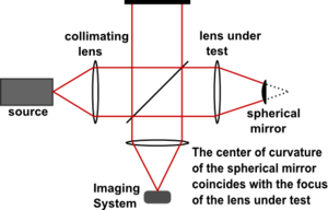
The use of a figured reference mirror in one arm allows the Twyman–Green interferometer to be used for testing various forms of optical component, such as lenses or telescope mirrors. Fig. 6 illustrates a Twyman–Green interferometer set up to test a lens. A point source of monochromatic light is expanded by a diverging lens (not shown), then is collimated into a parallel beam. A convex spherical mirror is positioned so that its center of curvature coincides with the focus of the lens being tested. The emergent beam is recorded by an imaging system for analysis.
Laser unequal path interferometer
The "LUPI" is a Twyman–Green interferometer that uses a coherent laser light source. The high coherence length of a laser allows unequal path lengths in the test and reference arms and permits economical use of the Twyman–Green configuration in testing large optical components. A similar scheme has been used by Tajammal M in his PhD thesis (Manchester University UK, 1995) to balance two arms of an LDA system. This system used fibre optic direction coupler.
Stellar measurements
The Michelson stellar interferometer is used for measuring the diameter of stars. In 1920, Michelson and Francis G. Pease used it to measure the diameter of Betelgeuse, the first time the diameter of a star other than the sun was measured.
Gravitational wave detection
Michelson interferometry is the leading method for the direct detection of gravitational waves. This involves detecting tiny strains in space itself, affecting two long arms of the interferometer unequally, due to a strong passing gravitational wave. In 2015 the first detection of gravitational waves was accomplished using the two Michelson interferometers, each with 4 km arms, which comprise the Laser Interferometer Gravitational-Wave Observatory. This was the first experimental validation of gravitational waves, predicted by Albert Einstein's General Theory of Relativity. With the addition of the Virgo interferometer in Europe, it became possible to calculate the direction from which the gravitational waves originate, using the tiny arrival-time differences between the three detectors. In 2020, India was constructing a fourth Michelson interferometer for gravitational wave detection.
Miscellaneous applications

Fig. 7 illustrates use of a Michelson interferometer as a tunable narrow band filter to create dopplergrams of the Sun's surface. When used as a tunable narrow band filter, Michelson interferometers exhibit a number of advantages and disadvantages when compared with competing technologies such as Fabry–Pérot interferometers or Lyot filters. Michelson interferometers have the largest field of view for a specified wavelength, and are relatively simple in operation, since tuning is via mechanical rotation of waveplates rather than via high voltage control of piezoelectric crystals or lithium niobate optical modulators as used in a Fabry–Pérot system. Compared with Lyot filters, which use birefringent elements, Michelson interferometers have a relatively low temperature sensitivity. On the negative side, Michelson interferometers have a relatively restricted wavelength range, and require use of prefilters which restrict transmittance. The reliability of Michelson interferometers has tended to favor their use in space applications, while the broad wavelength range and overall simplicity of Fabry–Pérot interferometers has favored their use in ground-based systems.

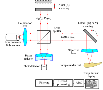
Another application of the Michelson interferometer is in optical coherence tomography (OCT), a medical imaging technique using low-coherence interferometry to provide tomographic visualization of internal tissue microstructures. As seen in Fig. 8, the core of a typical OCT system is a Michelson interferometer. One interferometer arm is focused onto the tissue sample and scans the sample in an X-Y longitudinal raster pattern. The other interferometer arm is bounced off a reference mirror. Reflected light from the tissue sample is combined with reflected light from the reference. Because of the low coherence of the light source, interferometric signal is observed only over a limited depth of sample. X-Y scanning therefore records one thin optical slice of the sample at a time. By performing multiple scans, moving the reference mirror between each scan, an entire three-dimensional image of the tissue can be reconstructed. Recent advances have striven to combine the nanometer phase retrieval of coherent interferometry with the ranging capability of low-coherence interferometry.
Others applications include delay line interferometer which convert phase modulation into amplitude modulation in DWDM networks, the characterization of high-frequency circuits, and low-cost THz power generation.
Atmospheric and space applications
The Michelson Interferometer has played an important role in studies of the upper atmosphere, revealing temperatures and winds, employing both space-borne, and ground-based instruments, by measuring the Doppler widths and shifts in the spectra of airglow and aurora. For example, the Wind Imaging Interferometer, WINDII, on the Upper Atmosphere Research Satellite, UARS, (launched on September 12, 1991) measured the global wind and temperature patterns from 80 to 300 km by using the visible airglow emission from these altitudes as a target and employing optical Doppler interferometry to measure the small wavelength shifts of the narrow atomic and molecular airglow emission lines induced by the bulk velocity of the atmosphere carrying the emitting species. The instrument was an all-glass field-widened achromatically and thermally compensated phase-stepping Michelson interferometer, along with a bare CCD detector that imaged the airglow limb through the interferometer. A sequence of phase-stepped images was processed to derive the wind velocity for two orthogonal view directions, yielding the horizontal wind vector.
The principle of using a polarizing Michelson Interferometer as a narrow band filter was first described by Evans who developed a birefringent photometer where the incoming light is split into two orthogonally polarized components by a polarizing beam splitter, sandwiched between two halves of a Michelson cube. This led to the first polarizing wide-field Michelson interferometer described by Title and Ramsey which was used for solar observations; and led to the development of a refined instrument applied to measurements of oscillations in the sun's atmosphere, employing a network of observatories around the Earth known as the Global Oscillations Network Group (GONG).

The Polarizing Atmospheric Michelson Interferometer, PAMI, developed by Bird et al., and discussed in Spectral Imaging of the Atmosphere, combines the polarization tuning technique of Title and Ramsey with the Shepherd et al. technique of deriving winds and temperatures from emission rate measurements at sequential path differences, but the scanning system used by PAMI is much simpler than the moving mirror systems in that it has no internal moving parts, instead scanning with a polarizer external to the interferometer. The PAMI was demonstrated in an observation campaign where its performance was compared to a Fabry–Pérot spectrometer, and employed to measure E-region winds.
More recently, the Helioseismic and Magnetic Imager (HMI), on the Solar Dynamics Observatory, employs two Michelson Interferometers with a polarizer and other tunable elements, to study solar variability and to characterize the Sun's interior along with the various components of magnetic activity. HMI takes high-resolution measurements of the longitudinal and vector magnetic field over the entire visible disk thus extending the capabilities of its predecessor, the SOHO's MDI instrument (See Fig. 9). HMI produces data to determine the interior sources and mechanisms of solar variability and how the physical processes inside the Sun are related to surface magnetic field and activity. It also produces data to enable estimates of the coronal magnetic field for studies of variability in the extended solar atmosphere. HMI observations will help establish the relationships between the internal dynamics and magnetic activity in order to understand solar variability and its effects.
In one example of the use of the MDI, Stanford scientists reported the detection of several sunspot regions in the deep interior of the Sun, 1–2 days before they appeared on the solar disc. The detection of sunspots in the solar interior may thus provide valuable warnings about upcoming surface magnetic activity which could be used to improve and extend the predictions of space weather forecasts.
Technical topics
Step-phase interferometer
This is a Michelson interferometer in which the mirror in one arm is replaced with a Gires–Tournois etalon. The highly dispersed wave reflected by the Gires–Tournois etalon interferes with the original wave as reflected by the other mirror. Because the phase change from the Gires–Tournois etalon is an almost step-like function of wavelength, the resulting interferometer has special characteristics. It has an application in fiber-optic communications as an optical interleaver.
Both mirrors in a Michelson interferometer can be replaced with Gires–Tournois etalons. The step-like relation of phase to wavelength is thereby more pronounced, and this can be used to construct an asymmetric optical interleaver.
Phase-conjugating interferometry
The reflection from phase-conjugating mirror of two light beams inverses their phase difference to the opposite one . For this reason the interference pattern in twin-beam interferometer changes drastically. Compared to conventional Michelson interference curve with period of half-wavelength :
,
where is second-order correlation function, the interference curve in phase-conjugating interferometer has much longer period defined by frequency shift of reflected beams:
, where visibility curve is nonzero when optical path difference exceeds coherence length of light beams. The nontrivial features of phase fluctuations in optical phase-conjugating mirror had been studied via Michelson interferometer with two independent PC-mirrors . The phase-conjugating Michelson interferometry is a promising technology for coherent summation of laser amplifiers . Constructive interference in an array containing beamsplitters of laser beams synchronized by phase conjugation may increase the brightness of amplified beams as .


![{\displaystyle I(\Delta L)\sim [1+\gamma (\Delta L)\cos(2k\Delta L)]}](https://wikimedia.org/api/rest_v1/media/math/render/svg/cccdfd2322867179c4f04092d9ce3c4379383f7a)


![{\displaystyle I(\Delta L)\sim [1+[\gamma (\Delta L)+0.25]\cos(\Delta k\Delta L)]}](https://wikimedia.org/api/rest_v1/media/math/render/svg/b5cb51b7c5eb788de0df9bc91130b2e1d0deaad6)


